Technical Field:
The present invention relates to amechanismof detecting
the presence of staples, which are accommodated in a staple
cartridge, in an electric stapler.
Background Art:
In general, the following electric stapler is well
known. Sheet staples composed of a large number of linear
staples, which are connected with each other being formed into
a sheet-shape, are accommodated in a staple cartridge. This
staple cartridge is mounted in a passage, which is formed in
a magazine portion of the stapler body, used for attaching
the cartridge. After the staple cartridge has been inserted
and mounted, a staple at the lead of the sheet staples is stricken
out while both sides of the staple are being bent, and the
following staples are successively stricken out while both
sides of the staples are being bent. In this type electric
stapler, when a quantity of residual sheet staples in the staple
cartridge are decreased, it is necessary to pick up the cartridge
from the magazine portion and replace it with a new cartridge.
Therefore, it is necessary to provide a staple detecting sensor
for detecting the quantity of residual sheet staples in the
staple cartridge.
However, a space of the passage provided in the stapler
body, to which the staple cartridge is attached, is small.
Therefore, even when a common microswitch is attached into
the space, a stroke of the switch is too short. Accordingly,
the microswitch is operated even when the staple cartridge
is moved a little. For example, even when a sufficiently large
quantity of staples are left in the cartridge, when the sheet
staples are deformed being badly warped, the actuator of the
microswitch comes into action. Therefore, the reliability
of detection is unavoidably deteriorated. In the case where
the microswitch is arranged in the passage, when the actuator
is arranged making a right angle with the passage, it obstructs
the attaching and detaching work of the staple cartridge.
Accordingly, it is necessary to provide a mechanism to prevent
the actuator from protruding into the passage in the case of
inserting the staple cartridge, which increases the difficulties
of arranging the microswitch in the staple cartridge attaching
passage. Further, when the sensor is arranged at a position
close to the introducing port of the staple cartridge, at the
time of inserting the staple cartridge, the staple cartridge
is inclined with respect to the passage. Therefore, when the
cartridge is attached or detached, the staple cartridge is
hooked at the actuator, which causes damage to both the staple
cartridge and the actuator. In order to solve this problem,
it is necessary to provide a bigmargin of relief of the actuator.
As described above, it is very difficult to arrange
the common microswitch in the stapler body having only a small
space.
Summary of the invention:
The present invention has been accomplished to solve
the above problems. It is an object of the present invention
to provide a mechanism of detecting staples in an electric
stapler by which a quantity of residual staples can be positively
detected even when a space, in which the mechanism is arranged,
is small, when a profile and mode of operation of the actuator
are improved.
In order to solve the above problems, the present
invention provides a mechanism of detecting staples in an
electric stapler. The electric stapler is composed as follows.
A passage for attaching a staple cartridge is formed in a
magazine portion of the stapler body. In the staple cartridge,
sheet staples, in which a large number of linear staples are
connected to each other being formed into a sheet-shape, are
accommodated. Both sides of the lead staple and the following
staples of the sheet staples are successively bent and stricken
out by the electric stapler. In this electric stapler, the
mechanism of detecting staples is composed as follows. A staple
detection sensor, both side portions of the end of the actuator
of which are tapered, is arranged so that both the side portions
can be directed to an entrance of the passage and the end of
the actuator can be engaged with an upper or a lower face of
the sheet staples of the staple cartridge attached into the
passage. The actuator is attached so that the actuator can
be swung and tilted in the perpendicular direction to the
longitudinal direction of the passage, and the actuator is
biased by a spring so that it can be raised obliquely at all
times.
Brief description of the drawings:
Fig. 1 is a perspective view of the stapler body of the
electric stapler.
Fig. 2 is a simplified view of the side of the stapler
body of the electric stapler.
Fig. 3 is a rear view of the stapler body of the electric
stapler.
Fig. 4 is a perspective view of the staple cartridge,
wherein the view is taken from an upper face.
Fig. 5 is a perspective view of the staple cartridge,
wherein the view is taken from a lower face.
Fig. 6 is a partial perspective view of the sheet staples.
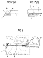
Fig. 7 (a) and Fig. 7(b) are a schematic illustration showing
a state in which the staple cartridge collides with the detection
sensor, wherein the illustration is taken from the side, and
a schematic illustration showing a state in which the staple
cartridge is attached, wherein the illustration is taken from
the rear side.
Fig. 8 is a side view showing an outline of the state
in which the staple cartridge is attached to the stapler body.
Fig. 9 is a rear view showing an outline of the state
in which the staple cartridge is attached to the stapler body.
Note that in the drawings, reference numeral 1 is a stapler
body, reference numeral 3 is a staple cartridge, reference
numeral 4 is a passage and reference numeral 8 is an actuator.
Description of the preferred embodiments:
Fig. 1 is a perspective view of the stapler body of the
electric stapler, Fig. 2 is a simplified view of the side of
the stapler body of the electric stapler and Fig. 3 is a rear
view of the stapler body of the electric stapler.
In the above electric stapler, the staple cartridge 3
shown in Figs. 4 and 5 is detachably attached to the magazine
portion 2 of the stapler body 1. In the staple cartridge 3,
a plurality of stages of sheet staples "a" (shown in Fig. 6),
in which a large number of linear staples are connected with
each other being formed into a sheet-shape as shown in Fig.
6, are stacked and accommodated. In the magazine portion 2
of the stapler body 1, the passage 4 for attaching the cartridge
is formed. The above staple cartridge 3 is inserted and attached
into the above passage 4. After the staple cartridge 3 has
been attached, the driver plate 5 provided in the stapler body
1 is driven upward, and a staple at the lead of the sheet staples
"a" is made to penetrate sheets of paper to be stapled. Further,
the upper arm 12 is driven downward so that both sides of the
staple, which has penetrated the sheets of paper to be stapled,
are bent. After the completion of biding the sheets of paper,
the driver plate 5 and the arm 12 are respectively descended
and ascended to the initial position, and the sheet staples
are fed forward by a feeding means (not shown) so as to prepare
for the next binding operation. The aforementioned operation
is repeated, and both sides of the staples are successively
bent and stricken out. In this connection, the mechanism of
bending both sides of the lead staple and striking the staple
is well known. Therefore, the explanations are omitted here.
Next, the sensor 7 for detecting the staple is arranged
in the neighborhood on the cartridge introducing portion side
of the passage 4 of the above magazine portion 2.
In this sensor 7, the switch is turned on and off when
the. actuator 8 provided in the switch body 7a is operated.
Both sides 8a, 8b of the end portion of the actuator 8 are
tapered. In this way, the actuator 8 is formed into a
triangular-plate-shape or trapezoidal-plate-shape. The
actuator 8 is attached so that it can be tilted with respect
to the switch body 7a. The tilting direction is perpendicular
to the face of the actuator 8. When the actuator 8 rises,
it is a little inclined with respect to the perpendicular
direction. The actuator 8 is biased by a spring not shown
so that it can rise at all times.
Next, the detection sensor 7 is arranged in the
neighborhood of the cartridge 3 introducing portion side (the
entrance side) of the passage 4. At this time, the staple
detection sensor 7 is attached so that both sides 8a, 8b described
above can be directed to the entrance of the passage 4. At
this time, the actuator 8 protrudes into the passage 4.
As shown in Figs. 4 and 5, the guide passage 10 of the
sheet staples "a" and the knob 11 are provided in the staple
cartridge 3. On the lower face of the guide passage 10, the
opening 9 is formed at the rear portion corresponding to the
detection sensor 7 when the staple cartridge 3 is inserted
into the magazine portion 2 of the stapler body 1, that is,
at the position on the knob side. The lower face of the sheet
staples "a", which are provided inside, is exposed from this
opening 9.
When the cartridge 3 is inserted into the passage 4 of
the stapler body 1, since the actuator 8 of the staple detection
sensor 7 protrudes into the passage 4, as shown in Fig. 7(a),
the forward end portion of the staple cartridge 3 comes into
contact with the inclined side portion 8a on the rear side
of the actuator 8 so that the actuator 8 can be pushed by the
forward end portion of the staple cartridge 3. Since the actuator
8 rises obliquely, when the inclined side portion 8a is pushed,
the actuator 8 is swung and tilted in the perpendicular direction
with respect to the longitudinal direction of the passage 4
as shown in Fig. 7(b). Fig. 8 is a side view showing a state
in which the staple cartridge 3 is attached, and Fig. 9 is
a rear view showing a state in which the staple cartridge 3
is attached. When the staple cartridge 3 is attached at a
predetermined position, the actuator 8 proceeds into the
cartridge 3 from the opening 9, which is formed in the lower
portion of the staple cartridge 3, by a force of the spring.
However, the actuator 8 is engaged with the lower face of
the sheet staples "a", which are accommodated in the cartridge
3, and tilted as shown in Fig. 7(b). This tilting state of
the actuator 8 is maintained.
After the staple cartridge 3 has been attached, when
the driver plate 5 provided in the stapler body 1 is driven
upward and downward, the staple "a1" at the lead of the sheet
staples "a" is successively stricken out while both sides of
the staple are being bent. Then, the staples "a" in the staple
cartridge 3 are consumed little by little. When a quantity
of the residual staples "a" are reduced and the trailing end
of the last sheet staple "a" passes through the staple detection
sensor 7, the actuator 8 is released. Therefore, as shown
by the dotted line in Fig. 7(b), the actuator 8 is swung by
the spring force and rises obliquely. Due to the above operation,
it can be detected that the staples "a1" have been used up.
Therefore, the staple cartridge 3 may be pulled out in the
opposite direction to the inserting direction and replaced
with a new staple cartridge 3. In the case of pulling out
the staple cartridge 3, the edge 9a (shown in Fig. 5) of the
opening 9 of the staple cartridge 3 comes into contact with
and pushes the inclined side portion 8b of the front side of
the actuator 8. Since the actuator 8 obliquely rises, when
the inclined side portion 8b is pushed, the actuator 8 is swung
and tilted resisting the spring force. Therefore, the actuator
8 does not obstruct the insertion of the staple cartridge 3.
Accordingly, the staple cartridge 3 can be smoothly and
positively attached to and detached from the stapler.
In this connection, in the above example, a.plurality
of stages of sheet staples are stacked in the staple cartridge
3 and the thus stacked sheet staples are successively consumed
from the upper stage. However, according to another example,
the stacked sheet staples are successively consumed from the.
lower stage. Further, according to still another example,
long sheet staples are spirally accommodated in the staple
cartridge. In this case, the staple detection sensor may be
arranged on the upper side of the passage, and the actuator
may be composed so that it can protrude from top to bottom.
In this connection, it should be noted that the present
invention is not limited to the above specific embodiment,
and variations may be made without departing from the scope
and spirit of the present invention. Of course, the variations
are included in the present invention.
This application is based on the Japanese Patent
Application (Patent Application No. 2001-253528) applied on
August 23, 2001. The contents of these applications are taken
in here as a reference.
Industrial Applicability:
As described above, the actuator 8 of the above detection
sensor is not protruded to and retracted from the passage 4
under the condition that it rises perpendicularly, but the
detection sensor is tilted with respect to the passage 4.
Therefore, the operation stroke of the actuator 8 is extended.
Accordingly, even when a space of the passage 4 is small,
no malfunction of the actuator 8 is caused, and the presence
of staples can be positively detected. Therefore, the
reliability of detection is high.
Since the actuator is composed in such a manner that
both side portions 8a, 8b of the end portion of the actuator
are tapered and the actuator can be freely tilted, and when
the actuator collides with the staple cartridge 3, it can move
so as to escape from the staple cartridge 3. Therefore, the
actuator 3 does not obstruct the attaching work of the staple
cartridge 3. Accordingly, a big relief margin of the actuator
8 is not required.