EP1428031B1 - Method handler for microfluidic instruments - Google Patents
Method handler for microfluidic instruments Download PDFInfo
- Publication number
- EP1428031B1 EP1428031B1 EP02765748A EP02765748A EP1428031B1 EP 1428031 B1 EP1428031 B1 EP 1428031B1 EP 02765748 A EP02765748 A EP 02765748A EP 02765748 A EP02765748 A EP 02765748A EP 1428031 B1 EP1428031 B1 EP 1428031B1
- Authority
- EP
- European Patent Office
- Prior art keywords
- operations
- microfluidic device
- microfluidic
- computer program
- predetermined
- Prior art date
- Legal status (The legal status is an assumption and is not a legal conclusion. Google has not performed a legal analysis and makes no representation as to the accuracy of the status listed.)
- Expired - Lifetime
Links
- 238000000034 method Methods 0.000 title claims abstract description 143
- 238000004590 computer program Methods 0.000 claims description 28
- 230000008569 process Effects 0.000 claims description 28
- 238000012546 transfer Methods 0.000 claims description 15
- 238000003860 storage Methods 0.000 claims description 12
- 239000003153 chemical reaction reagent Substances 0.000 claims description 11
- 238000012545 processing Methods 0.000 claims description 9
- 238000001514 detection method Methods 0.000 claims description 6
- 238000009987 spinning Methods 0.000 claims description 6
- 239000007788 liquid Substances 0.000 description 19
- 239000012530 fluid Substances 0.000 description 9
- 239000000243 solution Substances 0.000 description 6
- 239000000758 substrate Substances 0.000 description 6
- 239000000126 substance Substances 0.000 description 5
- 238000009826 distribution Methods 0.000 description 4
- 239000004033 plastic Substances 0.000 description 4
- 230000006870 function Effects 0.000 description 3
- 238000000926 separation method Methods 0.000 description 3
- 238000004458 analytical method Methods 0.000 description 2
- 238000006243 chemical reaction Methods 0.000 description 2
- 238000013461 design Methods 0.000 description 2
- 238000010586 diagram Methods 0.000 description 2
- 238000001962 electrophoresis Methods 0.000 description 2
- 238000011049 filling Methods 0.000 description 2
- 230000001965 increasing effect Effects 0.000 description 2
- 230000003993 interaction Effects 0.000 description 2
- 238000011005 laboratory method Methods 0.000 description 2
- 238000004452 microanalysis Methods 0.000 description 2
- 230000002085 persistent effect Effects 0.000 description 2
- 238000002360 preparation method Methods 0.000 description 2
- 238000005086 pumping Methods 0.000 description 2
- 238000012360 testing method Methods 0.000 description 2
- 238000005406 washing Methods 0.000 description 2
- 238000003556 assay Methods 0.000 description 1
- 238000004166 bioassay Methods 0.000 description 1
- 230000009141 biological interaction Effects 0.000 description 1
- 238000004140 cleaning Methods 0.000 description 1
- 230000003750 conditioning effect Effects 0.000 description 1
- 239000004020 conductor Substances 0.000 description 1
- 238000001816 cooling Methods 0.000 description 1
- 238000012258 culturing Methods 0.000 description 1
- 230000003247 decreasing effect Effects 0.000 description 1
- 230000001419 dependent effect Effects 0.000 description 1
- 238000011161 development Methods 0.000 description 1
- 238000010291 electrical method Methods 0.000 description 1
- 238000004049 embossing Methods 0.000 description 1
- 238000005516 engineering process Methods 0.000 description 1
- 230000002708 enhancing effect Effects 0.000 description 1
- 238000011156 evaluation Methods 0.000 description 1
- 238000002474 experimental method Methods 0.000 description 1
- 238000001917 fluorescence detection Methods 0.000 description 1
- 239000011521 glass Substances 0.000 description 1
- 238000010438 heat treatment Methods 0.000 description 1
- 238000003018 immunoassay Methods 0.000 description 1
- 238000011534 incubation Methods 0.000 description 1
- 238000002347 injection Methods 0.000 description 1
- 239000007924 injection Substances 0.000 description 1
- 238000001746 injection moulding Methods 0.000 description 1
- 238000002032 lab-on-a-chip Methods 0.000 description 1
- 239000011159 matrix material Substances 0.000 description 1
- 238000005259 measurement Methods 0.000 description 1
- 230000007246 mechanism Effects 0.000 description 1
- 238000002156 mixing Methods 0.000 description 1
- 238000012986 modification Methods 0.000 description 1
- 230000004048 modification Effects 0.000 description 1
- 238000012544 monitoring process Methods 0.000 description 1
- 230000003287 optical effect Effects 0.000 description 1
- 238000000206 photolithography Methods 0.000 description 1
- 230000010399 physical interaction Effects 0.000 description 1
- 239000010453 quartz Substances 0.000 description 1
- 230000005855 radiation Effects 0.000 description 1
- 239000000523 sample Substances 0.000 description 1
- 239000004065 semiconductor Substances 0.000 description 1
- 229910052710 silicon Inorganic materials 0.000 description 1
- 239000010703 silicon Substances 0.000 description 1
- VYPSYNLAJGMNEJ-UHFFFAOYSA-N silicon dioxide Inorganic materials O=[Si]=O VYPSYNLAJGMNEJ-UHFFFAOYSA-N 0.000 description 1
- 239000007787 solid Substances 0.000 description 1
- 239000002904 solvent Substances 0.000 description 1
- 230000003068 static effect Effects 0.000 description 1
- 230000009897 systematic effect Effects 0.000 description 1
- 238000003631 wet chemical etching Methods 0.000 description 1
Images


Classifications
-
- B—PERFORMING OPERATIONS; TRANSPORTING
- B01—PHYSICAL OR CHEMICAL PROCESSES OR APPARATUS IN GENERAL
- B01L—CHEMICAL OR PHYSICAL LABORATORY APPARATUS FOR GENERAL USE
- B01L3/00—Containers or dishes for laboratory use, e.g. laboratory glassware; Droppers
- B01L3/50—Containers for the purpose of retaining a material to be analysed, e.g. test tubes
- B01L3/502—Containers for the purpose of retaining a material to be analysed, e.g. test tubes with fluid transport, e.g. in multi-compartment structures
- B01L3/5027—Containers for the purpose of retaining a material to be analysed, e.g. test tubes with fluid transport, e.g. in multi-compartment structures by integrated microfluidic structures, i.e. dimensions of channels and chambers are such that surface tension forces are important, e.g. lab-on-a-chip
-
- B—PERFORMING OPERATIONS; TRANSPORTING
- B01—PHYSICAL OR CHEMICAL PROCESSES OR APPARATUS IN GENERAL
- B01J—CHEMICAL OR PHYSICAL PROCESSES, e.g. CATALYSIS OR COLLOID CHEMISTRY; THEIR RELEVANT APPARATUS
- B01J19/00—Chemical, physical or physico-chemical processes in general; Their relevant apparatus
- B01J19/0093—Microreactors, e.g. miniaturised or microfabricated reactors
-
- G—PHYSICS
- G01—MEASURING; TESTING
- G01N—INVESTIGATING OR ANALYSING MATERIALS BY DETERMINING THEIR CHEMICAL OR PHYSICAL PROPERTIES
- G01N35/00—Automatic analysis not limited to methods or materials provided for in any single one of groups G01N1/00 - G01N33/00; Handling materials therefor
- G01N35/00584—Control arrangements for automatic analysers
-
- B—PERFORMING OPERATIONS; TRANSPORTING
- B01—PHYSICAL OR CHEMICAL PROCESSES OR APPARATUS IN GENERAL
- B01J—CHEMICAL OR PHYSICAL PROCESSES, e.g. CATALYSIS OR COLLOID CHEMISTRY; THEIR RELEVANT APPARATUS
- B01J2219/00—Chemical, physical or physico-chemical processes in general; Their relevant apparatus
- B01J2219/00781—Aspects relating to microreactors
- B01J2219/00891—Feeding or evacuation
-
- B—PERFORMING OPERATIONS; TRANSPORTING
- B01—PHYSICAL OR CHEMICAL PROCESSES OR APPARATUS IN GENERAL
- B01J—CHEMICAL OR PHYSICAL PROCESSES, e.g. CATALYSIS OR COLLOID CHEMISTRY; THEIR RELEVANT APPARATUS
- B01J2219/00—Chemical, physical or physico-chemical processes in general; Their relevant apparatus
- B01J2219/00781—Aspects relating to microreactors
- B01J2219/0095—Control aspects
-
- B—PERFORMING OPERATIONS; TRANSPORTING
- B01—PHYSICAL OR CHEMICAL PROCESSES OR APPARATUS IN GENERAL
- B01J—CHEMICAL OR PHYSICAL PROCESSES, e.g. CATALYSIS OR COLLOID CHEMISTRY; THEIR RELEVANT APPARATUS
- B01J2219/00—Chemical, physical or physico-chemical processes in general; Their relevant apparatus
- B01J2219/00781—Aspects relating to microreactors
- B01J2219/00993—Design aspects
- B01J2219/00997—Strategical arrangements of multiple microreactor systems
-
- B—PERFORMING OPERATIONS; TRANSPORTING
- B01—PHYSICAL OR CHEMICAL PROCESSES OR APPARATUS IN GENERAL
- B01L—CHEMICAL OR PHYSICAL LABORATORY APPARATUS FOR GENERAL USE
- B01L2200/00—Solutions for specific problems relating to chemical or physical laboratory apparatus
- B01L2200/14—Process control and prevention of errors
-
- G—PHYSICS
- G01—MEASURING; TESTING
- G01N—INVESTIGATING OR ANALYSING MATERIALS BY DETERMINING THEIR CHEMICAL OR PHYSICAL PROPERTIES
- G01N35/00—Automatic analysis not limited to methods or materials provided for in any single one of groups G01N1/00 - G01N33/00; Handling materials therefor
- G01N35/00584—Control arrangements for automatic analysers
- G01N35/0092—Scheduling
- G01N2035/0094—Scheduling optimisation; experiment design
-
- G—PHYSICS
- G01—MEASURING; TESTING
- G01N—INVESTIGATING OR ANALYSING MATERIALS BY DETERMINING THEIR CHEMICAL OR PHYSICAL PROPERTIES
- G01N35/00—Automatic analysis not limited to methods or materials provided for in any single one of groups G01N1/00 - G01N33/00; Handling materials therefor
- G01N35/00029—Automatic analysis not limited to methods or materials provided for in any single one of groups G01N1/00 - G01N33/00; Handling materials therefor provided with flat sample substrates, e.g. slides
- G01N35/00069—Automatic analysis not limited to methods or materials provided for in any single one of groups G01N1/00 - G01N33/00; Handling materials therefor provided with flat sample substrates, e.g. slides whereby the sample substrate is of the bio-disk type, i.e. having the format of an optical disk
Definitions
- the present invention relates to a process for providing a dynamic method set including methods associated to a special microfluidic device type used in a microfluidic system.
- the present invention also relates to a computer program product, a computer program element and a carrier comprising the computer program product.
- microfluidic refers to a system or device comprising one or a network of chambers and/or channels, which have micro scale dimensions, e.g., having at least one cross sectional dimension in the range from about 0,1 ⁇ m to about 500 ⁇ m.
- Microfluidic devices are often fabricated using photolithography, wet chemical etching, injection-molding, embossing, and other techniques similar to those employed in the semiconductor industry for producing the networks in uncovered form in a substrate. The uncovered network is subsequently covered by a top substrate. The resulting devices can be used to perform a variety of sophisticated chemical and biological analytical techniques.
- Microfluidic analytical systems have a number of advantages over conventional chemical or physical laboratory techniques.
- microfluidic systems/devices are particularly well adapted for analyzing small sample sizes in the ⁇ l-range, typically making use of samples on the order of nanoliters (1-1000nl) and even picoliters (1-1000 pl).
- the channel defining substrates may be produced at relatively low cost, and the channels can be arranged to perform numerous analytical operations, including mixing, dispensing, valving, reactions, detections, electrophoresis, and the like.
- the analytical capabilities of microfluidic systems are generally enhanced by increasing the number and complexity of network channels, reaction chambers, and the like.
- Flow control management may make use of a variety of mechanisms, including the patterned application of voltage, current, or electrical power to the substrate (for example, to induce and/or control electrokinetic flow or electrophoretic separations).
- fluid flows may be induced mechanically through the application of differential pressure, acoustic energy, or the like.
- Selective heating, cooling, exposure to light or other radiation, or other inputs may be provided at selected locations distributed about the substrate to promote the desired chemical and/or biological interactions.
- measurements of light or other emissions, electrical/electrochemical signals, and pH may be taken from the substrate to provide analytical results.
- the channel size has gradually decreased while the channel network has increased in complexity, significantly enhancing the overall capabilities of Microfluidic systems.
- microfluidics technologies/devices are capable of controlling and transferring tiny quantities of liquids to allow biological assays to be integrated and accomplished on a small scale.
- the miniaturization of biological separation and assay techniques implies that multiple "experiments” can be accomplished on a "chip” small enough to fit in the palm of your hand. Tiny quantities of solvent, sample, and reagents are steered through narrow channels on the chip, where they are mixed and analyzed by such techniques as electrophoresis, fluorescence detection, immunoassay, or indeed almost any classical laboratory method.
- Laboratory chips may be made from plastic, glass, quartz or even silicon.
- the fluid may be driven by spinning (centrifugal forces), capillarity in the network, mechanical pressure or vacuum pumps, inertia, or by one of several electrical methods; fluid flow can be diverted around the chip by mechanical valves, surface tension, voltage gradients, or even electromagnetic forces.
- a disc that can be spinned is used.
- Some discs have been of the same physical format as conventional CDs. Samples are placed at an inner position, e.g. near the center of the disc, and centrifugal forces, created as the disc rotates, push them to an outer position through channels cut into the plastic, circumventing the need to design sophisticated electrokinetic or mechanical pumping structures.
- the present invention is in particular applicable to (but not limited to) micro-analysis systems that are based on micro-channels formed in a rotatable, usually plastic, disc, often called a "lab on a chip".
- Microfluidic devices/discs can be used to perform analysis and separation on small quantities of fluids. In order to reduce costs it is desirable that the discs should not be restricted to use with just one type of reagent or fluid but should be able to work with a variety of fluids.
- the disc permits the user to dispense accurate volumes of various predetermined combinations of fluids or samples without modifying the disc.
- Microanalysis devices for fluids provided in a rotatable disc are described e.g. in WO-97/21090 , WO-98/07019 , WO-98/53311 , WO-O1/46465 , WO-O1/47638 , WO-02/41997 , and WO-02/41998 .
- One general object of present invention is to increase the performance of a microfluidic system.
- a more specific object of the present invention is to provide powerful software tools for creating and performing various processes including sample preparation, treatment of liquids, various chemical and biochemical steps etc in a microfluidic device.
- the invention can be described shortly as a method-developing tool, which consists of several parts used to check and create different methods for microfluidic instruments.
- the part that creates methods can be called the Method Editor (ME). It is used to create a scheme of operations that together with the instrument builds up an application for a specific microfluidic device type.
- ME Method Editor
- the method-developing tool also checks if a method is executable on a specific instrument. This is done in a part called Batch Run (BR).
- the process for developing methods for microfluidic systems is faster, more cost effective, more systematic and logical.
- the invention also offers a good survey and handling of available operations and developed methods.
- the present invention relates to a process for providing a dynamic method set including methods associated to a special microfluidic device type used in a microfluidic system.
- the present invention also relates to a computer program product, a computer program element and a carrier comprising the computer program product.
- a microfluidic system may comprise a control unit and a microfluidic instrument. Such a system is called a Stand Alone System. Each system has its own data and operates completely stand alone. The interaction with the system may be performed at an associated Personal Computer (PC).
- PC Personal Computer
- Another system can be considered as a group of instruments plus a common persistent storage location, e.g. database. Many instruments can operate on the same set of data (Method Data, Microfluidic Device Data, etc). All interaction with the system needs to be performed at an instrument connected computer. This second system is often called a Distributed Database Solution.
- the distributed solution the system is considered as a group of instruments, a common storage persistent storage location (database), and a number of clients.
- database a common storage persistent storage location
- clients a number of clients.
- the solution may provide additional functionalities, e.g.:
- the microfluidic instrument comprises a number of different stations, each station being capable of performing one or a number of defined operations. Different types of microfluidic instruments consist of different kinds of stations or number of stations. Therefore, some operations will not be provided for or applicable on a certain type of microfluidic instrument.
- the operations are initiated from the control unit.
- Fig. 1 is a block diagram depicting schematically a microfluidic system 100 that includes a control unit 110 and an instrument 120 comprising a sample and reagent station 130, a wash station 140, a liquid transfer station 150, at least one station 160 for implementing transport of liquid within the microfluidic device e.g., a spinner station and a detector station 170.
- a control unit 110 comprising a sample and reagent station 130, a wash station 140, a liquid transfer station 150, at least one station 160 for implementing transport of liquid within the microfluidic device e.g., a spinner station and a detector station 170.
- Two or more stations may be integrated with each other and appear physically as one station that is capable of performing the functions of the integrated stations.
- the control unit 110 may be one or more computers outside the instrument and/or one or more central processors within the instrument.
- the control unit is connected to the instrument 120 and its different stations via a conductor or data bus 180 and operation orders are transmitted either as electrical or optical signals or included in a suitable predetermined protocol to hardware circuits distributed between the stations.
- the sample and reagent station 130 typically comprises means for storing samples, reagents or other liquids.
- Said samples, reagents or other liquids is stored in some kind of container, such as a micro plate or multiwell plate, a test tube rack or a test tube.
- Said plate is designed as a matrix of small containers or wells. Said plate can have different sizes depending on the number of wells.
- the container may be loosely fixed at a container holder, for instance a so called carousel, which is a circular revolving plate.
- the liquid transfer station 150 may have a robot 150a that transfer at least one sample or any other predetermined liquid aliquot at a time from the sample and reagent station 130 to a microfluidic device, for instance in the form of a disc that can be spinned.
- the station have means for transfer of liquid samples, and other liquids, for instance a number of injection needles connected to syringe pumps or a number of solid pins may be used for the transfer of samples.
- Said needles and pins may be configured in different numbers of rows and columns having different distance between the tips in both directions.
- Another alternative is a microdispensor for dispensing droplets, e.g. the microdispensor described in WO 9701085 .
- Said needles and pins may or may not be washed in a wash solution between the transfers of samples and reagents. Washing is done by means placed in a wash station 140.
- the liquids dispensed to a microfluidic device are transported within the device by means associated with the station 160 for implementing liquid transport, e.g. of the types discussed above.
- This station may be a spinner station in case the microfludic device is adapted to permit liquid transport caused by spinning.
- the result of a process carried out within the microfluidic device is determined by means for detecting (a detector) which is located in a detector station 170.
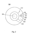
- FIG. 2 is a schematic picture of a rotatable microfluidic disc 200 of the types discussed aboveabove.
- a rotatable disc typically has a central recess 205 for a disc holder. Samples may be placed near the center of the disc and centrifugal forces, created as the disc rotates, may push them out through channels 210 cut into the plastic, circumventing the need to design sophisticated electrokinetic or mechanical pumping structures. Only one section 220 is depicted on the illustrated disc 200.
- a section on a disc is a group of microstructures 225 that are connected to a common distribution channel 230.
- a microstructure is a system of microchannels, which is used to perform a process protocol on a sample.
- a number of structures or channels 210 extend, for instance radially, from the common distribution channel 230 and ends in a detection position 240 where detection may occur.
- Inlet positions 250 are distributed along the channels.
- a small channel 255 extends from the inlet 250 and connects to said micro channel 210. Samples, liquids and reagent may be dispensed here.
- each of said stations is connected to the control unit 110 and controlled and monitored from the control unit 110 by means of a number of operations.
- a software operation is defined as a logical group of hardware instructions, which are performed to accomplish a certain function, such as:
- An operation may consist of a number of steps.
- a step is a non-dividable instruction, such as a ramp in a spin operation.
- a set can be constituted by putting together a number of these operations in a desired order.
- Such a set is defined as a method that gives the total processing of a microfluidic device in the instrument and controls all parts conducted within the instrument.
- the set/method thus prescribes a type of microfluidic device and defines a set of actions, operations. It may prescribe halting for conducting steps outside the instrument, for instance incubations at constant temperature when the method concerns cell culturing.
- the method may comprise one or more subsets of operations that can be iterated in a loop a predetermined number of times. Such a subset may for instance be that
- the present invention relates to a process for providing a dynamic method set including methods associated to a special microfluidic device type used in a microfluidic system. It is a generic tool in the meaning that it supports a method developer to build methods for in principle any application, i.e. it can support all operations that are to be performed within the instrument.
- the invention can be described as a Method Handler (MH), which consists of several parts used to check and create different methods.
- the part that creates methods can be called the Method Editor (ME). It is used to create a scheme of operations that together with the microfluidic device forms an application for a specific microfluidic device type.
- MH also checks if a method is executable on a specific instrument. This is done in a part called Batch Run (BR).
- BR Batch Run
- the method itself describes an application from a logical point of view, i.e. the sequence of operations, how to perform them, etc.
- the scheme of operations that builds up a method has no knowledge if it can be executed on a certain instrument.
- the ME is responsible for checking that a method is executable from a logical point of view, i.e. if the method complies with rules set up for a particular microfluidic device including also the application(s) for which the device is adapted. These rules will henceforth be called logical rules.
- the BR is responsible for checking if the method is executable on a specific instrument from a physical and chemical point of view and if the settings of the instrument are acceptable and appropriate.
- step 310 and 320 may require additional information or data, here defined as operation settings.
- Required operation settings associated to an operation may be inserted between step 310 and 320, as a step 315 (not shown in figure 3a ).
- the invented process can be performed on an ordinary personal computer having a display or screen and input means, for instance a mouse and a keyboard.
- the method handler comprises a user interface for displaying predetermined operations of stored predetermined microfluidic device operations on a display or screen.
- the user interface provides a window having a button or tab for each selectable operation. When the user selects an operation, he/she has only to point at the desired operation button and to click the button using a mouse button.
- the computer or processor collects the corresponding predetermined microfluidic device operations from a computer readable storage or memory or server or other medium in the order determined by the user/method developer, adding said collected predetermined operations in said order to a temporary set in a database or an allocated memory area in a computer readable storage or memory or server or other medium.
- the method handler software will inquire for completing information and instructions, operation settings, e.g. spinning velocity or spinning time.
- operation settings e.g. spinning velocity or spinning time.
- the method handler software will run an edit checking step for accepting or rejecting said temporary set of operations. Said edit checking step makes use of a set of rules and conditions related to the special microfluidic device type and to other logical rules e.g.
- the edit checking step will reject the temporary set or ask for completing information.
- the temporary set is accepted it is stored under a specific method name and in a format applicable for transfer to said dynamic method set.
- Said associated dynamic method set is dynamic in that the application specific methods and/or operations may be added or amended or deleted if needed.
- the invention uses a set of rules and conditions to determine if the method is executable. It is basically a check if all necessary information are in place.
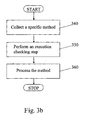
- the invented process may include an executing step (Batch Run) comprising the following steps, as illustrated in the flowchart in fig. 3b :
- the method handler software causes the computer to perform a collection of one set of microfluidic device type operations associated with the selected specific method name and an execution of a checking step by applying a set of rules and conditions related to the microfluidic system where the set of operations is to be processed. If the user has made mistakes, e.g. in filling in the completing information and instructions or the selected method is not applicable on the present system instrument or its configuration, the Batch Run checking step will reject the method.
- the things to check can be:
- the system can use the microfluidic device within the microfluidic system for processing the set of operations defined by the method.
- a method developer using the invented Method Handler tool may take following steps:
- the BR checking step includes checking that the transformed method is executable in the intended system.
- the invention also relates to a computer program product stored at a computer program product readable means, having thereon computer program code means, when said program is loaded, to make a computer to perform the process according to any of claims 1-5.
- the invention also relates to a computer program element for providing a dynamic method set including methods associated to a special microfluidic device type used in a microfluidic system.
- the computer program code comprises at least following computer executable computer program elements:
- computer program element may comprise one or more of the elements:
- the computer program element may also comprise an inquiring and acquiring element, said element being capable inquiring and acquiring required operation settings associated to a collected and added operation.
- the present invention also relates to a carrier having thereon at least one dynamic method set including methods associated to a special microfluidic device type used in a microfluidic system comprising at least one central processor and storage means for computer program code.
- Each method in said dynamic method set is accepted for a special Microfluidic device type and defined by a specific method name and said method comprises a number of operations causing the Microfluidic system to perform said operations in a predetermined order.
- the carrier may be a record medium, a computer memory, a Read-Only Memory or an electrical carrier signal.
- the carrier in particular if it is outside the system to be used, may comprise the method set stored in a formatted way, e.g. XML, that allows for a syntax check when the method is imported to the system.
- the process may also contain additional steps, for instance a step in which a method after the edit checking step, either before or after the storing step, is accepted in the sense that the method becomes static without possibility to further edit or remove it from the dynamic method set.
- the computer program product, the computer program element and the carrier may comprise the corresponding feature.
Landscapes
- Chemical & Material Sciences (AREA)
- Health & Medical Sciences (AREA)
- Chemical Kinetics & Catalysis (AREA)
- Analytical Chemistry (AREA)
- General Health & Medical Sciences (AREA)
- Organic Chemistry (AREA)
- Clinical Laboratory Science (AREA)
- Hematology (AREA)
- Dispersion Chemistry (AREA)
- Physics & Mathematics (AREA)
- Life Sciences & Earth Sciences (AREA)
- Biochemistry (AREA)
- General Physics & Mathematics (AREA)
- Immunology (AREA)
- Pathology (AREA)
- Automatic Analysis And Handling Materials Therefor (AREA)
- Physical Or Chemical Processes And Apparatus (AREA)
Abstract
Description
- The present invention relates to a process for providing a dynamic method set including methods associated to a special microfluidic device type used in a microfluidic system. The present invention also relates to a computer program product, a computer program element and a carrier comprising the computer program product.
- The term "microfluidic" refers to a system or device comprising one or a network of chambers and/or channels, which have micro scale dimensions, e.g., having at least one cross sectional dimension in the range from about 0,1 µm to about 500 µm. Microfluidic devices are often fabricated using photolithography, wet chemical etching, injection-molding, embossing, and other techniques similar to those employed in the semiconductor industry for producing the networks in uncovered form in a substrate. The uncovered network is subsequently covered by a top substrate. The resulting devices can be used to perform a variety of sophisticated chemical and biological analytical techniques.
- Microfluidic analytical systems have a number of advantages over conventional chemical or physical laboratory techniques. For example, microfluidic systems/devices are particularly well adapted for analyzing small sample sizes in the µl-range, typically making use of samples on the order of nanoliters (1-1000nl) and even picoliters (1-1000 pl). The channel defining substrates may be produced at relatively low cost, and the channels can be arranged to perform numerous analytical operations, including mixing, dispensing, valving, reactions, detections, electrophoresis, and the like. The analytical capabilities of microfluidic systems are generally enhanced by increasing the number and complexity of network channels, reaction chambers, and the like.
- Substantial advances have recently been made in the general areas of flow control and physical interactions between the samples and the supporting analytical structures.
- Flow control management may make use of a variety of mechanisms, including the patterned application of voltage, current, or electrical power to the substrate (for example, to induce and/or control electrokinetic flow or electrophoretic separations). Alternatively, fluid flows may be induced mechanically through the application of differential pressure, acoustic energy, or the like. Selective heating, cooling, exposure to light or other radiation, or other inputs may be provided at selected locations distributed about the substrate to promote the desired chemical and/or biological interactions. Similarly, measurements of light or other emissions, electrical/electrochemical signals, and pH may be taken from the substrate to provide analytical results. As work has progressed in each of these areas, the channel size has gradually decreased while the channel network has increased in complexity, significantly enhancing the overall capabilities of Microfluidic systems.
- The microfluidics technologies/devices are capable of controlling and transferring tiny quantities of liquids to allow biological assays to be integrated and accomplished on a small scale. The miniaturization of biological separation and assay techniques implies that multiple "experiments" can be accomplished on a "chip" small enough to fit in the palm of your hand. Tiny quantities of solvent, sample, and reagents are steered through narrow channels on the chip, where they are mixed and analyzed by such techniques as electrophoresis, fluorescence detection, immunoassay, or indeed almost any classical laboratory method.
- Today a number of products varying in many respects are available. Laboratory chips may be made from plastic, glass, quartz or even silicon. The fluid may be driven by spinning (centrifugal forces), capillarity in the network, mechanical pressure or vacuum pumps, inertia, or by one of several electrical methods; fluid flow can be diverted around the chip by mechanical valves, surface tension, voltage gradients, or even electromagnetic forces.
- In the technique of using centrifugal forces to drive the fluid a disc that can be spinned is used. Some discs have been of the same physical format as conventional CDs. Samples are placed at an inner position, e.g. near the center of the disc, and centrifugal forces, created as the disc rotates, push them to an outer position through channels cut into the plastic, circumventing the need to design sophisticated electrokinetic or mechanical pumping structures.
- As will become evident in the forth-coming description the present invention is in particular applicable to (but not limited to) micro-analysis systems that are based on micro-channels formed in a rotatable, usually plastic, disc, often called a "lab on a chip".
- Microfluidic devices/discs can be used to perform analysis and separation on small quantities of fluids. In order to reduce costs it is desirable that the discs should not be restricted to use with just one type of reagent or fluid but should be able to work with a variety of fluids.
- Furthermore it is often desirable during the preparation of samples that the disc permits the user to dispense accurate volumes of various predetermined combinations of fluids or samples without modifying the disc. Microanalysis devices for fluids provided in a rotatable disc are described e.g. in
WO-97/21090 WO-98/07019 WO-98/53311 WO-O1/46465 WO-O1/47638 WO-02/41997 WO-02/41998 - One general object of present invention is to increase the performance of a microfluidic system.
- A more specific object of the present invention is to provide powerful software tools for creating and performing various processes including sample preparation, treatment of liquids, various chemical and biochemical steps etc in a microfluidic device.
- The invention can be described shortly as a method-developing tool, which consists of several parts used to check and create different methods for microfluidic instruments. The part that creates methods can be called the Method Editor (ME). It is used to create a scheme of operations that together with the instrument builds up an application for a specific microfluidic device type. The method-developing tool also checks if a method is executable on a specific instrument. This is done in a part called Batch Run (BR).
- The above-mentioned objects are achieved by a process, a computer program product, a computer program element, and carrier according to the independent claims or by any other means suggested herein.
- Preferred embodiments are set forth in the dependent claims.
- A number of advantages are provided by the present invention. The process for developing methods for microfluidic systems is faster, more cost effective, more systematic and logical. The invention also offers a good survey and handling of available operations and developed methods.
-
-
Fig. 1 is a block diagram depicting schematically a microfluidic system. -
Fig. 2 is a schematic picture of a microfluidic device in form of a disc. -
Fig. 3a is a flowchart illustrating an embodiment of the process according to the invention. -
Fig. 3b is a flowchart illustrating an embodiment of a process that could be added to the process according toFig. 3a . - The present invention relates to a process for providing a dynamic method set including methods associated to a special microfluidic device type used in a microfluidic system. The present invention also relates to a computer program product, a computer program element and a carrier comprising the computer program product.
- A microfluidic system may comprise a control unit and a microfluidic instrument. Such a system is called a Stand Alone System. Each system has its own data and operates completely stand alone. The interaction with the system may be performed at an associated Personal Computer (PC).
- Another system can be considered as a group of instruments plus a common persistent storage location, e.g. database. Many instruments can operate on the same set of data (Method Data, Microfluidic Device Data, etc). All interaction with the system needs to be performed at an instrument connected computer. This second system is often called a Distributed Database Solution.
- In a third variant, the distributed solution, the system is considered as a group of instruments, a common storage persistent storage location (database), and a number of clients. With this solution the same functionality as in the above-mentioned Distributed Database Solution is reached. In addition there will be a possibility to interact with the system from non instrument connected computers. The solution may provide additional functionalities, e.g.:
- Remote monitoring of instruments (checking of process status, alarms etc).
- Perform functions that are not instrument specific (Method Development, Evaluation of processed data, etc )
- An operator/user can control and monitor the performance of the microfluidic instrument from the control unit. The microfluidic instrument comprises a number of different stations, each station being capable of performing one or a number of defined operations. Different types of microfluidic instruments consist of different kinds of stations or number of stations. Therefore, some operations will not be provided for or applicable on a certain type of microfluidic instrument.
- The operations are initiated from the control unit.
-
Fig. 1 is a block diagram depicting schematically amicrofluidic system 100 that includes acontrol unit 110 and an instrument 120 comprising a sample andreagent station 130, awash station 140, aliquid transfer station 150, at least onestation 160 for implementing transport of liquid within the microfluidic device e.g., a spinner station and adetector station 170. Two or more stations may be integrated with each other and appear physically as one station that is capable of performing the functions of the integrated stations. - The
control unit 110 may be one or more computers outside the instrument and/or one or more central processors within the instrument. The control unit is connected to the instrument 120 and its different stations via a conductor ordata bus 180 and operation orders are transmitted either as electrical or optical signals or included in a suitable predetermined protocol to hardware circuits distributed between the stations. - The sample and
reagent station 130 typically comprises means for storing samples, reagents or other liquids. Said samples, reagents or other liquids is stored in some kind of container, such as a micro plate or multiwell plate, a test tube rack or a test tube. Said plate is designed as a matrix of small containers or wells. Said plate can have different sizes depending on the number of wells. The container may be loosely fixed at a container holder, for instance a so called carousel, which is a circular revolving plate. - The
liquid transfer station 150 may have arobot 150a that transfer at least one sample or any other predetermined liquid aliquot at a time from the sample andreagent station 130 to a microfluidic device, for instance in the form of a disc that can be spinned. The station have means for transfer of liquid samples, and other liquids, for instance a number of injection needles connected to syringe pumps or a number of solid pins may be used for the transfer of samples. Said needles and pins may be configured in different numbers of rows and columns having different distance between the tips in both directions. Another alternative is a microdispensor for dispensing droplets, e.g. the microdispensor described inWO 9701085 - Said needles and pins may or may not be washed in a wash solution between the transfers of samples and reagents. Washing is done by means placed in a
wash station 140. - The liquids dispensed to a microfluidic device are transported within the device by means associated with the
station 160 for implementing liquid transport, e.g. of the types discussed above. This station may be a spinner station in case the microfludic device is adapted to permit liquid transport caused by spinning. The result of a process carried out within the microfluidic device is determined by means for detecting (a detector) which is located in adetector station 170. -
Fig. 2 is a schematic picture of a rotatablemicrofluidic disc 200 of the types discussed aboveabove. A rotatable disc typically has acentral recess 205 for a disc holder. Samples may be placed near the center of the disc and centrifugal forces, created as the disc rotates, may push them out throughchannels 210 cut into the plastic, circumventing the need to design sophisticated electrokinetic or mechanical pumping structures. Only onesection 220 is depicted on the illustrateddisc 200. A section on a disc is a group ofmicrostructures 225 that are connected to acommon distribution channel 230. A microstructure is a system of microchannels, which is used to perform a process protocol on a sample. A number of structures orchannels 210 extend, for instance radially, from thecommon distribution channel 230 and ends in adetection position 240 where detection may occur. Inlet positions 250 are distributed along the channels. Asmall channel 255 extends from theinlet 250 and connects to saidmicro channel 210. Samples, liquids and reagent may be dispensed here. - As shown in
fig. 1 , each of said stations is connected to thecontrol unit 110 and controlled and monitored from thecontrol unit 110 by means of a number of operations. A software operation is defined as a logical group of hardware instructions, which are performed to accomplish a certain function, such as: - Implementing transport of liquid, for instance spinning the device if the device is in the form of a disc that can be spinned in order to induce liquid flow.
- Sample transfer to a specific common distribution channel or a specific microstructure.
- Reagent transfer to a specific common distribution channel or a specific microstructure.
- Position the microfluidic device.
- Incubate the liquids at a certain position in the microstructures for a specific time.
- Detection, i.e. detection of the results of the method carried out in the microfluidic device.
- Wash, for instance of dispensing means (needles, syringes etc)
- An operation may consist of a number of steps. A step is a non-dividable instruction, such as a ramp in a spin operation. A set can be constituted by putting together a number of these operations in a desired order. Such a set is defined as a method that gives the total processing of a microfluidic device in the instrument and controls all parts conducted within the instrument. The set/method thus prescribes a type of microfluidic device and defines a set of actions, operations. It may prescribe halting for conducting steps outside the instrument, for instance incubations at constant temperature when the method concerns cell culturing. The method may comprise one or more subsets of operations that can be iterated in a loop a predetermined number of times. Such a subset may for instance be that
- e) a selected series (subset) of operations is performed on a certain number selected microchannel at a time until a predetermined total number of microchannel structures has ben subjected to the subset,
- e) the same subset of operations is repeated on the same microchannel structure(s), e.g. a particular part of a washing procedure for conditioning or cleaning the microchannel structure(s) or their content, etc.
- As stated above, the present invention relates to a process for providing a dynamic method set including methods associated to a special microfluidic device type used in a microfluidic system. It is a generic tool in the meaning that it supports a method developer to build methods for in principle any application, i.e. it can support all operations that are to be performed within the instrument. The invention can be described as a Method Handler (MH), which consists of several parts used to check and create different methods. The part that creates methods can be called the Method Editor (ME). It is used to create a scheme of operations that together with the microfluidic device forms an application for a specific microfluidic device type. MH also checks if a method is executable on a specific instrument. This is done in a part called Batch Run (BR).
- The method itself describes an application from a logical point of view, i.e. the sequence of operations, how to perform them, etc. The scheme of operations that builds up a method has no knowledge if it can be executed on a certain instrument. The ME is responsible for checking that a method is executable from a logical point of view, i.e. if the method complies with rules set up for a particular microfluidic device including also the application(s) for which the device is adapted. These rules will henceforth be called logical rules.
- The BR is responsible for checking if the method is executable on a specific instrument from a physical and chemical point of view and if the settings of the instrument are acceptable and appropriate.
- An embodiment of the Method Handling tool and the process according to the invention will now be described in more detail with reference to the flowchart in
fig. 3a . The process includes following steps: - step 300: displaying predetermined operations of stored predetermined microfluidic device operations on a display or screen;
- step 310: collecting a number of predetermined operations from said stored and displayed predetermined microfluidic device operations and adding said collected predetermined operations to a temporary set;
- step 320: running an edit checking step for accepting or rejecting said temporary set of operations, wherein said edit checking step makes use of a set of rules related to the special microfluidic device type and to other logical rules;
- step 330: storing said checked and accepted microfluidic device type set of operations, i.e. said temporary set in accepted form, under a specific method name and in a format applicable for transfer to said dynamic method set.
- Further, some of the collected and added operations may require additional information or data, here defined as operation settings. Required operation settings associated to an operation are inquired and acquired may be inserted between
step figure 3a ). - The invented process can be performed on an ordinary personal computer having a display or screen and input means, for instance a mouse and a keyboard. The method handler comprises a user interface for displaying predetermined operations of stored predetermined microfluidic device operations on a display or screen. The user interface provides a window having a button or tab for each selectable operation. When the user selects an operation, he/she has only to point at the desired operation button and to click the button using a mouse button. As the user selects operations, the computer or processor collects the corresponding predetermined microfluidic device operations from a computer readable storage or memory or server or other medium in the order determined by the user/method developer, adding said collected predetermined operations in said order to a temporary set in a database or an allocated memory area in a computer readable storage or memory or server or other medium. For some of the operations, the method handler software will inquire for completing information and instructions, operation settings, e.g. spinning velocity or spinning time. When the user is finished with the selection of operation, the method handler software will run an edit checking step for accepting or rejecting said temporary set of operations. Said edit checking step makes use of a set of rules and conditions related to the special microfluidic device type and to other logical rules e.g. related to the application intended. If the user has made mistakes in filling in the completing information, such as operation settings, and instructions, the edit checking step will reject the temporary set or ask for completing information. When the temporary set is accepted it is stored under a specific method name and in a format applicable for transfer to said dynamic method set.
- Said associated dynamic method set is dynamic in that the application specific methods and/or operations may be added or amended or deleted if needed.
- As stated above, the invention uses a set of rules and conditions to determine if the method is executable. It is basically a check if all necessary information are in place.
- Here follows, as an example, an non-exhaustive list of suitable rules:
- If spin operation is selected, is spin step defined?
- Are positions on the microfluidic device selected?
- Are necessary liquids defined?
- Further, the invented process may include an executing step (Batch Run) comprising the following steps, as illustrated in the flowchart in
fig. 3b : - step 340: collecting one set of microfluidic device type operations associated with a specific method name;
- step 350: performing a checking step to see if the collected set is executable (execution checking step) by applying a set of rules and conditions related to the microfluidic system where the set of operations is to be processed, and;
- step 360: processing the microfluidic device with the microfluidic system using the collected set of operations.
- When the user (method developer) selects a specific method, the user will initiate an executing step of the method handler tool. The method handler software causes the computer to perform a collection of one set of microfluidic device type operations associated with the selected specific method name and an execution of a checking step by applying a set of rules and conditions related to the microfluidic system where the set of operations is to be processed. If the user has made mistakes, e.g. in filling in the completing information and instructions or the selected method is not applicable on the present system instrument or its configuration, the Batch Run checking step will reject the method. The things to check can be:
- - Does the instrument have the right hardware and hardware configuration and settings to perform the different operations?
- - Is the method executable? I.e. does it contain all information needed to execute the method.
- - Have the right liquids been loaded?
- If the method is accepted, the system can use the microfluidic device within the microfluidic system for processing the set of operations defined by the method.
- Here follows a short presentation of how the Method Handler tool is used. A method developer using the invented Method Handler tool may take following steps:
- Chose type of microfluidic device;
- Build up the method (or sequence of operations) from information related to the type of Microfluidic device;
- Apply a set of rules in ME checking step;
- Save checked method and then distribute storage medium with checked method or distribute checked method via internet, e.g. user may download from provider server, to user/customer.
- When the method shall be executed the MH checks, by applying Batch Run -rules, if the connected instrument can process the selected method. This step is called the BR checking step or execution checking step and makes use of a rules that are related to the system including the instrument and the microfluidic device contemplated. If the method is accepted it is only to run and use the method.
- If a user receives the method stored at a storage medium or downloads it from internet and transforms it to a useful format, the BR checking step includes checking that the transformed method is executable in the intended system.
- The invention also relates to a computer program product stored at a computer program product readable means, having thereon computer program code means, when said program is loaded, to make a computer to perform the process according to any of claims 1-5.
- The invention also relates to a computer program element for providing a dynamic method set including methods associated to a special microfluidic device type used in a microfluidic system. The computer program code comprises at least following computer executable computer program elements:
- a user interface element, said user interface element being capable of displaying predetermined operations stored in a predetermined microfluidic device operations storage;
- an operation collecting element, said collecting element being capable of collecting a number of predetermined operations from said stored and displayed predetermined microfluidic device operations;
- an adding element, said adding element being capable of adding said collected predetermined operations to a temporary set;
- an edit checking step element, said edit checking element being capable of running an edit checking step for accepting or rejecting said temporary set of operations, wherein said edit checking step makes use of a set of rules related to the special microfluidic device type and to other logical rules;
- a storing element, said storing element being capable of storing said checked and accepted microfluidic device type set of operations under a specific method name and in a format applicable for transfer to said dynamic method set.
- Further, the computer program element may comprise one or more of the elements:
- a method collecting element, said element being capable of collecting one set of microfluidic device type operations associated with a specific method name;
- an execution checking step element, said element being capable of performing the execution checking step by applying a set of rules and conditions related to the microfluidic system where the set of operations is to be processed, and;
- a processing step element, said element being capable of processing the microfluidic device with the microfluidic system using the set of operations.
- The computer program element may also comprise an inquiring and acquiring element, said element being capable inquiring and acquiring required operation settings associated to a collected and added operation.
- The present invention also relates to a carrier having thereon at least one dynamic method set including methods associated to a special microfluidic device type used in a microfluidic system comprising at least one central processor and storage means for computer program code. Each method in said dynamic method set is accepted for a special Microfluidic device type and defined by a specific method name and said method comprises a number of operations causing the Microfluidic system to perform said operations in a predetermined order. The carrier may be a record medium, a computer memory, a Read-Only Memory or an electrical carrier signal. The carrier, in particular if it is outside the system to be used, may comprise the method set stored in a formatted way, e.g. XML, that allows for a syntax check when the method is imported to the system.
- The process may also contain additional steps, for instance a step in which a method after the edit checking step, either before or after the storing step, is accepted in the sense that the method becomes static without possibility to further edit or remove it from the dynamic method set. The computer program product, the computer program element and the carrier may comprise the corresponding feature.
- The present invention is not limited to the above-described preferred embodiments. Various alternatives, modifications and equivalents may be used. Therefore, the above embodiments should not be taken as limiting the scope of the invention, which is defined by the appending claims.
Claims (14)
- Process for providing a dynamic method set including methods associated to a special microfluidic device type used in a microfluidic system comprising at least one central processor and storage means for computer program code, characterized in that the process includes following steps:- displaying predetermined operations of stored predetermined microfluidic device operations;- collecting a number of predetermined operations from said stored and displayed predetermined microfluidic device operations and adding said collected predetermined operations to a temporary set;- running an edit checking step for accepting or rejecting said temporary set of operations, wherein said edit checking step makes use of a set of rules related to the special microfluidic device type and to other logical rules;- storing said checked and accepted microfluidic device type set of operations under a specific method name and in a format applicable for transfer to said dynamic method set.
- Process according to claim 1, characterized in that said associated dynamic method set is dynamic in that application specific methods and/or operations may be added/amended/deleted if needed.
- Process according to claim 1, characterized in that the process further includes an execution step comprising the following steps:- collecting one set of microfluidic device type operations associated with a specific method name;- performing an executing checking step by applying a set of rules and conditions related to the microfluidic system where the set of operations is to be processed, and;- processing the microfluidic device with the microfluidic system using the set of operations.
- Process according to claim 1, characterized in that said operations can be one of the following operations:- Spinning the microfluidic device; or- Sample transfer to a specific common channel or microstructure; or- Reagent transfer to a specific common channel or microstructure; or- Position the microfluidic device; or- Incubate or hold the microfluidic device for a specific time; or- Detection; or- Wash.
- Process according to claim 1, characterized in that the process includes the following step:- inquiring and acquiring of required operation settings associated to a collected and added operation.
- Computer program product stored at a computer program product readable means, characterized in that said program product is adapted to perform the process according to any of claims 1-5.
- A computer program element for providing a dynamic method set including methods associated to a special microfluidic device type used in a microfluidic system, characterized in that the computer program code comprises at least following computer executable computer program elements:- a user interface element, said user interface element being capable of displaying predetermined operations stored in a predetermined microfluidic device operations storage;- an operation collecting element, said collecting element being capable of collecting a number of predetermined operations from said stored and displayed predetermined microfluidic device operations;- an adding element, said adding element being capable of adding said collected predetermined operations to a temporary set;- an edit checking step element, said edit checking element being capable of running an edit checking step for accepting or rejecting said temporary set of operations, wherein said edit checking step makes use of a set of rules related to the special microfluidic device type and to other logical rules;- a storing element, said storing element being capable of storing said checked and accepted microfluidic device type set of operations under a specific method name and in a format applicable for transfer to said dynamic method set.
- A computer program element according to claim 7, characterized by:- a method collecting element, said element being capable of collecting one set of microfluidic device type operations associated with a specific method name;- an executing checking step element, said element being capable of performing the execution checking step by applying a set of rules and conditions related to the microfluidic system where the set of operations is to be processed, and;- a processing step element, said element being capable of processing the microfluidic device with the microfluidic system using the set of operations.
- A computer program element according to claim 7, characterized by:- an inquiring and acquiring element, said element being capable inquiring and acquiring required operation settings associated to a collected and added operation.
- A carrier having thereon at least one dynamic method set including methods associated to a special microfluidic device type used in a microfluidic system comprising at least one central processor and storage means for computer program code, characterized in that, each method in said dynamic method set is accepted for a special microfluidic device type and defined by a specific method name and said method comprises a number of operations causing the microfluidic system to perform said operations in a predetermined order.
- The carrier according to claim 10, characterized in that the carrier is a record medium.
- The carrier according to claim 10, characterized in that the carrier is a computer memory.
- The carrier according to claim 10, characterized in that the carrier is a Read-Only Memory.
- The carrier according to claim 10, characterized in that the carrier is an electrical carrier signal.
Applications Claiming Priority (5)
| Application Number | Priority Date | Filing Date | Title |
|---|---|---|---|
| US953155 | 1978-10-19 | ||
| SE0103087A SE0103087D0 (en) | 2001-09-17 | 2001-09-17 | Method editor |
| US09/953,155 US6728644B2 (en) | 2001-09-17 | 2001-09-17 | Method editor |
| SE0103087 | 2001-09-17 | ||
| PCT/SE2002/001606 WO2003025585A1 (en) | 2001-09-17 | 2002-09-09 | Method handler for microfluidic instruments |
Publications (2)
| Publication Number | Publication Date |
|---|---|
| EP1428031A1 EP1428031A1 (en) | 2004-06-16 |
| EP1428031B1 true EP1428031B1 (en) | 2010-07-28 |
Family
ID=26655550
Family Applications (1)
| Application Number | Title | Priority Date | Filing Date |
|---|---|---|---|
| EP02765748A Expired - Lifetime EP1428031B1 (en) | 2001-09-17 | 2002-09-09 | Method handler for microfluidic instruments |
Country Status (5)
| Country | Link |
|---|---|
| EP (1) | EP1428031B1 (en) |
| JP (1) | JP2005503560A (en) |
| AT (1) | ATE475890T1 (en) |
| DE (1) | DE60237160D1 (en) |
| WO (1) | WO2003025585A1 (en) |
Families Citing this family (4)
| Publication number | Priority date | Publication date | Assignee | Title |
|---|---|---|---|---|
| SE0300822D0 (en) | 2003-03-23 | 2003-03-23 | Gyros Ab | A collection of Micro Scale Devices |
| WO2007069940A1 (en) | 2005-12-12 | 2007-06-21 | Gyros Patent Ab | Microfluidic assays and microfluidic devices |
| US8868353B2 (en) | 2007-02-02 | 2014-10-21 | Beckman Coulter, Inc. | System and method for testing autoverification rules |
| US8112232B2 (en) | 2007-02-02 | 2012-02-07 | Beckman Coulter, Inc. | System and method for autoverifying laboratory test results |
Family Cites Families (5)
| Publication number | Priority date | Publication date | Assignee | Title |
|---|---|---|---|---|
| US5355439A (en) * | 1991-08-05 | 1994-10-11 | Bio Tek Instruments | Method and apparatus for automated tissue assay |
| AU702403B2 (en) * | 1995-12-05 | 1999-02-18 | Gamera Bioscience | Devices and methods for using centripetal acceleration to drive fluid movement in a microfluidics system with on-board informatics |
| US6294063B1 (en) * | 1999-02-12 | 2001-09-25 | Board Of Regents, The University Of Texas System | Method and apparatus for programmable fluidic processing |
| US6500323B1 (en) * | 1999-03-26 | 2002-12-31 | Caliper Technologies Corp. | Methods and software for designing microfluidic devices |
| US7062418B2 (en) * | 2000-06-27 | 2006-06-13 | Fluidigm Corporation | Computer aided design method and system for developing a microfluidic system |
-
2002
- 2002-09-09 JP JP2003529163A patent/JP2005503560A/en active Pending
- 2002-09-09 DE DE60237160T patent/DE60237160D1/en not_active Expired - Lifetime
- 2002-09-09 WO PCT/SE2002/001606 patent/WO2003025585A1/en not_active Ceased
- 2002-09-09 AT AT02765748T patent/ATE475890T1/en not_active IP Right Cessation
- 2002-09-09 EP EP02765748A patent/EP1428031B1/en not_active Expired - Lifetime
Also Published As
| Publication number | Publication date |
|---|---|
| EP1428031A1 (en) | 2004-06-16 |
| JP2005503560A (en) | 2005-02-03 |
| WO2003025585A1 (en) | 2003-03-27 |
| ATE475890T1 (en) | 2010-08-15 |
| DE60237160D1 (en) | 2010-09-09 |
Similar Documents
| Publication | Publication Date | Title |
|---|---|---|
| US6728644B2 (en) | Method editor | |
| US6992278B2 (en) | Homing process | |
| DE69634490T2 (en) | APPARATUS AND METHOD FOR MOVING FLUIDS BY CENTRIFUGAL ACCELERATION IN AUTOMATIC LABORATORY TREATMENT | |
| Ríos et al. | Miniaturization through lab-on-a-chip: Utopia or reality for routine laboratories? A review | |
| Song et al. | Millisecond kinetics on a microfluidic chip using nanoliters of reagents | |
| Fitzgerald | Making every nanoliter count: microfluidics devices promise great potential in small packages.(Lab Consumer) | |
| US6366924B1 (en) | Distributed database for analytical instruments | |
| US7476361B2 (en) | Microfluidics devices and methods of diluting samples and reagents | |
| Paegel et al. | Microfluidic serial dilution circuit | |
| Wijethunga et al. | On-chip drop-to-drop liquid microextraction coupled with real-time concentration monitoring technique | |
| Steigert et al. | Integrated sample preparation, reaction, and detection on a high-frequency centrifugal microfluidic platform | |
| US20020151078A1 (en) | Microfluidics devices and methods for high throughput screening | |
| US20050069913A1 (en) | Devices and methods for using centripetal acceleration to drive fluid movement in a microfluidics system | |
| WO2000070490A2 (en) | Methods, apparatus, articles of manufacture, and user interfaces for performing automated biological assay preparation and macromolecule purification | |
| JP2004501360A (en) | Microfluidic devices and methods for high-throughput screening | |
| Amin et al. | Software-programmable continuous-flow multi-purpose lab-on-a-chip | |
| US20080138247A1 (en) | Liquid Detection and Confidence Determination | |
| EP1577010A2 (en) | Microsystem platform and its use | |
| US20070275426A1 (en) | Disk-like microfluidic structure for generating diffrent concentration fluid mixtures | |
| EP1888237B1 (en) | Method for determining the identity of a microfluidic disc and microfluidic disc | |
| EP1428031A1 (en) | Method handler for microfluidic instruments | |
| CN210206903U (en) | Microfluidic chip assembly | |
| Meldrum et al. | Automated, integrated modules for fluid handling, thermal cycling and purification of DNA samples for high throughput sequencing and analysis | |
| Powell et al. | Microflow-based automated chemistries: application to protein sequencing | |
| Dhal et al. | A new move toward parallel assay operations in a restricted sized chip in digital microfluidics |
Legal Events
| Date | Code | Title | Description |
|---|---|---|---|
| PUAI | Public reference made under article 153(3) epc to a published international application that has entered the european phase |
Free format text: ORIGINAL CODE: 0009012 |
|
| 17P | Request for examination filed |
Effective date: 20040325 |
|
| AK | Designated contracting states |
Kind code of ref document: A1 Designated state(s): AT BE BG CH CY CZ DE DK EE ES FI FR GB GR IE IT LI LU MC NL PT SE SK TR |
|
| RAP1 | Party data changed (applicant data changed or rights of an application transferred) |
Owner name: GYROS PATENT AB |
|
| GRAP | Despatch of communication of intention to grant a patent |
Free format text: ORIGINAL CODE: EPIDOSNIGR1 |
|
| GRAS | Grant fee paid |
Free format text: ORIGINAL CODE: EPIDOSNIGR3 |
|
| GRAA | (expected) grant |
Free format text: ORIGINAL CODE: 0009210 |
|
| AK | Designated contracting states |
Kind code of ref document: B1 Designated state(s): AT BE BG CH CY CZ DE DK EE ES FI FR GB GR IE IT LI LU MC NL PT SE SK TR |
|
| REG | Reference to a national code |
Ref country code: GB Ref legal event code: FG4D |
|
| REG | Reference to a national code |
Ref country code: CH Ref legal event code: EP |
|
| REG | Reference to a national code |
Ref country code: IE Ref legal event code: FG4D |
|
| REF | Corresponds to: |
Ref document number: 60237160 Country of ref document: DE Date of ref document: 20100909 Kind code of ref document: P |
|
| REG | Reference to a national code |
Ref country code: CH Ref legal event code: NV Representative=s name: ISLER & PEDRAZZINI AG |
|
| REG | Reference to a national code |
Ref country code: NL Ref legal event code: VDEP Effective date: 20100728 |
|
| PG25 | Lapsed in a contracting state [announced via postgrant information from national office to epo] |
Ref country code: FI Free format text: LAPSE BECAUSE OF FAILURE TO SUBMIT A TRANSLATION OF THE DESCRIPTION OR TO PAY THE FEE WITHIN THE PRESCRIBED TIME-LIMIT Effective date: 20100728 Ref country code: AT Free format text: LAPSE BECAUSE OF FAILURE TO SUBMIT A TRANSLATION OF THE DESCRIPTION OR TO PAY THE FEE WITHIN THE PRESCRIBED TIME-LIMIT Effective date: 20100728 Ref country code: NL Free format text: LAPSE BECAUSE OF FAILURE TO SUBMIT A TRANSLATION OF THE DESCRIPTION OR TO PAY THE FEE WITHIN THE PRESCRIBED TIME-LIMIT Effective date: 20100728 |
|
| PG25 | Lapsed in a contracting state [announced via postgrant information from national office to epo] |
Ref country code: PT Free format text: LAPSE BECAUSE OF FAILURE TO SUBMIT A TRANSLATION OF THE DESCRIPTION OR TO PAY THE FEE WITHIN THE PRESCRIBED TIME-LIMIT Effective date: 20101129 Ref country code: CY Free format text: LAPSE BECAUSE OF FAILURE TO SUBMIT A TRANSLATION OF THE DESCRIPTION OR TO PAY THE FEE WITHIN THE PRESCRIBED TIME-LIMIT Effective date: 20100728 Ref country code: BG Free format text: LAPSE BECAUSE OF FAILURE TO SUBMIT A TRANSLATION OF THE DESCRIPTION OR TO PAY THE FEE WITHIN THE PRESCRIBED TIME-LIMIT Effective date: 20101028 |
|
| PGFP | Annual fee paid to national office [announced via postgrant information from national office to epo] |
Ref country code: DE Payment date: 20101126 Year of fee payment: 9 |
|
| PG25 | Lapsed in a contracting state [announced via postgrant information from national office to epo] |
Ref country code: SE Free format text: LAPSE BECAUSE OF FAILURE TO SUBMIT A TRANSLATION OF THE DESCRIPTION OR TO PAY THE FEE WITHIN THE PRESCRIBED TIME-LIMIT Effective date: 20100728 Ref country code: BE Free format text: LAPSE BECAUSE OF FAILURE TO SUBMIT A TRANSLATION OF THE DESCRIPTION OR TO PAY THE FEE WITHIN THE PRESCRIBED TIME-LIMIT Effective date: 20100728 Ref country code: GR Free format text: LAPSE BECAUSE OF FAILURE TO SUBMIT A TRANSLATION OF THE DESCRIPTION OR TO PAY THE FEE WITHIN THE PRESCRIBED TIME-LIMIT Effective date: 20101029 |
|
| PG25 | Lapsed in a contracting state [announced via postgrant information from national office to epo] |
Ref country code: MC Free format text: LAPSE BECAUSE OF NON-PAYMENT OF DUE FEES Effective date: 20100930 Ref country code: DK Free format text: LAPSE BECAUSE OF FAILURE TO SUBMIT A TRANSLATION OF THE DESCRIPTION OR TO PAY THE FEE WITHIN THE PRESCRIBED TIME-LIMIT Effective date: 20100728 |
|
| PG25 | Lapsed in a contracting state [announced via postgrant information from national office to epo] |
Ref country code: EE Free format text: LAPSE BECAUSE OF FAILURE TO SUBMIT A TRANSLATION OF THE DESCRIPTION OR TO PAY THE FEE WITHIN THE PRESCRIBED TIME-LIMIT Effective date: 20100728 Ref country code: SK Free format text: LAPSE BECAUSE OF FAILURE TO SUBMIT A TRANSLATION OF THE DESCRIPTION OR TO PAY THE FEE WITHIN THE PRESCRIBED TIME-LIMIT Effective date: 20100728 Ref country code: IT Free format text: LAPSE BECAUSE OF FAILURE TO SUBMIT A TRANSLATION OF THE DESCRIPTION OR TO PAY THE FEE WITHIN THE PRESCRIBED TIME-LIMIT Effective date: 20100728 Ref country code: CZ Free format text: LAPSE BECAUSE OF FAILURE TO SUBMIT A TRANSLATION OF THE DESCRIPTION OR TO PAY THE FEE WITHIN THE PRESCRIBED TIME-LIMIT Effective date: 20100728 |
|
| PLBE | No opposition filed within time limit |
Free format text: ORIGINAL CODE: 0009261 |
|
| STAA | Information on the status of an ep patent application or granted ep patent |
Free format text: STATUS: NO OPPOSITION FILED WITHIN TIME LIMIT |
|
| PG25 | Lapsed in a contracting state [announced via postgrant information from national office to epo] |
Ref country code: ES Free format text: LAPSE BECAUSE OF FAILURE TO SUBMIT A TRANSLATION OF THE DESCRIPTION OR TO PAY THE FEE WITHIN THE PRESCRIBED TIME-LIMIT Effective date: 20101108 |
|
| 26N | No opposition filed |
Effective date: 20110429 |
|
| PG25 | Lapsed in a contracting state [announced via postgrant information from national office to epo] |
Ref country code: IE Free format text: LAPSE BECAUSE OF NON-PAYMENT OF DUE FEES Effective date: 20100909 |
|
| REG | Reference to a national code |
Ref country code: DE Ref legal event code: R097 Ref document number: 60237160 Country of ref document: DE Effective date: 20110429 |
|
| PGFP | Annual fee paid to national office [announced via postgrant information from national office to epo] |
Ref country code: CH Payment date: 20110914 Year of fee payment: 10 |
|
| PGFP | Annual fee paid to national office [announced via postgrant information from national office to epo] |
Ref country code: GB Payment date: 20110928 Year of fee payment: 10 |
|
| PGFP | Annual fee paid to national office [announced via postgrant information from national office to epo] |
Ref country code: FR Payment date: 20111012 Year of fee payment: 10 |
|
| PG25 | Lapsed in a contracting state [announced via postgrant information from national office to epo] |
Ref country code: LU Free format text: LAPSE BECAUSE OF NON-PAYMENT OF DUE FEES Effective date: 20100909 |
|
| PG25 | Lapsed in a contracting state [announced via postgrant information from national office to epo] |
Ref country code: TR Free format text: LAPSE BECAUSE OF FAILURE TO SUBMIT A TRANSLATION OF THE DESCRIPTION OR TO PAY THE FEE WITHIN THE PRESCRIBED TIME-LIMIT Effective date: 20100728 |
|
| REG | Reference to a national code |
Ref country code: CH Ref legal event code: PL |
|
| GBPC | Gb: european patent ceased through non-payment of renewal fee |
Effective date: 20120909 |
|
| REG | Reference to a national code |
Ref country code: FR Ref legal event code: ST Effective date: 20130531 |
|
| PG25 | Lapsed in a contracting state [announced via postgrant information from national office to epo] |
Ref country code: LI Free format text: LAPSE BECAUSE OF NON-PAYMENT OF DUE FEES Effective date: 20120930 Ref country code: CH Free format text: LAPSE BECAUSE OF NON-PAYMENT OF DUE FEES Effective date: 20120930 Ref country code: GB Free format text: LAPSE BECAUSE OF NON-PAYMENT OF DUE FEES Effective date: 20120909 Ref country code: DE Free format text: LAPSE BECAUSE OF NON-PAYMENT OF DUE FEES Effective date: 20130403 |
|
| REG | Reference to a national code |
Ref country code: DE Ref legal event code: R119 Ref document number: 60237160 Country of ref document: DE Effective date: 20130403 |
|
| PG25 | Lapsed in a contracting state [announced via postgrant information from national office to epo] |
Ref country code: FR Free format text: LAPSE BECAUSE OF NON-PAYMENT OF DUE FEES Effective date: 20121001 |