EP1427915B1 - Turbine no-load speed limiter - Google Patents
Turbine no-load speed limiter Download PDFInfo
- Publication number
- EP1427915B1 EP1427915B1 EP02807453A EP02807453A EP1427915B1 EP 1427915 B1 EP1427915 B1 EP 1427915B1 EP 02807453 A EP02807453 A EP 02807453A EP 02807453 A EP02807453 A EP 02807453A EP 1427915 B1 EP1427915 B1 EP 1427915B1
- Authority
- EP
- European Patent Office
- Prior art keywords
- turbine
- rotor
- speed
- spoilers
- passageway
- Prior art date
- Legal status (The legal status is an assumption and is not a legal conclusion. Google has not performed a legal analysis and makes no representation as to the accuracy of the status listed.)
- Expired - Lifetime
Links
- 239000012530 fluid Substances 0.000 claims abstract description 23
- 239000007858 starting material Substances 0.000 claims abstract description 22
- 238000000034 method Methods 0.000 claims description 2
- 230000001965 increasing effect Effects 0.000 description 3
- 230000009467 reduction Effects 0.000 description 2
- 230000008859 change Effects 0.000 description 1
- 230000005465 channeling Effects 0.000 description 1
- 230000003247 decreasing effect Effects 0.000 description 1
- 230000002708 enhancing effect Effects 0.000 description 1
- 230000007246 mechanism Effects 0.000 description 1
- 230000004048 modification Effects 0.000 description 1
- 238000012986 modification Methods 0.000 description 1
Images
Classifications
-
- F—MECHANICAL ENGINEERING; LIGHTING; HEATING; WEAPONS; BLASTING
- F02—COMBUSTION ENGINES; HOT-GAS OR COMBUSTION-PRODUCT ENGINE PLANTS
- F02C—GAS-TURBINE PLANTS; AIR INTAKES FOR JET-PROPULSION PLANTS; CONTROLLING FUEL SUPPLY IN AIR-BREATHING JET-PROPULSION PLANTS
- F02C7/00—Features, components parts, details or accessories, not provided for in, or of interest apart form groups F02C1/00 - F02C6/00; Air intakes for jet-propulsion plants
- F02C7/26—Starting; Ignition
- F02C7/268—Starting drives for the rotor, acting directly on the rotor of the gas turbine to be started
- F02C7/275—Mechanical drives
- F02C7/277—Mechanical drives the starter being a separate turbine
-
- F—MECHANICAL ENGINEERING; LIGHTING; HEATING; WEAPONS; BLASTING
- F05—INDEXING SCHEMES RELATING TO ENGINES OR PUMPS IN VARIOUS SUBCLASSES OF CLASSES F01-F04
- F05D—INDEXING SCHEME FOR ASPECTS RELATING TO NON-POSITIVE-DISPLACEMENT MACHINES OR ENGINES, GAS-TURBINES OR JET-PROPULSION PLANTS
- F05D2240/00—Components
- F05D2240/10—Stators
- F05D2240/12—Fluid guiding means, e.g. vanes
- F05D2240/126—Baffles or ribs
Definitions
- This invention relates to turbines, and more particularly, a speed limiting mechanisms for turbines.
- Turbines have operating characteristics particular to their configuration.
- axial turbines which are often used as starters for gas turbines or other types of engines, have a generally linearly decreasing torque versus speed characteristic.
- the turbine experiences a no-load condition in which there is near-zero torque.
- Such turbines may fail at the maximum operating speed because the turbine is highly stressed. Therefore, it is desirable to reduce the operating speed of the turbine at the no-load condition.
- Turbine speed limiting devices are known. For example, the rotational speed of the turbine may be monitored and reduced by modifying the powering characteristics. However, it may be desirable to utilize an additional speed limiting device or use a different speed limiting device altogether than those currently available.
- US-A-2 951 678 discloses an overspeed control automatically operable to prevent overspeed of a turbine under excessive energy supply conditions.
- US-A-2 584 555 and GB-A-947 690 disclose a speed control means for a starting turbine.
- devices have been used in the diffuser portion of the starter, where fluid is expelled from the turbine, to increase the efficiency of the rotor.
- Devices such as splitters arranged in the diffuser portion have been used to increase the efficiency and speed of the turbine by enhancing the flow characteristics through the diffuser. Devices such as these may increase the undesirable stresses within the turbine by increasing the speed.
- the aerodynamic characteristics of the turbine rotor may be changed to reduce the speed of the turbine at the no-load condition, for example, by changing the profile of the rotor blades. Such a change to the rotor blades may undesirably impact other operating characteristics of the turbine and therefore may not be desirable. Therefore, what is needed is a suitable speed limiting device for reducing the turbine speed at the no-load condition without modifying the aerodynamic characteristics of the turbine rotor.
- a turbine starter as claimed in claim 1 and a method of limiting turbine speed as claimed in claim 5.
- the invention is characterised over US-A-2 951 678 and GB-A-947 690 by the characterising portion of claims 1 and 5.
- the preferred embodiment provides a starter including a housing defining a fluid passageway with an inlet and an outlet.
- a turbine rotor is supported in the housing and includes blades arranged in the passageway between the inlet and the outlet. The rotor rotates within the passageway at a speed with a fluid exiting the blade toward the outlet.
- a spoiler is arranged in the passageway between the rotor and the outlet. The spoiler deflects the fluid exiting the rotor blade. The disturbance reduces efficiency and reduces rotor speed.
- the spoiler is utilized to reduce the maximum speed at the no-load condition. However, the spoilers may be used to reduce the speed at any load condition.
- the angle, number, position, and other characteristics of the spoiler may be tailored for the particular turbine and a particular speed for which it is desirable to reduce.
- the preferred embodiment provides a suitable passive speed limiting device for reducing the turbine speed at the no-load condition without modifying the aerodynamic characteristics of the turbine rotor.
- a gas turbine engine turbine starter 10 is shown in Figure 1.
- the starter 10 is often used to start gas turbines or other types of engines.
- the starter 10 includes a housing 12 that supports a turbine 16.
- the turbine 16 indudes a shaft 14having blades 18 extending radially from the shaft 14.
- a starter having an axial turbine is shown in Figures 1 and 2.
- the housing 12 further defines a passageway 22 having an inlet 24 and an outlet 26.
- the rotor blades 18 are arranged between the inlet 24 and outlet 26.
- the passageway 22 also includes a diffuser portion 28 generally extending from the area proximate to the blades 18 to the outlet 26.
- fluid 32 flows from the intake 21 through the inlet 24 of the passageway 22.
- a pressure differential across the rotor 16 rotates the rotor 16 and shaft 14. Fluid 32 exits the rotor blades 18 and would flow uninterrupted through the diffuser portion 28 and out the outlet 26 for prior art axial turbines.
- FIG. 3 A portion of a starter 10 having a radial turbine 16 is shown in Figure 3. Similar to the axial turbine shown in Figure 2, the starter 10 has a housing 12 defining a passageway 22 having an inlet 24 and an outlet 26. With radial turbines, the inlet 24 is arranged radially about the starter 10 vine the outlet 26 is centrally located. The rotor blades 18 are arranged between the inlet 24 and outlet 26. In operation, fluid 32 flows from the intake 21 through the inlet 24 of the passageway 22. Flow through the rotor 16 rotates the rotor 16 and shaft 14. Fluid 32 exits the rotor blades 18 and would flow uninterrupted through the outlet 26 for prior art axial turbines.
- a graph of the torque versus speed characteristics for prior art turbine configurations is shown by the solid line in Figure 4.
- the torque versus speed relationship is generally linear, extending from a maximum torque-low speed condition shown at point A, to a maximum speed-no-load condition, shown by point C.
- a plurality of spoilers 34 are arranged radially within the passageway 22 between the rotor blades 18 and the outlet 26.
- the spoilers 34 are fixed to the passageway 22.
- the rotor blades 18 have a profile 30 that affects the flow of fluid 32 from the rotor blades 18, which varies throughout the operating speeds of the turbine.
- turbines may be designed such that at their peak efficiency points, the gas exiting the rotor blades 18 leaves with near-zero or negligible swirl.
- the fluid 32 exiting the rotor blades 18 generates a minimal amount of turbulence.
- the fluids 32 often exits the rotor blades 18 with an increased swirl, or turbulent flow, at speeds below and above the peak efficiency point.
- the spoilers 34 deflect the fluid 32 exiting the blades 18 and reduce the speed of the turbine to a desired rotor speed where the stresses on the turbine are of less concern.
- the torque versus speed curve for a turbine having the spoilers 34 of the preferred embodiment is shown by the dashed line in Figure 4.
- the peak efficiency, represented by point B remains generally the same as with a turbine not having the spoilers of the preferred embodiment. In this manner, the peak efficiency may be maintained.
- the fluid 32 exits the rotor blades 18 with an increased swirl and collides with the spoilers 34 creating a back pressure in the diffuser portion 28 and slowing the speed of the turbine. As a result, the maximum speed at the no-load condition is reduced, as shown by point D.
- the exiting flow impinges on the spoiler at the condition where speed reduction is required, and the flow 32 runs parallel to the surface of the spoiler at conditions where no reduction is required.
- the spoilers may be positioned to accommodate normal exiting swirl, that is, as mentioned above, some swirl may exist at the peak efficiency point. This minimal swirl runs generally parallel to the spoiler at the peak efficiency point. Accordingly, the turbine is not permitted to reach high speeds at which the turbine may be highly stressed and potentially fail.
- the spoilers 34 of the preferred embodiment need not be limited to reducing the speed at only the no-load condition.
- the spoiler 34 may be designed to reduce the particular rate of any speed if desirable.
- the number, angle, and other characteristics of the spoiler 34 may be modified to suit a particular turbine and turbine operating conditions.
Landscapes
- Engineering & Computer Science (AREA)
- Chemical & Material Sciences (AREA)
- Combustion & Propulsion (AREA)
- Mechanical Engineering (AREA)
- General Engineering & Computer Science (AREA)
- Control Of Turbines (AREA)
- Turbine Rotor Nozzle Sealing (AREA)
- Saccharide Compounds (AREA)
- Hydraulic Turbines (AREA)
Abstract
Description
- This invention relates to turbines, and more particularly, a speed limiting mechanisms for turbines.
- Turbines have operating characteristics particular to their configuration. For example, axial turbines, which are often used as starters for gas turbines or other types of engines, have a generally linearly decreasing torque versus speed characteristic. At the maximum speed of an axial turbine, the turbine experiences a no-load condition in which there is near-zero torque. Such turbines may fail at the maximum operating speed because the turbine is highly stressed. Therefore, it is desirable to reduce the operating speed of the turbine at the no-load condition. Turbine speed limiting devices are known. For example, the rotational speed of the turbine may be monitored and reduced by modifying the powering characteristics. However, it may be desirable to utilize an additional speed limiting device or use a different speed limiting device altogether than those currently available.
- US-A-2 951 678 discloses an overspeed control automatically operable to prevent overspeed of a turbine under excessive energy supply conditions. US-A-2 584 555 and GB-A-947 690 disclose a speed control means for a starting turbine.
- Previously, devices have been used in the diffuser portion of the starter, where fluid is expelled from the turbine, to increase the efficiency of the rotor. Devices such as splitters arranged in the diffuser portion have been used to increase the efficiency and speed of the turbine by enhancing the flow characteristics through the diffuser. Devices such as these may increase the undesirable stresses within the turbine by increasing the speed. The aerodynamic characteristics of the turbine rotor may be changed to reduce the speed of the turbine at the no-load condition, for example, by changing the profile of the rotor blades. Such a change to the rotor blades may undesirably impact other operating characteristics of the turbine and therefore may not be desirable. Therefore, what is needed is a suitable speed limiting device for reducing the turbine speed at the no-load condition without modifying the aerodynamic characteristics of the turbine rotor.
- According to the present invention there is provided a turbine starter as claimed in claim 1 and a method of limiting turbine speed as claimed in claim 5. The invention is characterised over US-A-2 951 678 and GB-A-947 690 by the characterising portion of claims 1 and 5.
- The preferred embodiment provides a starter including a housing defining a fluid passageway with an inlet and an outlet. A turbine rotor is supported in the housing and includes blades arranged in the passageway between the inlet and the outlet. The rotor rotates within the passageway at a speed with a fluid exiting the blade toward the outlet. A spoiler is arranged in the passageway between the rotor and the outlet. The spoiler deflects the fluid exiting the rotor blade. The disturbance reduces efficiency and reduces rotor speed. The spoiler is utilized to reduce the maximum speed at the no-load condition. However, the spoilers may be used to reduce the speed at any load condition. The angle, number, position, and other characteristics of the spoiler may be tailored for the particular turbine and a particular speed for which it is desirable to reduce.
- Accordingly, the preferred embodiment provides a suitable passive speed limiting device for reducing the turbine speed at the no-load condition without modifying the aerodynamic characteristics of the turbine rotor.
- Other advantages of the present invention can be understood by reference to the following detailed description when considered in connection with the accompanying drawings wherein:
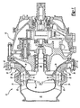
- Figure 1 is a partial cross-sectional view of a preferred embodiment of axial turbine starter;
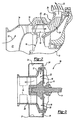
- Figure 2 is an enlarged view of the diffuser portion of the axial turbine starter shown in Figure 1;
- Figure 3 is a partial cross-sectional view of a preferred embodiment of radial turbine starter;
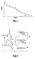
- Figure 4 is a torque versus speed graph for a particular turbine with and without the spoilers of the preferred embodiment; and
- Figure 5 is a schematic view of the rotor blades and spoiler of the preferred embodiment.
- A gas turbine
engine turbine starter 10 is shown in Figure 1. Thestarter 10 is often used to start gas turbines or other types of engines. Thestarter 10 includes ahousing 12 that supports aturbine 16. Theturbine 16 indudes a shaft 14havingblades 18 extending radially from theshaft 14.Starter housing 12, which may include several portions secured together, defines anintake 21 for channeling air toward therotor 16. - A starter having an axial turbine is shown in Figures 1 and 2. The
housing 12 further defines apassageway 22 having aninlet 24 and anoutlet 26. Therotor blades 18 are arranged between theinlet 24 andoutlet 26. Thepassageway 22 also includes adiffuser portion 28 generally extending from the area proximate to theblades 18 to theoutlet 26. In operation,fluid 32 flows from theintake 21 through theinlet 24 of thepassageway 22. A pressure differential across therotor 16 rotates therotor 16 andshaft 14.Fluid 32 exits therotor blades 18 and would flow uninterrupted through thediffuser portion 28 and out theoutlet 26 for prior art axial turbines. - A portion of a
starter 10 having aradial turbine 16 is shown in Figure 3. Similar to the axial turbine shown in Figure 2, thestarter 10 has ahousing 12 defining apassageway 22 having aninlet 24 and anoutlet 26. With radial turbines, theinlet 24 is arranged radially about thestarter 10 vine theoutlet 26 is centrally located. Therotor blades 18 are arranged between theinlet 24 andoutlet 26. In operation,fluid 32 flows from theintake 21 through theinlet 24 of thepassageway 22. Flow through therotor 16 rotates therotor 16 andshaft 14.Fluid 32 exits therotor blades 18 and would flow uninterrupted through theoutlet 26 for prior art axial turbines. - A graph of the torque versus speed characteristics for prior art turbine configurations is shown by the solid line in Figure 4. The torque versus speed relationship is generally linear, extending from a maximum torque-low speed condition shown at point A, to a maximum speed-no-load condition, shown by point C.
- With continuing reference to Figure 4, it is desirable to reduce the maximum speed at the no-load condition to reduce the potentially damaging stresses on the turbine. To this end, a plurality of
spoilers 34 are arranged radially within thepassageway 22 between therotor blades 18 and theoutlet 26. Preferably, thespoilers 34 are fixed to thepassageway 22. Referring to Figure 5, therotor blades 18 have aprofile 30 that affects the flow offluid 32 from therotor blades 18, which varies throughout the operating speeds of the turbine. Specifically, turbines may be designed such that at their peak efficiency points, the gas exiting therotor blades 18 leaves with near-zero or negligible swirl. That is, at the peak efficiency point the fluid 32 exiting therotor blades 18 generates a minimal amount of turbulence. Thefluids 32 often exits therotor blades 18 with an increased swirl, or turbulent flow, at speeds below and above the peak efficiency point. - The
spoilers 34 deflect the fluid 32 exiting theblades 18 and reduce the speed of the turbine to a desired rotor speed where the stresses on the turbine are of less concern. The torque versus speed curve for a turbine having thespoilers 34 of the preferred embodiment is shown by the dashed line in Figure 4. The peak efficiency, represented by point B, remains generally the same as with a turbine not having the spoilers of the preferred embodiment. In this manner, the peak efficiency may be maintained. However, above and below the efficiency point B, the fluid 32 exits therotor blades 18 with an increased swirl and collides with thespoilers 34 creating a back pressure in thediffuser portion 28 and slowing the speed of the turbine. As a result, the maximum speed at the no-load condition is reduced, as shown by point D. Said another way, the exiting flow impinges on the spoiler at the condition where speed reduction is required, and theflow 32 runs parallel to the surface of the spoiler at conditions where no reduction is required. However, it is to be understood that the spoilers may be positioned to accommodate normal exiting swirl, that is, as mentioned above, some swirl may exist at the peak efficiency point. This minimal swirl runs generally parallel to the spoiler at the peak efficiency point. Accordingly, the turbine is not permitted to reach high speeds at which the turbine may be highly stressed and potentially fail. - It is to be understood that the
spoilers 34 of the preferred embodiment need not be limited to reducing the speed at only the no-load condition. Thespoiler 34 may be designed to reduce the particular rate of any speed if desirable. Moreover, the number, angle, and other characteristics of thespoiler 34 may be modified to suit a particular turbine and turbine operating conditions. - The invention has been described in an illustrative manner, and it is to be understood that the terminology that has been used is intended to be in the nature of words of description rather than of limitation. Obviously, many modifications and variations of the present invention are possible in light of the above teachings. It is, therefore, to be understood that within the scope of the appended claims the invention may be practiced otherwise than as specifically described.
Claims (5)
- A turbine starter (10) comprising:a housing (12) defining a fluid passageway (22) with an inlet (24) and an outlet (26);a turbine rotor (16) with a blade (18) arranged in said passageway (22) between said inlet (24) and said outlet (26), said rotor (16) movable within said passageway (22) at a speed with a fluid exiting said blade (18) toward said outlet (26); anda plurality of spoilers (34) disposed in a radial pattern in said passageway (22) between said rotor (16) and said outlet (26);said plurality of spoilers (34) deflects said fluid exiting said blade (18) and produces a desired rotor speed (D) at a no-load condition which is less than a maximum rotor speed (C) at a no-load condition of the turbine starter (10) not having said spoilers (34); characterised in that a particular rotor speed (B) produces a peak efficiency, with said fluid exiting said blade (18) and through said plurality of spoilers (34) generally uninhibited as with the turbine starter (10) not having said spoilers (34) and producing a near-zero swirl at said particular rotor speed (B).
- The turbine starter (10) according to claim 1, wherein said plurality of spoilers (34) is fixed relative to said passageway (22).
- The turbine starter (10) according to claim 1, wherein said rotor (16) is an axial turbine rotor.
- The turbine starter (10) according to claim 1, wherein said rotor (16) is a radial turbine rotor.
- A method of limiting turbine speed comprising the steps of:a) rotating a rotor at a speed;b) expelling fluid from a rotor blade (18); andc) reducing the speed to a desired rotor speed (D)by d) deflecting the fluid with a plurality of spoilers (34) disposed in a radial pattern;the desired rotor speed (D) occuring at a no-load condition and being less than a maximum rotor speed (C) at a no-load condition of the turbine not having said spoilers (34); characterised in that a peak efficiency is produced at a particular rotor speed (B) with said fluid exiting said blade (18) and through said plurality of spoilers (34) generally uninhibited as with the turbine not having said spoilers (34) and producing a near-zero swirl at said particular rotor speed (B).
Applications Claiming Priority (3)
| Application Number | Priority Date | Filing Date | Title |
|---|---|---|---|
| US09/907,107 US6537027B2 (en) | 2001-07-17 | 2001-07-17 | Turbine no-load speed limiter |
| US907107 | 2001-07-17 | ||
| PCT/US2002/018932 WO2003098006A2 (en) | 2001-07-17 | 2002-06-13 | Turbine no-load speed limiter |
Publications (2)
| Publication Number | Publication Date |
|---|---|
| EP1427915A2 EP1427915A2 (en) | 2004-06-16 |
| EP1427915B1 true EP1427915B1 (en) | 2005-09-21 |
Family
ID=25423531
Family Applications (1)
| Application Number | Title | Priority Date | Filing Date |
|---|---|---|---|
| EP02807453A Expired - Lifetime EP1427915B1 (en) | 2001-07-17 | 2002-06-13 | Turbine no-load speed limiter |
Country Status (6)
| Country | Link |
|---|---|
| US (1) | US6537027B2 (en) |
| EP (1) | EP1427915B1 (en) |
| AT (1) | ATE305082T1 (en) |
| AU (1) | AU2002367892A1 (en) |
| DE (1) | DE60206292T2 (en) |
| WO (1) | WO2003098006A2 (en) |
Families Citing this family (11)
| Publication number | Priority date | Publication date | Assignee | Title |
|---|---|---|---|---|
| US20120006035A1 (en) * | 2010-07-07 | 2012-01-12 | Hamilton Sundstrand Corporation | Turbine rim cutter for air turbine starter |
| US8613142B2 (en) | 2010-07-30 | 2013-12-24 | Hamilton Sundstrand Corporation | Methods for cluster gear timing and manufacturing |
| US8876476B2 (en) | 2010-11-16 | 2014-11-04 | Hamilton Sundstrand Corporation | Integrated accessory gearbox and engine starter |
| WO2015154236A1 (en) * | 2014-04-09 | 2015-10-15 | GM Global Technology Operations LLC | Systems and methods for reinforced adhesive bonding |
| US20190032567A1 (en) * | 2017-07-26 | 2019-01-31 | Unison Industries, Llc | Air turbine starter |
| US11384691B2 (en) | 2020-03-06 | 2022-07-12 | Hamilton Sundstrand Corporation | Integrated exhaust baffle and split line retaining plate |
| US11753997B2 (en) * | 2020-03-26 | 2023-09-12 | Hamilton Sundstrand Corporation | Exhaust baffle component for an air turbine assembly |
| US12134987B2 (en) | 2020-03-26 | 2024-11-05 | Hamilton Sundstrand Corporation | Exhaust baffle component for an air turbine starter assembly |
| EP3885537A1 (en) * | 2020-03-26 | 2021-09-29 | Unison Industries LLC | Air turbine starter containment system and method of forming such a system |
| CN111611658B (en) * | 2020-05-22 | 2022-05-17 | 西北工业大学 | A kind of air turbine starter turbine blade and design method thereof |
| CN112576429B (en) * | 2021-01-13 | 2021-09-24 | 宁夏隆丰园林景观工程有限公司 | Underwater hydroelectric generation device with overspeed protection function |
Family Cites Families (8)
| Publication number | Priority date | Publication date | Assignee | Title |
|---|---|---|---|---|
| DE661671C (en) * | 1934-08-13 | 1938-06-24 | Der Maschinenfabrik Von Theodo | Device on water turbines to reduce undesired increases in speed |
| GB665916A (en) * | 1948-10-01 | 1952-02-06 | Plessey Co Ltd | A cordite operated starter turbine |
| US2951678A (en) * | 1954-05-04 | 1960-09-06 | Thompson Ramo Wooldridge Inc | Aerodynamic overspeed control for turbines |
| US3073114A (en) * | 1959-04-06 | 1963-01-15 | United Aircraft Corp | Vortex venturi |
| GB947690A (en) * | 1960-04-04 | 1964-01-29 | United Aircraft Corp | Turbine control |
| US3574476A (en) * | 1968-08-29 | 1971-04-13 | Garrett Corp | Control system for engine starters |
| DE2352285C2 (en) * | 1973-10-18 | 1975-03-06 | Aeg-Kanis Turbinenfabrik Gmbh, 8500 Nuernberg | Axial gas turbine |
| US4159624A (en) | 1978-02-06 | 1979-07-03 | Gruner George P | Contra-rotating rotors with differential gearing |
-
2001
- 2001-07-17 US US09/907,107 patent/US6537027B2/en not_active Expired - Lifetime
-
2002
- 2002-06-13 AT AT02807453T patent/ATE305082T1/en not_active IP Right Cessation
- 2002-06-13 EP EP02807453A patent/EP1427915B1/en not_active Expired - Lifetime
- 2002-06-13 WO PCT/US2002/018932 patent/WO2003098006A2/en not_active Ceased
- 2002-06-13 AU AU2002367892A patent/AU2002367892A1/en not_active Abandoned
- 2002-06-13 DE DE60206292T patent/DE60206292T2/en not_active Expired - Lifetime
Also Published As
| Publication number | Publication date |
|---|---|
| US6537027B2 (en) | 2003-03-25 |
| WO2003098006A3 (en) | 2004-03-04 |
| WO2003098006A2 (en) | 2003-11-27 |
| WO2003098006A8 (en) | 2004-04-29 |
| EP1427915A2 (en) | 2004-06-16 |
| DE60206292D1 (en) | 2006-02-02 |
| AU2002367892A8 (en) | 2003-12-02 |
| AU2002367892A1 (en) | 2003-12-02 |
| ATE305082T1 (en) | 2005-10-15 |
| US20030017045A1 (en) | 2003-01-23 |
| DE60206292T2 (en) | 2006-05-11 |
Similar Documents
| Publication | Publication Date | Title |
|---|---|---|
| EP1252424B1 (en) | Method of operating a variable cycle gas turbine engine | |
| EP0790390B1 (en) | Turbomachine rotor blade tip sealing | |
| EP2230382B1 (en) | Gas turbine rotor stage | |
| EP1790828B1 (en) | Dirt separator for compressor diffuser in gas turbine engine | |
| EP3043045B1 (en) | Turbocharger with adjustable-trim centrifugal compressor | |
| US7189059B2 (en) | Compressor including an enhanced vaned shroud | |
| EP2982833B1 (en) | Gas turbine engine | |
| US8122724B2 (en) | Compressor including an aerodynamically variable diffuser | |
| EP2333237B1 (en) | Multistage bladed tip fan | |
| KR101996685B1 (en) | Variable-pitch nozzle for a radial flow turbine, in particular for a turbine of an auxiliary power source | |
| US6183195B1 (en) | Single slot impeller bleed | |
| US6537027B2 (en) | Turbine no-load speed limiter | |
| JP4012507B2 (en) | Double flow compressor | |
| EP0083199A2 (en) | Surge control of a fluid compressor | |
| EP2946117B1 (en) | Variable area vane arrangement with lever arm and turbine engine therewith | |
| CA1086137A (en) | Jet flap controlled fuel pump | |
| CA2567940C (en) | Methods and apparatuses for gas turbine engines | |
| US6735952B2 (en) | Single pump lubrication and starter system | |
| EP0926332B1 (en) | Operating method for a jet engine | |
| RU2235908C2 (en) | Gas-turbine engine compressor |
Legal Events
| Date | Code | Title | Description |
|---|---|---|---|
| PUAI | Public reference made under article 153(3) epc to a published international application that has entered the european phase |
Free format text: ORIGINAL CODE: 0009012 |
|
| 17P | Request for examination filed |
Effective date: 20040213 |
|
| AK | Designated contracting states |
Kind code of ref document: A2 Designated state(s): AT BE CH CY DE DK ES FI FR GB GR IE IT LI LU MC NL PT SE TR |
|
| AX | Request for extension of the european patent |
Extension state: AL LT LV MK RO SI |
|
| 17Q | First examination report despatched |
Effective date: 20040809 |
|
| GRAP | Despatch of communication of intention to grant a patent |
Free format text: ORIGINAL CODE: EPIDOSNIGR1 |
|
| RIC1 | Information provided on ipc code assigned before grant |
Ipc: 7F 03B 15/18 B Ipc: 7F 02C 9/20 B Ipc: 7F 02C 7/277 B Ipc: 7F 01D 9/02 B Ipc: 7F 01D 1/00 A |
|
| GRAS | Grant fee paid |
Free format text: ORIGINAL CODE: EPIDOSNIGR3 |
|
| GRAA | (expected) grant |
Free format text: ORIGINAL CODE: 0009210 |
|
| AK | Designated contracting states |
Kind code of ref document: B1 Designated state(s): AT BE CH CY DE DK ES FI FR GB GR IE IT LI LU MC NL PT SE TR |
|
| PG25 | Lapsed in a contracting state [announced via postgrant information from national office to epo] |
Ref country code: IT Free format text: LAPSE BECAUSE OF FAILURE TO SUBMIT A TRANSLATION OF THE DESCRIPTION OR TO PAY THE FEE WITHIN THE PRESCRIBED TIME-LIMIT;WARNING: LAPSES OF ITALIAN PATENTS WITH EFFECTIVE DATE BEFORE 2007 MAY HAVE OCCURRED AT ANY TIME BEFORE 2007. THE CORRECT EFFECTIVE DATE MAY BE DIFFERENT FROM THE ONE RECORDED. Effective date: 20050921 Ref country code: BE Free format text: LAPSE BECAUSE OF FAILURE TO SUBMIT A TRANSLATION OF THE DESCRIPTION OR TO PAY THE FEE WITHIN THE PRESCRIBED TIME-LIMIT Effective date: 20050921 Ref country code: CH Free format text: LAPSE BECAUSE OF FAILURE TO SUBMIT A TRANSLATION OF THE DESCRIPTION OR TO PAY THE FEE WITHIN THE PRESCRIBED TIME-LIMIT Effective date: 20050921 Ref country code: AT Free format text: LAPSE BECAUSE OF FAILURE TO SUBMIT A TRANSLATION OF THE DESCRIPTION OR TO PAY THE FEE WITHIN THE PRESCRIBED TIME-LIMIT Effective date: 20050921 Ref country code: LI Free format text: LAPSE BECAUSE OF FAILURE TO SUBMIT A TRANSLATION OF THE DESCRIPTION OR TO PAY THE FEE WITHIN THE PRESCRIBED TIME-LIMIT Effective date: 20050921 Ref country code: NL Free format text: LAPSE BECAUSE OF FAILURE TO SUBMIT A TRANSLATION OF THE DESCRIPTION OR TO PAY THE FEE WITHIN THE PRESCRIBED TIME-LIMIT Effective date: 20050921 Ref country code: FI Free format text: LAPSE BECAUSE OF FAILURE TO SUBMIT A TRANSLATION OF THE DESCRIPTION OR TO PAY THE FEE WITHIN THE PRESCRIBED TIME-LIMIT Effective date: 20050921 |
|
| REG | Reference to a national code |
Ref country code: GB Ref legal event code: FG4D |
|
| REG | Reference to a national code |
Ref country code: CH Ref legal event code: EP |
|
| REG | Reference to a national code |
Ref country code: IE Ref legal event code: FG4D |
|
| REF | Corresponds to: |
Ref document number: 60206292 Country of ref document: DE Date of ref document: 20051027 Kind code of ref document: P |
|
| PG25 | Lapsed in a contracting state [announced via postgrant information from national office to epo] |
Ref country code: SE Free format text: LAPSE BECAUSE OF FAILURE TO SUBMIT A TRANSLATION OF THE DESCRIPTION OR TO PAY THE FEE WITHIN THE PRESCRIBED TIME-LIMIT Effective date: 20051221 Ref country code: GR Free format text: LAPSE BECAUSE OF FAILURE TO SUBMIT A TRANSLATION OF THE DESCRIPTION OR TO PAY THE FEE WITHIN THE PRESCRIBED TIME-LIMIT Effective date: 20051221 Ref country code: DK Free format text: LAPSE BECAUSE OF FAILURE TO SUBMIT A TRANSLATION OF THE DESCRIPTION OR TO PAY THE FEE WITHIN THE PRESCRIBED TIME-LIMIT Effective date: 20051221 |
|
| PG25 | Lapsed in a contracting state [announced via postgrant information from national office to epo] |
Ref country code: ES Free format text: LAPSE BECAUSE OF FAILURE TO SUBMIT A TRANSLATION OF THE DESCRIPTION OR TO PAY THE FEE WITHIN THE PRESCRIBED TIME-LIMIT Effective date: 20060101 |
|
| REF | Corresponds to: |
Ref document number: 60206292 Country of ref document: DE Date of ref document: 20060202 Kind code of ref document: P |
|
| PG25 | Lapsed in a contracting state [announced via postgrant information from national office to epo] |
Ref country code: PT Free format text: LAPSE BECAUSE OF FAILURE TO SUBMIT A TRANSLATION OF THE DESCRIPTION OR TO PAY THE FEE WITHIN THE PRESCRIBED TIME-LIMIT Effective date: 20060221 |
|
| NLV1 | Nl: lapsed or annulled due to failure to fulfill the requirements of art. 29p and 29m of the patents act | ||
| REG | Reference to a national code |
Ref country code: CH Ref legal event code: PL |
|
| ET | Fr: translation filed | ||
| PG25 | Lapsed in a contracting state [announced via postgrant information from national office to epo] |
Ref country code: IE Free format text: LAPSE BECAUSE OF NON-PAYMENT OF DUE FEES Effective date: 20060613 |
|
| PG25 | Lapsed in a contracting state [announced via postgrant information from national office to epo] |
Ref country code: MC Free format text: LAPSE BECAUSE OF NON-PAYMENT OF DUE FEES Effective date: 20060630 |
|
| PLBE | No opposition filed within time limit |
Free format text: ORIGINAL CODE: 0009261 |
|
| STAA | Information on the status of an ep patent application or granted ep patent |
Free format text: STATUS: NO OPPOSITION FILED WITHIN TIME LIMIT |
|
| 26N | No opposition filed |
Effective date: 20060622 |
|
| REG | Reference to a national code |
Ref country code: IE Ref legal event code: MM4A |
|
| PG25 | Lapsed in a contracting state [announced via postgrant information from national office to epo] |
Ref country code: TR Free format text: LAPSE BECAUSE OF FAILURE TO SUBMIT A TRANSLATION OF THE DESCRIPTION OR TO PAY THE FEE WITHIN THE PRESCRIBED TIME-LIMIT Effective date: 20050921 Ref country code: LU Free format text: LAPSE BECAUSE OF NON-PAYMENT OF DUE FEES Effective date: 20060613 |
|
| PG25 | Lapsed in a contracting state [announced via postgrant information from national office to epo] |
Ref country code: CY Free format text: LAPSE BECAUSE OF FAILURE TO SUBMIT A TRANSLATION OF THE DESCRIPTION OR TO PAY THE FEE WITHIN THE PRESCRIBED TIME-LIMIT Effective date: 20050921 |
|
| PGFP | Annual fee paid to national office [announced via postgrant information from national office to epo] |
Ref country code: DE Payment date: 20130619 Year of fee payment: 12 |
|
| PGFP | Annual fee paid to national office [announced via postgrant information from national office to epo] |
Ref country code: FR Payment date: 20130719 Year of fee payment: 12 |
|
| REG | Reference to a national code |
Ref country code: DE Ref legal event code: R119 Ref document number: 60206292 Country of ref document: DE |
|
| REG | Reference to a national code |
Ref country code: FR Ref legal event code: ST Effective date: 20150227 |
|
| PG25 | Lapsed in a contracting state [announced via postgrant information from national office to epo] |
Ref country code: DE Free format text: LAPSE BECAUSE OF NON-PAYMENT OF DUE FEES Effective date: 20150101 |
|
| REG | Reference to a national code |
Ref country code: DE Ref legal event code: R119 Ref document number: 60206292 Country of ref document: DE Effective date: 20150101 |
|
| PG25 | Lapsed in a contracting state [announced via postgrant information from national office to epo] |
Ref country code: FR Free format text: LAPSE BECAUSE OF NON-PAYMENT OF DUE FEES Effective date: 20140630 |
|
| PGFP | Annual fee paid to national office [announced via postgrant information from national office to epo] |
Ref country code: GB Payment date: 20190522 Year of fee payment: 18 |
|
| GBPC | Gb: european patent ceased through non-payment of renewal fee |
Effective date: 20200613 |
|
| PG25 | Lapsed in a contracting state [announced via postgrant information from national office to epo] |
Ref country code: GB Free format text: LAPSE BECAUSE OF NON-PAYMENT OF DUE FEES Effective date: 20200613 |