EP1427248A2 - Speaker device - Google Patents
Speaker device Download PDFInfo
- Publication number
- EP1427248A2 EP1427248A2 EP03257238A EP03257238A EP1427248A2 EP 1427248 A2 EP1427248 A2 EP 1427248A2 EP 03257238 A EP03257238 A EP 03257238A EP 03257238 A EP03257238 A EP 03257238A EP 1427248 A2 EP1427248 A2 EP 1427248A2
- Authority
- EP
- European Patent Office
- Prior art keywords
- damper
- speaker device
- voice coil
- damper holder
- housing
- Prior art date
- Legal status (The legal status is an assumption and is not a legal conclusion. Google has not performed a legal analysis and makes no representation as to the accuracy of the status listed.)
- Granted
Links
Images


Classifications
-
- H—ELECTRICITY
- H04—ELECTRIC COMMUNICATION TECHNIQUE
- H04R—LOUDSPEAKERS, MICROPHONES, GRAMOPHONE PICK-UPS OR LIKE ACOUSTIC ELECTROMECHANICAL TRANSDUCERS; ELECTRIC HEARING AIDS; PUBLIC ADDRESS SYSTEMS
- H04R9/00—Transducers of moving-coil, moving-strip, or moving-wire type
- H04R9/02—Details
- H04R9/04—Construction, mounting, or centering of coil
- H04R9/041—Centering
- H04R9/043—Inner suspension or damper, e.g. spider
-
- H—ELECTRICITY
- H04—ELECTRIC COMMUNICATION TECHNIQUE
- H04R—LOUDSPEAKERS, MICROPHONES, GRAMOPHONE PICK-UPS OR LIKE ACOUSTIC ELECTROMECHANICAL TRANSDUCERS; ELECTRIC HEARING AIDS; PUBLIC ADDRESS SYSTEMS
- H04R31/00—Apparatus or processes specially adapted for the manufacture of transducers or diaphragms therefor
- H04R31/006—Interconnection of transducer parts
Definitions
- the present invention relates to a speaker device.
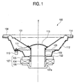
- Fig. 1 shows an example of a speaker device which is recently often used as a home device or an in-vehicle device.
- the speaker device 100 is driven by the moving coil system.
- An annular magnet 104 is placed on a pole yoke 106, and an annular plate 105 is placed on the annular magnet 104.
- the pole yoke 106, the annular magnet 104, and the annular plate 105 form a magnetic circuit 107.
- a voice coil 102 which is wound around an end portion of a voice coil bobbin 103 is placed in a magnetic gap 107a of the magnetic circuit 107.
- the voice coil bobbin 103 is fixed to a center hole of a cone paper 101 which is a substantially conical diaphragm.
- a cap 113 is attached to the center hole.
- An edge 108 is disposed in an outer peripheral portion of the cone paper 101, and attached to an outer peripheral edge of a frame 112 via a paper gasket 114.
- a center portion of the cone paper 101 is supported by the frame 112 via a damper 109, so that the cone paper 101, the voice coil 102, and the voice coil bobbin 103 are vibrating available in an integrated state in the direction of the center axis X of the speaker device 100.
- Positive and negative input terminals 110 are attached to the frame 112.
- the ends of the voice coil 102 are electrically connected to the positive and negative input terminals 110 via lead wires (tinsel wires) 111, respectively.
- a driving signal (driving current) is supplied from an external power source to the input terminals 110.
- the voice coil 102 receives an electromagnetic driving force corresponding to the driving signal.
- the voice coil 102 is vibrated in the direction of the center axis X of the speaker device 100, integrally with the voice coil bobbin 103 and the cone paper 101, so that an acoustic energy corresponding to the driving signal is radiated from the cone paper 101.
- an exciting coil which functions as an electromagnet may be used in place of the magnet 104 to form the magnetic circuit.
- the outer peripheral edge of the damper 109 is bonded to the frame 112. Therefore, resonance of the damper 109 and the frame 112 are transmitted through the damper 109 to be returned to the voice coil 102, thereby causing a problem in that a sound which is delayed and distorted is transmitted to the cone paper 101 to impair the sound quality.
- the present invention has been made to solve the above problems, and therefore an object of the invention is to transmit resonance of the damper and the frame through the damper to be returned to the voice coil, thereby impairing the sound quality.
- a speaker device comprising: a magnetic circuit including a magnet and a yoke; a voice coil which is placed in a magnetic gap of the magnetic circuit; a diaphragm which is vibrating available in a state where the diaphragm is coupled with the voice coil; and a damper which is placed between a portion of the diaphragm on a side of the voice coil and a housing, wherein the speaker device has a damper holder which is disposed on the housing, and to which the damper is connected, and the housing and the damper holder are in contact with each other via projections which are disposed on one of the housing and the damper holder.
- Fig. 2 is a section view of the speaker device of the invention
- Fig. 3 is a front view of the speaker device
- Fig. 4 is a rear view of the speaker device.
- the speaker device 10 has a yoke 11 in a center portion, and an annular magnet 14 and an annular plate 15 are outside the yoke 11. These components constitute a magnetic circuit 13 while forming a magnetic gap 12 between the plate and the yoke 11.
- the magnet 14 may be excited by a DC power source, or alternatively may be configured by using a permanent magnet.
- a voice coil 16 which is formed by a thin copper wire is disposed in the magnetic gap 12 so as to be movable backward and forward.
- the voice coil 16 is attached to a center hole of a cone paper 17 which is a substantially conical diaphragm.
- a cap 18 is attached in front of the center hole of the cone paper 17.
- a circular attachment face 21 which constitutes a frame 20 serving as a housing is attached to the rear face of the yoke 11 by screws 22.
- Plural (in the embodiment, five) arms 23 are disposed so as to forward extend from the attachment face 21 in a radial manner to surround the yoke 11 and the magnet 14.
- a terminal support ring 24 is attached to intermediate positions of the arms 23.
- a pair of positive and negative speaker terminals 25a, 25b are attached to a lower portion of the terminal support ring 24.
- the voice coil 16 is electrically connected to the positive and negative speaker terminals 25a, 25b via lead wires (tinsel wires) 26.
- a damper 27 is disposed between the terminal support ring 24 and the cone paper 17 to support the voice coil 16 at a correct position in the magnetic gap 12.
- the damper 27 is provided with flexibility so that the damper can flexibly follow to-and-fro movement of the voice coil 16.
- a ring portion 28 is disposed integrally on the tip ends of the arms 23. An outer peripheral edge 17a of the cone paper 17 is attached to the ring portion 28.
- edges 17b are concentrically formed in the vicinity of the outer peripheral edge of the cone paper 17.
- the edges 17b are bent into a generally arcuate shape so that the cone paper 17 can smoothly vibrate and abnormal motion during vibration can be suppressed.
- the voice coil 16 When a signal current flows into the voice coil 16 from the speaker terminals 25a, 25b connected to an external power source, therefore, the voice coil 16 generates a magnetic field which cooperates with the magnetic circuit 13, thereby causing the voice coil 16 to vibrate backward and forward. As a result, the cone paper 17 vibrates backward and forward to generate a sound in the form of a compressive wave of air.
- Fig. 5 is an enlarged section view showing a portion where the damper 27 is attached to the frame 20.
- the damper 27 is attached to the frame 20 via a damper holder 30.
- the frame 20 and the damper holder 30 are in contact with each other via projections 31 which are disposed on one of the frame 20 and the damper holder 30. Therefore, the projections 31 may be disposed on the damper holder 30, or alternatively on the frame 20.
- the projections 31 are formed. In this case, preferably, the projections 31 are arranged at regular intervals (for example, at a center angle of 120 degrees).
- the projections 31 has a shape which can support a counter member at points, such as a conical shape 31a shown in Fig. 6A, or a spherical shape 31b shown in Fig. 6B.
- the damper holder 30 is made of a hybrid material of a resin and tungsten. Preferably, polypropylene is used as the resin.
- the damper holder 30 is set to have a specific gravity of 10.0 or larger.
- the projections 31 are disposed on one of the damper holder 30 and the frame 20, so that the damper holder 30 and the frame 20 make point contact with each other. Therefore, propagations of resonance in the damper 27 and the frame 20 are coupled to each other through points. In the bass range, therefore, the damper holder 30 and the frame 20 are caused by the point coupling to operate in phase, and hence attenuation does not occur. By contrast, in the midrange, they operate in anti-phase, so that unwanted resonance can be attenuated.
- the speaker device 10 can be increased in weight while maintaining the volume, and the reaction component of the magnetic circuit can be reduced.
- the damper holder 30 is made of a metal alloy, the specific gravity is 9 or smaller, and the attenuation factor is low. Therefore, it can be said that the hybrid material in the invention is superior in performance.
- damper holder 30 In order to enhance the rigidity of the damper holder 30, an aluminum die-casting is usually used. Such a damper holder 30 has an advantage that the thickness can be increased while reducing the weight. However, large resonance peculiar to the material occurs.
- the damper holder 30 which supports the vibration system is requested to have a larger attenuation amount and a higher specific gravity. It is an object to obtain a higher specific gravity than that of an alloy while attaining the same attenuation amount as that in the case of an alloy.
- the use of pure tungsten has been studied, attention has been focused on a resin and tungsten, and various material compounds have been studied, with the result that a material which can accomplish the object is obtained.
- the speaker device 10 of the invention is not restricted to the above-described embodiment, and may be adequately subjected to modification, improvement, or the like.
- a speaker device of the cone type has been described.
- the invention may be similarly applied to a speaker device of the dome type.
Landscapes
- Physics & Mathematics (AREA)
- Engineering & Computer Science (AREA)
- Acoustics & Sound (AREA)
- Signal Processing (AREA)
- Audible-Bandwidth Dynamoelectric Transducers Other Than Pickups (AREA)
- Diaphragms For Electromechanical Transducers (AREA)
Abstract
Description
Claims (5)
- A speaker device comprising:wherein said speaker device has a damper holder which is disposed on said housing, and to which said damper is connected, and said housing and said damper holder are in contact with each other via projections which are disposed on one of said housing and said damper holder.a magnetic circuit including a magnet and a yoke;a voice coil which is placed in a magnetic gap of said magnetic circuit;a diaphragm which is vibrating available in a state where said diaphragm is coupled with said voice coil; anda damper which is placed between a portion of said diaphragm on a side of said voice coil and a housing,
- A speaker device according to claim 1, wherein said projections are three or more in number.
- A speaker device according to claim 1, wherein said damper holder is made of a hybrid material of a resin and tungsten.
- A speaker device according to claim 3, wherein said resin is polypropylene.
- A speaker device according to claim 3, wherein said damper holder has a specific gravity of 10.0 or larger.
Applications Claiming Priority (2)
| Application Number | Priority Date | Filing Date | Title |
|---|---|---|---|
| JP2002355182 | 2002-12-06 | ||
| JP2002355182A JP3861123B2 (en) | 2002-12-06 | 2002-12-06 | Speaker device |
Publications (3)
| Publication Number | Publication Date |
|---|---|
| EP1427248A2 true EP1427248A2 (en) | 2004-06-09 |
| EP1427248A3 EP1427248A3 (en) | 2005-07-06 |
| EP1427248B1 EP1427248B1 (en) | 2009-12-23 |
Family
ID=32310762
Family Applications (1)
| Application Number | Title | Priority Date | Filing Date |
|---|---|---|---|
| EP03257238A Expired - Lifetime EP1427248B1 (en) | 2002-12-06 | 2003-11-17 | Speaker device |
Country Status (5)
| Country | Link |
|---|---|
| US (1) | US7010141B2 (en) |
| EP (1) | EP1427248B1 (en) |
| JP (1) | JP3861123B2 (en) |
| CN (1) | CN1310572C (en) |
| DE (1) | DE60330645D1 (en) |
Families Citing this family (8)
| Publication number | Priority date | Publication date | Assignee | Title |
|---|---|---|---|---|
| JP2005341294A (en) * | 2004-05-27 | 2005-12-08 | Pioneer Electronic Corp | Speaker apparatus, and its manufacturing method |
| JP4079134B2 (en) | 2004-09-03 | 2008-04-23 | ソニー株式会社 | Data receiver |
| JP4400439B2 (en) * | 2004-12-14 | 2010-01-20 | パナソニック株式会社 | Speaker |
| KR100661921B1 (en) | 2005-04-15 | 2006-12-27 | 삼성전기주식회사 | Vibration and sound generators and yokes used therein |
| JP2007088911A (en) * | 2005-09-22 | 2007-04-05 | Pioneer Electronic Corp | Speaker device |
| JP4717666B2 (en) * | 2006-03-09 | 2011-07-06 | パイオニア株式会社 | Connected body of speaker device |
| CN101754075A (en) * | 2008-12-11 | 2010-06-23 | 淇誉电子科技股份有限公司 | Improved structure of loudspeaker |
| US9729972B2 (en) * | 2013-04-01 | 2017-08-08 | Pioneer Corporation | Speaker device |
Family Cites Families (10)
| Publication number | Priority date | Publication date | Assignee | Title |
|---|---|---|---|---|
| GB375010A (en) * | 1931-04-16 | 1932-06-23 | Harry Claude Willson | Improvements relating to sound reproducing instruments |
| US1957562A (en) * | 1932-06-11 | 1934-05-08 | Magnavox Co | Diaphragm mounting |
| GB495999A (en) * | 1937-11-09 | 1938-11-23 | Harry Claude Willson | Improvements relating to electro-dynamic sound reproducers |
| US4531025A (en) * | 1984-03-19 | 1985-07-23 | Intersonics Incorporated | Loudspeaker with commutated coil drive |
| CN1067615A (en) * | 1991-06-14 | 1993-01-06 | 符方照 | False proof bill |
| CN2135889Y (en) * | 1992-09-07 | 1993-06-09 | 蔡明贵 | Improved loudspeaker structure |
| AU8491398A (en) * | 1997-07-18 | 1999-02-10 | Mackie Designs Inc. | Pistonic motion, large excursion passive radiator |
| US6385327B1 (en) * | 1998-06-16 | 2002-05-07 | U.S. Philips Corporation | Device having two coaxially disposed bodies which are movable relative to one another along a translation axis |
| US6173065B1 (en) * | 1999-08-03 | 2001-01-09 | Steff Lin | Structure of speaker |
| WO2002085064A2 (en) * | 2001-04-17 | 2002-10-24 | Sahyoun Joseph Y | Acoustic radiator with a baffle of a diameter at least as large as the opening of the speaker enclosure to which it is mounted |
-
2002
- 2002-12-06 JP JP2002355182A patent/JP3861123B2/en not_active Expired - Fee Related
-
2003
- 2003-11-17 EP EP03257238A patent/EP1427248B1/en not_active Expired - Lifetime
- 2003-11-17 DE DE60330645T patent/DE60330645D1/en not_active Expired - Lifetime
- 2003-11-21 US US10/717,642 patent/US7010141B2/en not_active Expired - Lifetime
- 2003-12-08 CN CNB2003101201391A patent/CN1310572C/en not_active Expired - Fee Related
Also Published As
| Publication number | Publication date |
|---|---|
| DE60330645D1 (en) | 2010-02-04 |
| US20040109582A1 (en) | 2004-06-10 |
| JP3861123B2 (en) | 2006-12-20 |
| CN1310572C (en) | 2007-04-11 |
| EP1427248A3 (en) | 2005-07-06 |
| JP2004187232A (en) | 2004-07-02 |
| CN1507302A (en) | 2004-06-23 |
| US7010141B2 (en) | 2006-03-07 |
| EP1427248B1 (en) | 2009-12-23 |
Similar Documents
| Publication | Publication Date | Title |
|---|---|---|
| US8620017B2 (en) | Speaker and magnetic circuit | |
| JP2004147077A (en) | Composite speaker | |
| US7010141B2 (en) | Speaker device | |
| JP4173382B2 (en) | Coaxial type composite speaker | |
| JP4573591B2 (en) | Speaker unit, manufacturing method thereof, and speaker device | |
| JP3877209B2 (en) | Speaker device | |
| EP1113705A2 (en) | Diaphragm for speaker and speaker device provided with the same | |
| KR19990041872A (en) | Speaker structure with double voice coil | |
| JP2000152381A (en) | Speaker and speaker device | |
| JP3510094B2 (en) | Speaker device | |
| JP4699878B2 (en) | Speaker | |
| US8009858B2 (en) | Loudspeaker | |
| JP2004248007A (en) | Speaker system | |
| JP3208310B2 (en) | Electroacoustic transducer | |
| JP4020773B2 (en) | Speaker device | |
| JP2001169386A (en) | Radiating diaphragm and high frequency transducer | |
| JP2000165989A (en) | Speaker and speaker device | |
| JPH1141696A (en) | Speaker device | |
| JP2000188798A (en) | Speaker and speaker device | |
| JP2000023285A (en) | Speaker and speaker device | |
| US20060093182A1 (en) | Speaker | |
| JPH11215585A (en) | Speaker device | |
| JP2004187235A (en) | Speaker unit | |
| CN116782099A (en) | Loudspeaker | |
| JP2008167238A (en) | Speaker apparatus |
Legal Events
| Date | Code | Title | Description |
|---|---|---|---|
| PUAI | Public reference made under article 153(3) epc to a published international application that has entered the european phase |
Free format text: ORIGINAL CODE: 0009012 |
|
| AK | Designated contracting states |
Kind code of ref document: A2 Designated state(s): AT BE BG CH CY CZ DE DK EE ES FI FR GB GR HU IE IT LI LU MC NL PT RO SE SI SK TR |
|
| AX | Request for extension of the european patent |
Extension state: AL LT LV MK |
|
| PUAL | Search report despatched |
Free format text: ORIGINAL CODE: 0009013 |
|
| AK | Designated contracting states |
Kind code of ref document: A3 Designated state(s): AT BE BG CH CY CZ DE DK EE ES FI FR GB GR HU IE IT LI LU MC NL PT RO SE SI SK TR |
|
| AX | Request for extension of the european patent |
Extension state: AL LT LV MK |
|
| 17P | Request for examination filed |
Effective date: 20051220 |
|
| AKX | Designation fees paid |
Designated state(s): DE FR GB |
|
| 17Q | First examination report despatched |
Effective date: 20070726 |
|
| GRAP | Despatch of communication of intention to grant a patent |
Free format text: ORIGINAL CODE: EPIDOSNIGR1 |
|
| GRAS | Grant fee paid |
Free format text: ORIGINAL CODE: EPIDOSNIGR3 |
|
| GRAA | (expected) grant |
Free format text: ORIGINAL CODE: 0009210 |
|
| AK | Designated contracting states |
Kind code of ref document: B1 Designated state(s): DE FR GB |
|
| REG | Reference to a national code |
Ref country code: GB Ref legal event code: FG4D |
|
| REF | Corresponds to: |
Ref document number: 60330645 Country of ref document: DE Date of ref document: 20100204 Kind code of ref document: P |
|
| PLBE | No opposition filed within time limit |
Free format text: ORIGINAL CODE: 0009261 |
|
| STAA | Information on the status of an ep patent application or granted ep patent |
Free format text: STATUS: NO OPPOSITION FILED WITHIN TIME LIMIT |
|
| 26N | No opposition filed |
Effective date: 20100924 |
|
| REG | Reference to a national code |
Ref country code: FR Ref legal event code: PLFP Year of fee payment: 13 |
|
| REG | Reference to a national code |
Ref country code: FR Ref legal event code: PLFP Year of fee payment: 14 |
|
| REG | Reference to a national code |
Ref country code: FR Ref legal event code: PLFP Year of fee payment: 15 |
|
| REG | Reference to a national code |
Ref country code: FR Ref legal event code: PLFP Year of fee payment: 16 |
|
| PGFP | Annual fee paid to national office [announced via postgrant information from national office to epo] |
Ref country code: DE Payment date: 20191105 Year of fee payment: 17 |
|
| PGFP | Annual fee paid to national office [announced via postgrant information from national office to epo] |
Ref country code: FR Payment date: 20191015 Year of fee payment: 17 |
|
| PGFP | Annual fee paid to national office [announced via postgrant information from national office to epo] |
Ref country code: GB Payment date: 20191115 Year of fee payment: 17 |
|
| REG | Reference to a national code |
Ref country code: DE Ref legal event code: R119 Ref document number: 60330645 Country of ref document: DE |
|
| GBPC | Gb: european patent ceased through non-payment of renewal fee |
Effective date: 20201117 |
|
| PG25 | Lapsed in a contracting state [announced via postgrant information from national office to epo] |
Ref country code: FR Free format text: LAPSE BECAUSE OF NON-PAYMENT OF DUE FEES Effective date: 20201130 |
|
| PG25 | Lapsed in a contracting state [announced via postgrant information from national office to epo] |
Ref country code: DE Free format text: LAPSE BECAUSE OF NON-PAYMENT OF DUE FEES Effective date: 20210601 Ref country code: GB Free format text: LAPSE BECAUSE OF NON-PAYMENT OF DUE FEES Effective date: 20201117 |