EP1427246A1 - DIAGNOSIS SYSTEM, DIAGNOSIS METHOD, DIAGNOSIS TERMINAL, AND DIAGNOSIS TERMINAL USING METHOD - Google Patents
DIAGNOSIS SYSTEM, DIAGNOSIS METHOD, DIAGNOSIS TERMINAL, AND DIAGNOSIS TERMINAL USING METHOD Download PDFInfo
- Publication number
- EP1427246A1 EP1427246A1 EP02765343A EP02765343A EP1427246A1 EP 1427246 A1 EP1427246 A1 EP 1427246A1 EP 02765343 A EP02765343 A EP 02765343A EP 02765343 A EP02765343 A EP 02765343A EP 1427246 A1 EP1427246 A1 EP 1427246A1
- Authority
- EP
- European Patent Office
- Prior art keywords
- diagnosis
- object equipment
- terminal
- program
- database
- Prior art date
- Legal status (The legal status is an assumption and is not a legal conclusion. Google has not performed a legal analysis and makes no representation as to the accuracy of the status listed.)
- Withdrawn
Links
Images


Classifications
-
- G—PHYSICS
- G06—COMPUTING OR CALCULATING; COUNTING
- G06N—COMPUTING ARRANGEMENTS BASED ON SPECIFIC COMPUTATIONAL MODELS
- G06N5/00—Computing arrangements using knowledge-based models
- G06N5/02—Knowledge representation; Symbolic representation
- G06N5/022—Knowledge engineering; Knowledge acquisition
-
- G—PHYSICS
- G08—SIGNALLING
- G08C—TRANSMISSION SYSTEMS FOR MEASURED VALUES, CONTROL OR SIMILAR SIGNALS
- G08C25/00—Arrangements for preventing or correcting errors; Monitoring arrangements
- G08C25/02—Arrangements for preventing or correcting errors; Monitoring arrangements by signalling back receiving station to transmitting station
-
- H—ELECTRICITY
- H04—ELECTRIC COMMUNICATION TECHNIQUE
- H04Q—SELECTING
- H04Q9/00—Arrangements in telecontrol or telemetry systems for selectively calling a substation from a main station, in which substation desired apparatus is selected for applying a control signal thereto or for obtaining measured values therefrom
- H04Q9/04—Arrangements for synchronous operation
Definitions
- the present invention relates to a technique of diagnosing an object to be diagnosed.
- diagnosis in order to diagnose an air conditioner, there is a technique of monitoring the operation apart from the air conditioner or, further, diagnosing the air conditioner. According to the technique, a diagnosis program used in diagnosis does not have to be stored in the air conditioner itself. Therefore, diagnosis can be carried out without adding a function to the air conditioner, so that the cost of the air conditioner itself can be reduced.
- a device for carrying out diagnosis naturally has to have a diagnosis program.
- a diagnosis program a number of models exists for the air conditioners and parts to be diagnosed are various. For example, different diagnosis programs are used to diagnose faults for the case where a compressor in an air conditioner fails and the case where an electric expansion valve fails.
- An object of the present invention is to provide a technique of reducing the number of diagnosis programs to be stored in a device for carrying out diagnosis, improving portability of the device, and reducing the cost of the device.
- a first aspect of a diagnosis system comprises: a diagnosis object equipment (1), as an object of diagnosis, capable of transmitting diagnosis information (42) as information regarding the diagnosis of the diagnosis object equipment itself; a diagnosis database (4), which is separate from the diagnosis object equipment, for storing a plurality of diagnosis programs (51) used in carrying out the diagnosis on the diagnosis object equipment; and a diagnosis terminal (2), which is separate each from the diagnosis object equipment and the diagnosis database, for obtaining the diagnosis program from the diagnosis database on the basis of the diagnosis information, and carries out the diagnosis by using the diagnosis program.
- the diagnosis program (51) tests operation of the diagnosis part.
- a first aspect of a diagnosis method comprises steps of: (a) transmitting diagnosis information (42) as information regarding diagnosis on a diagnosis object equipment (1) as an object of diagnosis from the diagnosis object equipment to a diagnosis terminal (2) which is separate from the diagnosis object equipment (S2); (b) sending a request for transmission of a diagnosis program (51) used in carrying out the diagnosis from the diagnosis terminal to a diagnosis database (4) which is separate from each of the diagnosis object equipment and the diagnosis terminal (S3); (c) transmitting the diagnosis program corresponding to the diagnosis information from the diagnosis database to the diagnosis terminal (S4); and (d) carrying out the diagnosis by the diagnosis terminal by using the diagnosis program obtained in the step (c) (S5,S6).
- the diagnosis information (42) includes information of identifying a model of the diagnosis object equipment (1), and the diagnosis program (51) transmitted from the diagnosis database (4) to the diagnosis terminal (2) corresponds to the model of the diagnosis object equipment.
- the diagnosis information (42) includes information of identifying a diagnosis part in the diagnosis object equipment (1), and the diagnosis program (51) transmitted from the diagnosis database (4) to the diagnosis terminal (2) corresponds to the diagnosis part in the diagnosis object equipment.
- the diagnosis program (51) tests operation of the diagnosis part.
- the diagnosis object equipment (1) transmits a status signal (53) indicative of the status of itself to the diagnosis terminal in response to a request from the diagnosis program (51).
- the diagnosis terminal receives diagnosis information (42) as information regarding diagnosis on a diagnosis object equipment (1) from the diagnosis object equipment, receives a diagnosis program obtained on the basis of the diagnosis information from a diagnosis database (4) which is separate from said diagnosis object equipment and stores a plurality of the diagnosis programs, and carries out the diagnosis on the diagnosis object equipment by using the diagnosis program.
- the diagnosis terminal is separate from the diagnosis object equipment and the diagnosis database.
- the diagnosis object equipment (1) transmits a status signal (53) indicative of the status of itself to the diagnosis terminal (2) in response to a request from the diagnosis program (51).
- the diagnosis information (42) includes information of identifying a model of the diagnosis object equipment (1), and the diagnosis program (51) received from the diagnosis database (4) corresponds to the model of the diagnosis object equipment.
- the diagnosis program (51) tests operation of the diagnosis part.
- the diagnosis object equipment (1) transmits a status signal (53) indicative of the status of itself to the diagnosis terminal in response to a request from the diagnosis program (51).
- diagnosis object equipment since the diagnosis object equipment is provided separately from the diagnosis database, it is unnecessary to provide the diagnosis object equipment with the function of carrying out diagnosis. Therefore, the cost of the diagnosis object equipment can be reduced. Since the diagnosis terminal is separate from the diagnosis database, the diagnosis terminal does not have to store a number of diagnosis programs. Thus, portability is excellent and the cost can be reduced. Moreover, since each of the diagnosis database and the diagnosis terminal is separate from the diagnosis object equipment, even with respect to diagnosis contents which are not expected to be diagnosed in manufacturing the diagnosis object equipment, a new diagnosis program can be employed to carry out diagnosis by using the diagnosis database and the diagnosis terminal.
- the diagnosis terminal can obtain a necessary diagnosis program in correspondence with any of a plurality of kinds of diagnosis object equipment from the diagnosis database and carry out diagnosis.
- the diagnosis terminal can obtain a necessary diagnosis program in correspondence with any of a plurality of kinds of diagnosis parts from the diagnosis database and carry out diagnosis.
- the status signal can be compared with, for example, data in a normal status included in the diagnosis program.
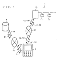
- FIG. 1 is a conceptual diagram illustrating a fault diagnosis system according to an embodiment of the present invention.
- FIG. 2 is a flowchart showing the operation of the fault diagnosis system.
- a diagnosis object equipment 1 which is an object to be subjected to fault diagnosis
- an air conditioner is illustrated in the fault diagnosis system.
- the diagnosis object equipment 1 has an outdoor unit 10 and indoor units 11, 12, ... connected to the outdoor unit 10.
- the fault diagnosis system also has a diagnosis terminal 2 and a fault diagnosis database 4 each of which is provided separately from the diagnosis object equipment 1.
- the diagnosis object equipment 1 and the diagnosis terminal 2 are connected to each other via a communication network 31 so that communication can be performed bidirectionally.
- the diagnosis terminal 2 is also separate from the fault diagnosis database 4.
- the diagnosis terminal 2 and the fault diagnosis database 4 are connected to each other via a communication network 32 so that communication can be performed bidirectionally.
- a communication network can be commonly used as the communication networks 31 and 32.
- the diagnosis terminal 2 transmits a first request signal 41 requesting for fault information 42 as information regarding a fault to the diagnosis object equipment 1 (see step S1 in FIG. 2).
- the diagnosis object equipment 1 can transmit the fault information 42 and, in response to the first request signal 41, transmits the fault information 42 to the diagnosis terminal 2 (see step S2 in FIG. 2).
- the fault information 42 includes, for example, information of identifying the model of the diagnosis object equipment 1 and information of identifying a fault part (such as the compressor of the outdoor unit 10 or the fan of the indoor unit 11) in the diagnosis object equipment 1.
- the fault diagnosis database 4 stores a plurality of kinds of the fault diagnosis programs 51, which correspond to various models of the diagnosis object equipment 1 and various fault parts, used in diagnosing a fault.
- the fault diagnosis database 4 transmits the fault diagnosis program 51 corresponding to the fault information 42 to the diagnosis terminal 2 on the basis of the second request signal 43 (see step S4 in FIG. 2).
- the fault information 42 is supplied to the fault diagnosis database 4, and a proper fault diagnosis program 51 may be selected in the fault diagnosis database 4.
- a proper fault diagnosis program 51 stored in the fault diagnosis database 4 may be designated on the basis of the contents of the fault information 42.
- the diagnosis terminal 2 obtains the fault diagnosis program 51 which is adapted to diagnose a fault in the compressor, that is, used in diagnosing the compressor from the fault diagnosis database 4.
- the diagnosis terminal 2 diagnoses a fault in the diagnosis object equipment 1 by using the fault diagnosis program 51 obtained by being received from the fault diagnosis database 4 as described above (see steps S5 and S6 in FIG. 2).
- a third request signal 52 is transmitted from the diagnosis terminal 2 to the diagnosis object equipment 1 (see step S5 in FIG. 2).
- the third request signal 52 requests for data indicative of the status of the diagnosis object equipment 1 necessary for fault diagnosis, such as temperature and pressure.
- the diagnosis object equipment 1 transmits a status signal 53 indicative of the requested status of itself to the diagnosis terminal 2 in response to the third request signal 52 (see step S6 in FIG. 2).
- the diagnosis terminal 2 which has received the status signal 53 continues the fault diagnosis in accordance with the fault diagnosis program 51.
- the components operate, and the status signal 53 is transmitted from the outdoor unit 10 to the diagnosis terminal 2 as data indicating how high pressure and low pressure of the outdoor unit 10, temperature at the inlet and outlet of a condenser, temperature at the inlet and outlet of an evaporator, and the like react.
- the fault diagnosis program 51 has data in a normal status and compares the status signal 53 with the data in the normal status, thereby diagnosing an abnormal state of the valves, clogging of a pipe, and whether a refrigerant amount is proper or not.
- a diagnosis result is displayed on the diagnosis terminal 2 (see step S7 in FIG. 2).
- the fault diagnosis system is constructed as described above, a fault is diagnosed by the steps as described above, and the diagnosis terminal 2 is employed as described above and used by the steps as described above, thereby obtaining the following effects.
- the diagnosis terminal 2 since the diagnosis terminal 2 is separate from the fault diagnosis database 4, the diagnosis terminal 2 does not have to store a number of fault diagnosis programs. It is sufficient to obtain the fault diagnosis program 51 necessary for diagnosing the diagnosis object equipment 1 from the fault diagnosis database 4. Therefore, excellent portability and reduction in cost can be realized.
- a new fault diagnosis program can be employed to carry out fault diagnosis by using the fault diagnosis database 4 and the diagnosis terminal 2.
- Such a fault diagnosis program can be added or updated for the fault diagnosis database 4 by using a known technique.
- the diagnosis terminal 2 obtains the fault information 42, transmits the second request signal 43 to the fault diagnosis database 4, and obtains the fault diagnosis program 51. Therefore, the diagnosis terminal 2 can obtain the fault diagnosis program 51 corresponding to a plurality of kinds of diagnosis object equipment and a plurality of kinds of fault parts and can diagnose a fault by using the fault diagnosis program 51.
- a cue of transmission of the first request signal 41 from the diagnosis terminal 2 to the diagnosis object equipment 1 is not limited to contact from the user to the service person.
- the control unit may urge the diagnosis terminal 2 to transmit the first request signal 41.
- FIG. 3 is a diagram showing a state where the diagnosis terminal 2 is connected to the diagnosis object equipment 1 via a connection line 6 and illustrates a modification of the present embodiment.
- the service person contacted by the user connects the diagnosis terminal 2 to the diagnosis object equipment 1 via the connection line 6.
- the first request signal 41 can be transmitted from the diagnosis terminal 2 to the diagnosis object equipment 1 by using a known technique such as "plug and play".
- Prediction of occurrence of a fault by using the fault diagnosis program 51 can be also easily realized in the present invention by, for example, properly designing the fault diagnosis program 51.
- the present invention can be easily applied to diagnosis of a kind other than a fault.
- the present invention can be applied to diagnosis of the life of the diagnosis object equipment 1.
- the present invention can be applied to the case of diagnosing the life of the compressor of the outdoor unit 10.
- the present invention can be also applied to the case of diagnosing whether the diagnosis object equipment 1 needs maintenance or not.
- the present invention can be applied to diagnose the cleaning timing of a heat exchanger, filter exchange timing, and the like of each of the indoor units 11, 12, ....
Landscapes
- Engineering & Computer Science (AREA)
- Physics & Mathematics (AREA)
- Theoretical Computer Science (AREA)
- General Engineering & Computer Science (AREA)
- General Physics & Mathematics (AREA)
- Computational Linguistics (AREA)
- Evolutionary Computation (AREA)
- Data Mining & Analysis (AREA)
- Computing Systems (AREA)
- Artificial Intelligence (AREA)
- Mathematical Physics (AREA)
- Software Systems (AREA)
- Computer Networks & Wireless Communication (AREA)
- Testing And Monitoring For Control Systems (AREA)
- Air Conditioning Control Device (AREA)
- Selective Calling Equipment (AREA)
Abstract
Description
Claims (20)
- A diagnosis system comprising:a diagnosis object equipment (1), as an object of diagnosis, capable of transmitting diagnosis information (42) as information regarding said diagnosis on said diagnosis object equipment;a diagnosis database (4), which is separate from said diagnosis object equipment, for storing a plurality of diagnosis programs (51) used in carrying out said diagnosis on said diagnosis object equipment; anda diagnosis terminal (2), which is separate from said diagnosis object equipment and said diagnosis database, for obtaining said diagnosis program from said diagnosis database on the basis of said diagnosis information, and carrying out said diagnosis by using said diagnosis program.
- The diagnosis system according to claim 1, wherein
said diagnosis information (42) includes information of identifying a model of said diagnosis object equipment (1), and
said diagnosis program (51) obtained from said diagnosis database (4) to said diagnosis terminal (2) corresponds to said model of said diagnosis object equipment. - The diagnosis system according to claim 1, wherein
said diagnosis information (42) includes information of identifying a diagnosis part in said diagnosis object equipment (1), and
said diagnosis program (51) obtained from said diagnosis database (4) to said diagnosis terminal (2) corresponds to said diagnosis part in said diagnosis object equipment. - The diagnosis system according to claim 3, wherein
said diagnosis program (51) tests operation of said diagnosis part. - The diagnosis system according to any one of claims 1 to 4, wherein
said diagnosis object equipment (1) transmits a status signal (53) indicative of the status of itself to said diagnosis terminal (2) in response to a request from said diagnosis program (51). - A diagnosis method comprising steps of:(a) transmitting information (42) as information regarding diagnosis on a diagnosis object equipment (1) as an object of diagnosis from said diagnosis object equipment to a diagnosis terminal (2) which is separate from said diagnosis object equipment (S2);(b) sending a request for transmission of a diagnosis program (51) used in carrying out said diagnosis from said diagnosis terminal to a diagnosis database (4) which is separate from each of said diagnosis object equipment and said diagnosis terminal (S3);(c) transmitting said diagnosis program corresponding to said diagnosis information from said diagnosis database to said diagnosis terminal (S4); and(d) carrying out said diagnosis by said diagnosis terminal by using said diagnosis program obtained in said step (c) (S5,S6).
- The diagnosis method according to claim 6, wherein
said diagnosis information (42) includes information of identifying a model of said diagnosis object equipment (1), and
said diagnosis program (51) transmitted from said diagnosis database (4) to said diagnosis terminal (2) corresponds to said model of said diagnosis object equipment. - The diagnosis method according to claim 6, wherein
said diagnosis information (42) includes information of identifying a diagnosis part in said diagnosis object equipment (1), and
said diagnosis program (51) transmitted from said diagnosis database (4) to said diagnosis terminal (2) corresponds to said diagnosis part in said diagnosis object equipment. - The diagnosis method according to claim 8, wherein
said diagnosis program (51) tests operation of said diagnosis part. - The diagnosis method according to any one of claims 6 to 9, wherein
said diagnosis object equipment (1) transmits a status signal (53) indicative of the status of itself to said diagnosis terminal in response to a request from said diagnosis program (51). - A diagnosis terminal (2) for receiving diagnosis information (42) as information regarding diagnosis on a diagnosis object equipment (1) from said diagnosis object equipment as an object of said diagnosis,
receiving a diagnosis program obtained on the basis of said diagnosis information from a diagnosis database (4) which is separate from said diagnosis object equipment and stores a plurality of said diagnosis programs (51), and
carrying out said diagnosis on said diagnosis object equipment by using said diagnosis program, wherein
said diagnosis terminal is separate each from said diagnosis object equipment and said diagnosis database. - The diagnosis terminal according to claim 11, wherein
said diagnosis information (42) includes information of identifying a model of said diagnosis object equipment (1), and
said diagnosis program (51) obtained from said diagnosis database (4) to said diagnosis terminal (2) corresponds to said model of said diagnosis object equipment. - The diagnosis terminal according to claim 11, wherein
said diagnosis information (42) includes information of identifying a diagnosis part in said diagnosis object equipment (1), and
said diagnosis program (51) obtained from said diagnosis database (4) to said diagnosis terminal (2) corresponds to said diagnosis part in said diagnosis object equipment. - The diagnosis terminal according to claim 13, wherein
said diagnosis program (51) tests operation of said diagnosis part. - The diagnosis terminal according to any of claims 11 to 14, wherein
said diagnosis object equipment (1) transmits a status signal (53) indicative of the status of itself to said diagnosis terminal (2) in response to a request from said diagnosis program (51). - A method of using a diagnosis terminal (2) which is separate each from a diagnosis object equipment (1) as an object of diagnosis and a diagnosis database (4) separate from said diagnosis object equipment, comprising steps of:(a) receiving diagnosis information (42) as information regarding said diagnosis on said diagnosis object equipment (1) from said diagnosis object equipment (S2);(b) requesting transmission of a diagnosis program (51) used in carrying out said diagnosis to said diagnosis database (S3);(c) receiving said diagnosis program corresponding to said diagnosis information from said diagnosis database (S4); and(d) carrying out said diagnosis by using said diagnosis program obtained in step (c) (SS,S6).
- The method of using a diagnosis terminal according to claim 16, wherein
said diagnosis information (42) includes information of identifying a model of said diagnosis object equipment (1), and
said diagnosis program (51) received from said diagnosis database (4) corresponds to said model of said diagnosis object equipment. - The method of using a diagnosis terminal according to claim 16, wherein
said diagnosis information (42) includes information of identifying a diagnosis part in said diagnosis object equipment (1), and
said diagnosis program (51) received from said diagnosis database (4) corresponds to said diagnosis part in said diagnosis object equipment. - The method of using a diagnosis terminal according to claim 18, wherein
said diagnosis program (51) tests operation of said diagnosis part. - The method of using a diagnosis terminal according to any one of claims 16 to 19, wherein
said diagnosis object equipment (1) transmits a status signal (53) indicative of the status of itself to said diagnosis terminal in response to a request from said diagnosis program (51).
Applications Claiming Priority (3)
| Application Number | Priority Date | Filing Date | Title |
|---|---|---|---|
| JP2001254671 | 2001-08-24 | ||
| JP2001254671A JP2003070080A (en) | 2001-08-24 | 2001-08-24 | Diagnostic system, diagnostic method, diagnostic terminal, and method of using diagnostic terminal |
| PCT/JP2002/008452 WO2003030580A1 (en) | 2001-08-24 | 2002-08-22 | Diagnosis system, diagnosis method, diagnosis terminal, and diagnosis terminal using method |
Publications (2)
| Publication Number | Publication Date |
|---|---|
| EP1427246A1 true EP1427246A1 (en) | 2004-06-09 |
| EP1427246A4 EP1427246A4 (en) | 2010-09-01 |
Family
ID=19082799
Family Applications (1)
| Application Number | Title | Priority Date | Filing Date |
|---|---|---|---|
| EP02765343A Withdrawn EP1427246A4 (en) | 2001-08-24 | 2002-08-22 | SYSTEM, METHOD AND TERMINAL FOR DIAGNOSIS, AND DIAGNOSTIC TERMINAL OPERATING ACCORDING TO THE METHOD DESCRIBED |
Country Status (4)
| Country | Link |
|---|---|
| EP (1) | EP1427246A4 (en) |
| JP (1) | JP2003070080A (en) |
| CN (1) | CN1547868A (en) |
| WO (1) | WO2003030580A1 (en) |
Families Citing this family (7)
| Publication number | Priority date | Publication date | Assignee | Title |
|---|---|---|---|---|
| JP4721952B2 (en) * | 2006-05-23 | 2011-07-13 | 三洋電機株式会社 | Air conditioner |
| KR101193374B1 (en) | 2006-07-28 | 2012-10-19 | 한라공조주식회사 | Method for testing action of air conditioning control device |
| JP2011242004A (en) * | 2010-05-14 | 2011-12-01 | Sanyo Electric Co Ltd | Operation check device of air conditioner |
| JP6147087B2 (en) * | 2013-05-23 | 2017-06-14 | 三菱電機株式会社 | Fault diagnosis device for vehicle air conditioner |
| WO2015037333A1 (en) * | 2013-09-10 | 2015-03-19 | 日立アプライアンス株式会社 | Air conditioner diagnostic system, air conditioner and mobile communication terminal |
| KR102419169B1 (en) * | 2016-03-25 | 2022-07-08 | 엘지전자 주식회사 | Monitoring device for air conditions apparatus |
| CN110296505A (en) * | 2019-07-11 | 2019-10-01 | 武汉奥特多电子科技有限公司 | A kind of internet of things type air-conditioner controller |
Family Cites Families (3)
| Publication number | Priority date | Publication date | Assignee | Title |
|---|---|---|---|---|
| JPH08178278A (en) * | 1994-12-28 | 1996-07-12 | Tokyo Gas Co Ltd | Repair method and repair support device for gas appliances |
| JPH08275265A (en) * | 1995-04-04 | 1996-10-18 | Tokyo Gas Co Ltd | Fault diagnosis device |
| JP2001154725A (en) * | 1999-11-30 | 2001-06-08 | Mitsubishi Motors Corp | Vehicle failure diagnosis method, vehicle failure diagnosis device, and computer-readable recording medium recording failure diagnosis program |
-
2001
- 2001-08-24 JP JP2001254671A patent/JP2003070080A/en active Pending
-
2002
- 2002-08-22 EP EP02765343A patent/EP1427246A4/en not_active Withdrawn
- 2002-08-22 CN CNA028165446A patent/CN1547868A/en active Pending
- 2002-08-22 WO PCT/JP2002/008452 patent/WO2003030580A1/en not_active Ceased
Also Published As
| Publication number | Publication date |
|---|---|
| WO2003030580A1 (en) | 2003-04-10 |
| JP2003070080A (en) | 2003-03-07 |
| CN1547868A (en) | 2004-11-17 |
| EP1427246A4 (en) | 2010-09-01 |
Similar Documents
| Publication | Publication Date | Title |
|---|---|---|
| US11009245B2 (en) | Method and system for proactively and remotely diagnosing an HVAC system | |
| EP3726157B1 (en) | Air-conditioning system, remote controller, and method for saving a history of operation data of an air conditioner | |
| CN112665306B (en) | Refrigerator remote fault diagnosis system and diagnosis method thereof | |
| JP4518208B2 (en) | Remote management system and remote management method for air conditioner | |
| JP2009002651A (en) | Abnormality diagnosis system | |
| CN109654662B (en) | Detection element control method and device and air conditioning unit | |
| JP4281334B2 (en) | Abnormality diagnosis system | |
| JP4052051B2 (en) | Fault diagnosis system and diagnostic server | |
| CN100578409C (en) | Equipment control method, equipment control device, and equipment repair system | |
| CN114510378A (en) | Parameter backup method and device for air conditioning unit and electronic equipment | |
| JP7395027B2 (en) | Remote monitoring system and remote monitoring method | |
| EP3745055A1 (en) | State analysis system and state analysis device | |
| JP3976320B2 (en) | Air conditioner failure diagnosis device | |
| WO2003030580A1 (en) | Diagnosis system, diagnosis method, diagnosis terminal, and diagnosis terminal using method | |
| JP2009002650A (en) | Abnormality diagnosis system | |
| JP4550253B2 (en) | Remote monitoring system for air conditioner and monitoring method for indoor unit | |
| JP3858827B2 (en) | Information management system | |
| CN113294888B (en) | Air conditioner fault diagnosis method and device, engineering fault diagnosis method and system and air conditioner | |
| JP2005309724A (en) | Abnormality diagnosis system and abnormality diagnosis method | |
| CN112611082A (en) | Air conditioning unit and control method thereof | |
| JPH1019341A (en) | Air conditioner remote monitoring system | |
| JP2017053551A (en) | Remote monitoring device, remote monitoring method and refrigeration cycle device | |
| CN100437510C (en) | Orderly recording of system-wide faults in hvac systems | |
| JP2005098633A (en) | Two-stage compressor mounted cryogenic equipment diagnostic device, cryogenic equipment remote monitoring system | |
| JP7630657B2 (en) | Equipment management device, equipment management system, and data processing method for equipment management system |
Legal Events
| Date | Code | Title | Description |
|---|---|---|---|
| PUAI | Public reference made under article 153(3) epc to a published international application that has entered the european phase |
Free format text: ORIGINAL CODE: 0009012 |
|
| 17P | Request for examination filed |
Effective date: 20040304 |
|
| AK | Designated contracting states |
Kind code of ref document: A1 Designated state(s): AT BE BG CH CY CZ DE DK EE ES FI FR GB GR IE IT LI LU MC NL PT SE SK TR |
|
| RTI1 | Title (correction) |
Free format text: DIAGNOSIS SYSTEMSS; DIAGNOSIS METHOD; DIAGNOSIS TERMINAL;AND DIAGNOSIS TERMINAL USING METHOD |
|
| RIC1 | Information provided on ipc code assigned before grant |
Ipc: G06N 5/02 20060101AFI20100722BHEP |
|
| A4 | Supplementary search report drawn up and despatched |
Effective date: 20100804 |
|
| 17Q | First examination report despatched |
Effective date: 20101216 |
|
| STAA | Information on the status of an ep patent application or granted ep patent |
Free format text: STATUS: THE APPLICATION IS DEEMED TO BE WITHDRAWN |
|
| 18D | Application deemed to be withdrawn |
Effective date: 20110427 |