EP1427071A2 - Modular jack - Google Patents
Modular jack Download PDFInfo
- Publication number
- EP1427071A2 EP1427071A2 EP03026364A EP03026364A EP1427071A2 EP 1427071 A2 EP1427071 A2 EP 1427071A2 EP 03026364 A EP03026364 A EP 03026364A EP 03026364 A EP03026364 A EP 03026364A EP 1427071 A2 EP1427071 A2 EP 1427071A2
- Authority
- EP
- European Patent Office
- Prior art keywords
- terminals
- portions
- fixed
- modular jack
- modular
- Prior art date
- Legal status (The legal status is an assumption and is not a legal conclusion. Google has not performed a legal analysis and makes no representation as to the accuracy of the status listed.)
- Withdrawn
Links
Images





Classifications
-
- H—ELECTRICITY
- H01—ELECTRIC ELEMENTS
- H01R—ELECTRICALLY-CONDUCTIVE CONNECTIONS; STRUCTURAL ASSOCIATIONS OF A PLURALITY OF MUTUALLY-INSULATED ELECTRICAL CONNECTING ELEMENTS; COUPLING DEVICES; CURRENT COLLECTORS
- H01R24/00—Two-part coupling devices, or either of their cooperating parts, characterised by their overall structure
- H01R24/60—Contacts spaced along planar side wall transverse to longitudinal axis of engagement
- H01R24/62—Sliding engagements with one side only, e.g. modular jack coupling devices
- H01R24/64—Sliding engagements with one side only, e.g. modular jack coupling devices for high frequency, e.g. RJ 45
Definitions
- the present invention relates to a modular jack in which a modular plug is plugged.
- a modular jack is one of conventional connectors which are used in telephone equipment or local area net-work (LAN).
- the modular jack is usually mounted on a circuit board and the modular plug, which connects a plurality of core wires, such as cables, to each other, is plugged in the modular jack.
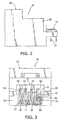
- the modular jack comprises a housing body and eight terminals (the first to eighth terminals 3, 4, 5, 6, 7, 8, 9, and 10) provided in the housing body.
- the housing body is composed of an insert 11 and a modular jack assembly 12 for receiving the insert 11.
- the insert 11 is composed of a rear wall 13 and a top wall 14 extending forwardly from the top of the rear wall 13.
- a predetermined number of upper grooves 15 are formed on the upper surfaces of the rear and top walls 13 and 14 and a predetermined number of rear grooves 16 are formed on the rear surface of the rear wall 13 such that the rear grooves 16 continues from the upper grooves 15 and extend in a vertical direction.
- the respective terminals 3 to 10 are fixed to the rear wall 17 via an extended portion 17 and divided into two groups in accordance with the shapes thereof to reduce the electrical cross-talk.
- the first group consists of the first, third, fifth, and eighth terminals 3, 5, 7, and 10
- the second group consists of the second, fourth, sixth, and seventh terminals 4, 6, 8, and 9.
- the respective terminals 3, 5, 7, and 10 of the first group have a fixed portion 18 fixed to a board 26, a vertical portion 19 extending vertically along the rear groove 16, a horizontal portion 20 extending horizontally along the upper groove 15, and a contact portion 21 folded back obliquely in a lower back direction at the end of the horizontal portion 20.
- the top of the contact portion 21 is a free end.
- the respective terminals 4, 6, 8, and 9 of the second group have a fixed portion 22 fixed to a board 26, a vertical portion 23 extending vertically along the rear groove 16, a horizontal portion 24 extending horizontally along the upper surface of the rear wall 13, and a contact portion 25 curved downwardly from the end of the horizontal portion 24 and then extending obliquely in an upper forward direction.
- the top end of the contact portion 25 is supported by the front end of the top wall 14.
- the modular jack assembly 12 is mounted on the circuit board 26 and comprises sixteen receiving cavities 27 and 28 arranged in two-stage at the front side thereof.
- the insert 11 and the terminals 3 to 10 are arranged in the receiving cavity 28 of the lower stage and other insert and terminals (not shown) are arranged in the receiving cavity of the upper stage.
- the respective receiving cavities 27 and 28 are provided with plug-in cavities (not shown) in which the modular plugs are plugged.
- the contact portions 21 and 25 of the terminals 3 to 10 of the first and second groups are brought into contact with terminals (not shown) of the modular plug for electrical connection between the modular jack and plug.
- the contact portions 21 of the terminals 3, 5, 7, and 10 of the first group are bent in the oblique lower back direction from the front end of the top wall 14 after the terminals are fixed to the insert 11. Accordingly, long-time assembly work and lengthy terminals are required, which makes it difficult to reduce the assembling and material costs. Also, a sufficient height of the housing body is necessary for bending the contact portions 21 in the oblique lower back direction, which makes it difficult to minimize the size of the housing body in the heightwise direction and the size of the modular jack.
- the housing body is composed of the insert 11 and modular jack assembly 12, which incorporate the respective terminals 3 to 10 into the housing body, it is difficult to reduce the number of parts and the manufacturing cost cannot be reduced.
- Figs. 1-7 show a modular jack 41 for high-speed signals according to an embodiment of the invention.
- the modular jack 41 comprises a housing body 42 and a predetermined number (eight in the drawings) of terminals, the first to eighth terminals 43, 44, 45, 46, 47, 48, 49, and 50, and is mountable on a board 51.
- the housing body 42 is provided with a plugging cavity 52 in the front side thereof so that a modular plug 75 (Figs. 6 and 7) can be plugged in the cavity 52.
- a lock member receiving portion 53 is provided in the upper side of the cavity 52 and eight grooves 55 extending long in a back-and-forth direction are provided on the inner surface of a bottom wall 54 of the housing body 42.
- First and second terminal slits 57 and 58 having vertically long shapes are provided in the rear wall 56 of the housing body 42.
- the first and second slits 57 and 58 are composed of four grooves, respectively, which are arranged alternately.
- First and second extended fixed portions 59 and 60 are provided at the upper side of the first terminal slits 57 and the lower side of the second terminal slits 58, respectively. It is preferable that the first fixed portion 59 is disposed above the upper side of the second terminal slits 58 and the second fixed portion 60 is disposed below the lower side of the first terminal slits 57. By this arrangement, there is provided a sufficient thickness of the housing body 42 between the respective first terminal slits 59 and the respective second fixed portions 60 so that high strength of the housing body 42 is obtained.
- a cavity 61 is provided in the rear wall 56 such that the cavity 61 surrounds the four second terminal slits 58 and a pair of board fixed portions 62 extend rearwardly from both sides of the rear wall 56 so that the housing body 42 can be fixed to the board 51 via the board fixed portions 62.
- the terminals 43 to 50 are divided into two groups in accordance with the shapes thereof.
- the first group consists of the second, fourth, sixth, and eighth terminals 44, 46, 48, and 50
- the second group consists of the first, third, fifth, and seventh terminals 43, 45, 47, and 49.
- Fig. 1 The terminals 43 to 50 are divided into two groups in accordance with the shapes thereof.
- the first group consists of the second, fourth, sixth, and eighth terminals 44, 46, 48, and 50
- the second group consists of the first, third, fifth, and seventh terminals 43, 45, 47, and 49.
- each of the terminals 44, 46, 48, and 50 of the first group has a vertical portion 63 of which lower end is fixed to a board 51, a horizontal portion 65 having an extended portion 64 at the front end thereof press-fitted into the first fixed portion 59, a contact portion 66 extending downwardly along the inner surface of the rear wall 56 and then in an oblique lower forward direction, and a curved portion 67 curved outwardly from the front end f the contact portion 66.
- the distance between the lowermost end 68 of the curved portion 67 and the extended portion 64 is made smaller that the height of the first terminal slit 57 so that each terminal can be inserted into the first terminal slit 57 from the rear side of the housing body 42.
- each of the terminals 43, 45, 47, and 49 of the second group has a vertical portion 69 of which lower end is fixed to a board 51, an extended portion 70 extending downwardly from the upper end of the vertical portion 69 along the cavity 61 and press-fitted into the second fixed portion 60, a contact portion 71 extending upwardly along the inner surface of the rear wall 56 and then in an oblique lower forward direction, and a curved portion 72 curved outwardly from the front end f the contact portion 71.
- the distance between the extended portion 70 and the uppermost end 73 of the contact portion 71 is made smaller that the height of the second terminal slit 58 so that each terminal can be inserted into the second terminal slit 58 from the rear side of the housing body 42. It is preferable that the angle of inclination of the contact portions 71 of the terminals 43, 45, 47, and 49 of the second group is made different from that of the contact portions 66 of the terminals 44, 46, 48, and 50 of the first group.
- the position in the back-and-fourth direction, of the curved portion 72 of the terminals 43, 45, 47, and 49 of the second group is made different from that of the curved portions 67 of the terminals 44, 46, 48, and 50 of the first group.
- the terminals 44, 46, 48, and 50 of the first group is fixed (press-fitted) to the housing body 42 at the upper position of the first terminal slits 57 and the terminals 43, 45, 47, and 49 of the second group is fixed (press-fitted) to the housing body 42 at the lower position of the second terminal slits 58 so that the distance between the terminals of the first and second groups is made large and there is almost no overlapped portion of the terminals of the first and second groups when viewed from side.
- the top ends of the terminals are made free ends and the length of the terminals is made short so that the transmission path can be made short. Consequently, the cross-talk between the adjacent terminals is reduced so that the modular jack readily corresponds to high-speed signals.
- the terminals 44, 46, 48, and 50 of the first group are inserted into the first terminal slits 57 and the terminals 43, 45, 47, and 49 of the second group are inserted into the second terminal slits 58 from the rear side of the housing body 42.
- the extended portions 64 and 70 are press-fitted to the first and second fixed portions 59 and 60, respectively so that the respective terminals 43 to 50 extend to the plugging cavity 52, cantilevered with the support by the first and second fixed portion 59 and 60.
- the respective terminals are firmly held in the housing body 42 and the respective curved portions 67 and 72 of the terminals 43 to 50 are positioned above the long grooves 55.
- the terminals 43 to 50 can be easily installed to the housing body 42 by inserting them into the first and second fixed portions 59 and 60 from the rear side of the housing body 42 and the bending work of the terminals is not necessary after the insertion so that the assembly of the terminals can be made simple.
- the terminals 43 to 50 are cantilevered by the first and second fixed portions 59 and 60 and extend forwardly so that the terminals 43-50 is short, the transmission path is also short, and the material cost can be reduced.
- respective contact portions 66 and 71 have no folded portions, the height of the housing body 42 can be made small, which enables the miniaturization of the modular jack.
- the housing body 42 is composed of only one part, the manufacturing cost can be reduced.
- the contact portions 66 and 71 flex downwardly and the front ends thereof are accommodated in the long grooves 55 so that the terminals 77 of the modular plug 75 and the terminals 43-50 of the modular jack 41 are brought into contact with each other at a predetermined pressure, thus electrically connecting the modular plug and jack 75 and 41. Since the curved portions 67 and 72 are provided in the respective terminals 43-50, the plugging operation between the modular plug and jack 75 and 41 is performed smoothly.
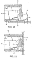
- a first control portions 81 (Fig. 8) and a second control portions 82 (Fig. 9) can be provided in the inner surface of the bottom wall 54 of the housing body 42.
- the first and second control portions 81 and 82 are provided at positions corresponding to those of the respective contact portions 66 and 71 of terminals of the first and second groups and formed in the form of comb teeth so that they do not interfere with the terminal arrangement grooves of the modular plug 75.
- Inclined faces 83 and 84 having inclinations corresponding to the contact portions 66 and 71, respectively, are provided on the upper sides of the first and second control portions 81 and 82 such that when the modular plug 75 is plugged in the modular jack 41 (in the condition of Figs.
- the contact portions 66 and 71 can flex toward the first and second control portions 81 and 82, respectively, until they come close to or abut against the first and second control portions 81 and 82.
- the bottom wall 54 ahead of the first and second control portions 81 and 82 are opened due to reasons for manufacture. In this case, when a deformed or different kind of modular plug is attempted to be plugged in the modular jack 41, the contact portions 66 and 71 of the modular jack 41 are not properly positioned at the terminal arrangement grooves of the modular plug and unnaturally strong force is exerted on the respective contact portion 66 and 71 by the pressure from the top end of the modular plug.
- the contact portions 66 and 71 are not broken because they abut against the first and second control portions 81 and 82 and do not flex any more.
- the resilient force of the terminals is weaken and the terminals are prone to be broken.
- the first and second control portions 81 and 82 prevent the terminals from being broken.
- the modular jack 41 is mounted on the board 51 via the board fixed portion 62.
- the modular jack 41 is mounted on the board 51 via the bottom wall 54, rear wall 56, and top wall 74 of the housing body 42, respectively.
- the modular jack 41 corresponds to high-speed signals.
- the invention is applicable to a modular jack for low-speed signals, such as telephone line.
- all terminals 43-50 may have the same shape so that the manufacturing cost of the terminals is further reduced.
- the terminals 43-50 may be divided into three groups instead of two groups in accordance with the shape thereof. Also, the shapes of the respective terminals 43-50 are not limited to the above-mentioned shapes.
- the shapes of the first and second terminal slits 57 and 58 may be different as far as it can fix the terminals.
- it may be the form of a groove after removing the bottom wall 54.
- the terminals can be easily fixed to the fixed portions of the rear wall by inserting them into the cavities provided in the rear walls, the terminals extend to the plugging cavity, cantilevered by the fixed portions, and the housing body is composed of one part so that it is possible to simplify the assembly work, reduce the cross-talk, reduce the number of parts, and reduce the manufacturing cost.
Landscapes
- Details Of Connecting Devices For Male And Female Coupling (AREA)
- Coupling Device And Connection With Printed Circuit (AREA)
- Connector Housings Or Holding Contact Members (AREA)
Abstract
Description
Claims (5)
- A modular jack in which a modular plug is plugged, comprising:a housing body including a cavity at a front side thereof in which said modular plug is plugged and a rear wall having openings and fixed portions; anda plurality of terminals fixed to said fixed portions and extend to said cavity in a form of cantilevered beams supported by said fixed portions, wherein said terminals are inserted into said openings to be fixed to said fixed portions.
- The modular jack according to claim 1, wherein said fixed portions include first and second fixed portions spaced from each other in a heightwise direction of said modular jack by a predetermined distance, wherein said first and second fixed portions are arranged alternately.
- The modular jack according to claim 2, wherein said terminals include first terminals which are fixed to said first fixed portions and second terminals which are fixed to said second fixed portions, wherein said respective first terminals have first forwardly inclined contact portions and said second respective terminals have second forwardly inclined contact portions, said first and second inclined contact portions having angles of inclinations which are different from each other.
- The modular jack according to claim 3, wherein said first and second inclined contact portions have first and second curved sections, respectively, at front ends thereof, said first and second curved sections being disposed at different positions from each other in a back-and-forth direction.
- The modular jack according to claim 1, wherein said housing has a plurality of control portions in a bottom wall thereof at positions corresponding to those of said terminals so that said terminals abut against said control portions to prevent excessive flexure of said terminals.
Applications Claiming Priority (2)
| Application Number | Priority Date | Filing Date | Title |
|---|---|---|---|
| JP2002335127A JP4048102B2 (en) | 2002-11-19 | 2002-11-19 | Modular jack |
| JP2002335127 | 2002-11-19 |
Publications (2)
| Publication Number | Publication Date |
|---|---|
| EP1427071A2 true EP1427071A2 (en) | 2004-06-09 |
| EP1427071A3 EP1427071A3 (en) | 2007-03-28 |
Family
ID=32310625
Family Applications (1)
| Application Number | Title | Priority Date | Filing Date |
|---|---|---|---|
| EP03026364A Withdrawn EP1427071A3 (en) | 2002-11-19 | 2003-11-18 | Modular jack |
Country Status (3)
| Country | Link |
|---|---|
| US (1) | US6776667B2 (en) |
| EP (1) | EP1427071A3 (en) |
| JP (1) | JP4048102B2 (en) |
Families Citing this family (5)
| Publication number | Priority date | Publication date | Assignee | Title |
|---|---|---|---|---|
| JP4905243B2 (en) * | 2007-05-07 | 2012-03-28 | サンケン電気株式会社 | Electrical equipment with LAN line connector and operation unit |
| US7427218B1 (en) * | 2007-05-23 | 2008-09-23 | Commscope, Inc. Of North Carolina | Communications connectors with staggered contacts that connect to a printed circuit board via contact pads |
| US7794286B2 (en) * | 2008-12-12 | 2010-09-14 | Hubbell Incorporated | Electrical connector with separate contact mounting and compensation boards |
| US9118134B2 (en) * | 2013-03-01 | 2015-08-25 | Panduit Corp. | RJ-45-compatible communication connector with contacts having wider distal ends |
| JP2025060290A (en) * | 2023-09-29 | 2025-04-10 | パナソニックIpマネジメント株式会社 | Modular jack and wiring device equipped with same |
Family Cites Families (9)
| Publication number | Priority date | Publication date | Assignee | Title |
|---|---|---|---|---|
| GB8924898D0 (en) * | 1989-11-03 | 1989-12-20 | Commtel Consumer Electronics P | Telephone extension socket |
| US5011435A (en) * | 1990-04-05 | 1991-04-30 | Molex Incorporated | Modular jack |
| US5186649A (en) * | 1992-04-30 | 1993-02-16 | At&T Bell Laboratories | Modular plug having enhanced cordage strain relief provisions |
| WO1998005100A1 (en) * | 1996-07-26 | 1998-02-05 | Berg Technology, Inc. | Modular telephone connector with a floating spring contact |
| TW383923U (en) * | 1998-11-20 | 2000-03-01 | Hon Hai Prec Ind Co Ltd | Electrical connector |
| US6093060A (en) * | 1999-03-11 | 2000-07-25 | The Whitaker Corporation | Electrical connector assembled with a terminal array that is connected by a carrier strip |
| US6280256B1 (en) | 1999-04-01 | 2001-08-28 | Bergtechnology, Inc. | Electrical connector for reducing electrical crosstalk and common mode electromagnetic interference |
| TW479861U (en) * | 2000-01-25 | 2002-03-11 | Hon Hai Prec Ind Co Ltd | Electrical connector |
| US6461200B1 (en) * | 2001-12-11 | 2002-10-08 | Hon Hai Precision Ind. Co., Ltd. | Electrical connector assembly |
-
2002
- 2002-11-19 JP JP2002335127A patent/JP4048102B2/en not_active Expired - Fee Related
-
2003
- 2003-11-17 US US10/713,200 patent/US6776667B2/en not_active Expired - Fee Related
- 2003-11-18 EP EP03026364A patent/EP1427071A3/en not_active Withdrawn
Also Published As
| Publication number | Publication date |
|---|---|
| US20040102100A1 (en) | 2004-05-27 |
| EP1427071A3 (en) | 2007-03-28 |
| JP4048102B2 (en) | 2008-02-13 |
| US6776667B2 (en) | 2004-08-17 |
| JP2004171878A (en) | 2004-06-17 |
Similar Documents
| Publication | Publication Date | Title |
|---|---|---|
| CN1218441C (en) | Electric power connector | |
| EP1635425B1 (en) | Connection terminal | |
| US6368160B2 (en) | Electrical connector assembly having an anti-mismating mechanism | |
| EP0232521A2 (en) | Low profile jack | |
| EP0994535A2 (en) | Modular connector with reduced crosstalk | |
| US20060228932A1 (en) | Electrical Connector, Wire Harness, and Method for Arranging Wire Harness | |
| WO1997027650A1 (en) | Multi-directional interface header assembly | |
| US20070155218A1 (en) | Cable connector assembly with internal printed circuit board | |
| EP0740372B1 (en) | Electrical connector | |
| EP0582264B1 (en) | Electrical connector for printed circuit boards | |
| EP2040337B1 (en) | Electrical connector | |
| EP0996993B1 (en) | Latched and shielded electrical connectors | |
| US8485850B2 (en) | Telecommunications connector | |
| JP7655777B2 (en) | Terminals, wire connectors and wire-to-board connectors | |
| US20010005653A1 (en) | Double row modular gang jack for board edge application | |
| US20070281547A1 (en) | Electrical connector having staggered contacts | |
| US6579129B2 (en) | Connector assembly | |
| EP0601265B1 (en) | Socket-type multipolar electrical connector | |
| US6776667B2 (en) | Modular jack | |
| EP0393879A2 (en) | Electrical connector system and insulation displacement terminals therefor | |
| JPH09129294A (en) | Modular jack assembly | |
| US5902154A (en) | Electrical connector | |
| US20040053537A1 (en) | Connector | |
| JP3304690B2 (en) | Interconnection terminals and joint connectors | |
| US6341964B1 (en) | Memory card connector |
Legal Events
| Date | Code | Title | Description |
|---|---|---|---|
| PUAI | Public reference made under article 153(3) epc to a published international application that has entered the european phase |
Free format text: ORIGINAL CODE: 0009012 |
|
| AK | Designated contracting states |
Kind code of ref document: A2 Designated state(s): AT BE BG CH CY CZ DE DK EE ES FI FR GB GR HU IE IT LI LU MC NL PT RO SE SI SK TR |
|
| AX | Request for extension of the european patent |
Extension state: AL LT LV MK |
|
| PUAL | Search report despatched |
Free format text: ORIGINAL CODE: 0009013 |
|
| AK | Designated contracting states |
Kind code of ref document: A3 Designated state(s): AT BE BG CH CY CZ DE DK EE ES FI FR GB GR HU IE IT LI LU MC NL PT RO SE SI SK TR |
|
| AX | Request for extension of the european patent |
Extension state: AL LT LV MK |
|
| 17P | Request for examination filed |
Effective date: 20070905 |
|
| AKX | Designation fees paid |
Designated state(s): DE FR GB |
|
| 17Q | First examination report despatched |
Effective date: 20080515 |
|
| STAA | Information on the status of an ep patent application or granted ep patent |
Free format text: STATUS: THE APPLICATION IS DEEMED TO BE WITHDRAWN |
|
| 18D | Application deemed to be withdrawn |
Effective date: 20081126 |