EP1427060A1 - Connector with piercing contact - Google Patents
Connector with piercing contact Download PDFInfo
- Publication number
- EP1427060A1 EP1427060A1 EP03027226A EP03027226A EP1427060A1 EP 1427060 A1 EP1427060 A1 EP 1427060A1 EP 03027226 A EP03027226 A EP 03027226A EP 03027226 A EP03027226 A EP 03027226A EP 1427060 A1 EP1427060 A1 EP 1427060A1
- Authority
- EP
- European Patent Office
- Prior art keywords
- cable
- receptacle
- contacts
- piercing
- contacting
- Prior art date
- Legal status (The legal status is an assumption and is not a legal conclusion. Google has not performed a legal analysis and makes no representation as to the accuracy of the status listed.)
- Withdrawn
Links
- 239000004020 conductor Substances 0.000 claims abstract description 47
- XLYOFNOQVPJJNP-UHFFFAOYSA-N water Substances O XLYOFNOQVPJJNP-UHFFFAOYSA-N 0.000 claims description 2
- 239000000428 dust Substances 0.000 claims 1
- 239000002245 particle Substances 0.000 claims 1
- 238000009413 insulation Methods 0.000 description 3
- 238000000034 method Methods 0.000 description 3
- 230000035515 penetration Effects 0.000 description 3
- 230000001419 dependent effect Effects 0.000 description 2
- 238000011161 development Methods 0.000 description 2
- 230000018109 developmental process Effects 0.000 description 2
- 238000002788 crimping Methods 0.000 description 1
- 238000011549 displacement method Methods 0.000 description 1
- 230000001747 exhibiting effect Effects 0.000 description 1
- 238000007789 sealing Methods 0.000 description 1
Images



Classifications
-
- H—ELECTRICITY
- H01—ELECTRIC ELEMENTS
- H01R—ELECTRICALLY-CONDUCTIVE CONNECTIONS; STRUCTURAL ASSOCIATIONS OF A PLURALITY OF MUTUALLY-INSULATED ELECTRICAL CONNECTING ELEMENTS; COUPLING DEVICES; CURRENT COLLECTORS
- H01R24/00—Two-part coupling devices, or either of their cooperating parts, characterised by their overall structure
- H01R24/66—Two-part coupling devices, or either of their cooperating parts, characterised by their overall structure with pins, blades or analogous contacts and secured to apparatus or structure, e.g. to a wall
- H01R24/70—Two-part coupling devices, or either of their cooperating parts, characterised by their overall structure with pins, blades or analogous contacts and secured to apparatus or structure, e.g. to a wall with additional earth or shield contacts
-
- H—ELECTRICITY
- H01—ELECTRIC ELEMENTS
- H01R—ELECTRICALLY-CONDUCTIVE CONNECTIONS; STRUCTURAL ASSOCIATIONS OF A PLURALITY OF MUTUALLY-INSULATED ELECTRICAL CONNECTING ELEMENTS; COUPLING DEVICES; CURRENT COLLECTORS
- H01R12/00—Structural associations of a plurality of mutually-insulated electrical connecting elements, specially adapted for printed circuits, e.g. printed circuit boards [PCB], flat or ribbon cables, or like generally planar structures, e.g. terminal strips, terminal blocks; Coupling devices specially adapted for printed circuits, flat or ribbon cables, or like generally planar structures; Terminals specially adapted for contact with, or insertion into, printed circuits, flat or ribbon cables, or like generally planar structures
- H01R12/50—Fixed connections
- H01R12/59—Fixed connections for flexible printed circuits, flat or ribbon cables or like structures
- H01R12/65—Fixed connections for flexible printed circuits, flat or ribbon cables or like structures characterised by the terminal
- H01R12/67—Fixed connections for flexible printed circuits, flat or ribbon cables or like structures characterised by the terminal insulation penetrating terminals
-
- H—ELECTRICITY
- H01—ELECTRIC ELEMENTS
- H01R—ELECTRICALLY-CONDUCTIVE CONNECTIONS; STRUCTURAL ASSOCIATIONS OF A PLURALITY OF MUTUALLY-INSULATED ELECTRICAL CONNECTING ELEMENTS; COUPLING DEVICES; CURRENT COLLECTORS
- H01R2107/00—Four or more poles
-
- H—ELECTRICITY
- H01—ELECTRIC ELEMENTS
- H01R—ELECTRICALLY-CONDUCTIVE CONNECTIONS; STRUCTURAL ASSOCIATIONS OF A PLURALITY OF MUTUALLY-INSULATED ELECTRICAL CONNECTING ELEMENTS; COUPLING DEVICES; CURRENT COLLECTORS
- H01R4/00—Electrically-conductive connections between two or more conductive members in direct contact, i.e. touching one another; Means for effecting or maintaining such contact; Electrically-conductive connections having two or more spaced connecting locations for conductors and using contact members penetrating insulation
- H01R4/24—Connections using contact members penetrating or cutting insulation or cable strands
- H01R4/2404—Connections using contact members penetrating or cutting insulation or cable strands the contact members having teeth, prongs, pins or needles penetrating the insulation
- H01R4/2406—Connections using contact members penetrating or cutting insulation or cable strands the contact members having teeth, prongs, pins or needles penetrating the insulation having needles or pins
Definitions
- the invention relates to a connector having at least one piercing contact for contacting the conductors of a cable, in particular the stranded conductors of a ribbon cable, according to the precharacterising clause of claim 1.
- connectors For solderless contacting of the conductors of a cable, connectors are used which produce an electrical contact by means of various connection methods, for example crimping or insulation displacement methods. Connectors are also known which allow contacting of a cable by penetration methods. These connectors comprise one or more pointed piercing contacts in the form of lances or spikes, which, upon connection of the connector to a cable, penetrate the insulation and sheath of the conductor(s) and contact the conductor(s), so avoiding prior removal of the insulation from the conductor(s). Contacting may also be effected at any desired point of a cable, without cutting the cable open at the contact point, such that a plurality of connectors equipped with piercing contacts may be fitted to a cable.
- An object of the present invention is to provide a more flexible connector, which in particular allows contacting of different cables.
- the connector according to the invention comprises a receptacle for receiving a cable and a contacting device having at least one piercing contact, wherein the contacting device may be positioned on the receptacle in such a way that the piercing contact comes to lie in a variable position in the receptacle.
- the contacting device in a particularly advantageous development of the connector, provision is made for the contacting device to comprise a plurality of piercing contacts arranged in a line with constant spacing, which contacts allow contacting of a corresponding number of equally spaced conductors of a ribbon cable.
- the line of piercing contacts may be so oriented relative to the receptacle and thus to the cable that the distance between the piercing contacts perpendicular to the cable matches exactly the distance between the conductors of the cable. This makes it possible to contact ribbon cables with different spacing patterns with just one connector.
- the contacting device is in two parts and comprises a holder, which may be positioned on the receptacle in a predetermined position, and a rotary unit mounted rotatably in the holder and provided with piercing contacts arranged in a line with constant spacing.
- a holder which may be positioned on the receptacle in a predetermined position
- a rotary unit mounted rotatably in the holder and provided with piercing contacts arranged in a line with constant spacing.
- the contacting device prefferably has markings which identify particular positions of the rotary unit relative to the holder and thus particular conductor spacings of a ribbon cable, so making possible quick contacting of the cable without prior adjustment of the rotary unit to a conductor spacing.
- the contacting device preferably also comprises a latching means, which fixes the rotary unit in particular positions in the holder. In this way, the risk is prevented of imprecise positioning of the rotary unit or slippage of the rotary unit out of a particular position during the contacting process and of associated miscontacting.
- Figure 1 is a schematic representation, in plan view, of a line of four piercing contacts 2 1 a to 21d arranged next to one another with constant spacing and which each contact a conductor 8a to 8d of a four-core ribbon cable 6.
- the longitudinal axis of the ribbon cable 6 is designated 11 while a transverse axis perpendicular thereto is designated 12.
- the individual conductors 8a to 8d of the ribbon cable 6 exhibit a spacing A. Since this spacing A corresponds to the mutual spacing of the piercing contacts 21a to 21d, the line of piercing contacts 21a to 21d is oriented perpendicularly to the cable 6 on the transverse axis 12.
- Figure 2 is a further schematic representation, in plan view, of a line of piercing contacts 21a to 21d which contact the conductors 9a to 9d of a ribbon cable 7 exhibiting a smaller conductor spacing B than the spacing A of the piercing contacts 21a to 21d. So that each of the piercing contacts 21a to 21d comes to lie over one of conductors 9a to 9d, the line of piercing contacts 21a to 21d is rotated by an angle ⁇ relative to the transverse axis 12 of the ribbon cable 7.
- the axis of rotation 10, about which the piercing contacts 21a to 21d are rotated, is fixed, in the Figure illustrated, by the point of intersection of longitudinal and transverse axes 11 and 12 of the ribbon cable 7 and extends centrally between the piercing contacts 21a to 21d perpendicularly to the plane common to the two axes 11 and 12. It is possible, of course, to orient an axis of rotation to the side of the piercing contacts, as shown in Figure 6, for example.
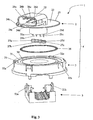
- FIG. 3 is a perspective representation of the components of an embodiment of a connector 1 according to the invention.
- the connector 1 has a contacting device 4 constructed in two parts, with a rotary unit 2 and a holder 3.
- the rotary unit 2 is provided with four piercing contacts 21a to 21d, which take the form of pointed spikes.
- Such piercing contacts are particularly suitable for contacting the commonly used stranded conductors, whose wires are pushed apart by the piercing contacts upon penetration of a conductor so as to achieve contacting.
- connectors are of course feasible which have more or fewer than the four piercing contacts 21a to 21d illustrated.
- the piercing contacts 21a to 21d are in turn connected with plug contacts 26a to 26d of a plug 25 on the top of the rotary unit 2.
- An electrical connection may be produced at this point by means of a cable with corresponding socket contacts of a socket.
- the rotary unit 2 also has a circular bearing surface 22, by means of which the rotary unit 2 is rotatably mounted in a corresponding recess 31 in the holder 3.
- the recess 31 in the holder 3 is provided with an additional annular depression 34, into which a correspondingly shaped sealing ring 35 may be inserted against the penetration of dirt and water.
- Corresponding protection of the piercing contacts 21 a to 21d is provided by cylindrical seals 27a to 27d surrounding them.
- Resiliently fitted clips 32a, 32b, 32c are arranged at the edge of the holder 3 and lock the bearing surface 22 of the rotary unit 2, once inserted, in such a way that the rotary unit 2 can only be rotated relative to the holder 3. Furthermore, a latching means is provided for user-friendly and secure adjustment of the contacting device 4 to particular conductor spacings, corresponding to particular positions of the rotary unit 2 in the holder 3. To this end, the edge of the bearing surface 22 of the rotary unit 2 is provided with an annular raised portion 23, which is interrupted at defined positions by recesses 24a to 24d. Latching in place of the rotary unit 2 is achieved by means of the clip 32a, which may engage in the recesses 24a to 24d and fix the rotary unit 2.
- the recesses 24a to 24d also have additional markings identifying the contactable ribbon cable conductor spacings to which they may be adjusted.
- the holder 3 of the contacting device 4 may be placed in a predetermined position on a receptacle 5, which receives the cable to be contacted.
- the receptacle 5 has two latching elements 51a and 51b in the form of hooks, which may be latched into corresponding recesses in the holder 3. Latching of the hooks secures the receptacle 5 against unintentional detachment.
- Figure 4 is a side view of the assembled connector 1 according to the invention, which contacts a ribbon cable 7.
- the rotary unit 2 is turned to a desired latched position, which corresponds to a defined conductor spacing of a cable inserted in the receptacle, and then placed on the receptacle 5, wherein the piercing contacts penetrate the individual conductors of the ribbon cable and produce an electrical contact.
- FIG. 5 is a view from above of the connector 1 according to the invention, corresponding to Figure 4. This representation clearly shows the latching means of the contacting device 4 consisting of the annular raised portion 23, provided with recesses 24a to 24d, on the bearing surface 22 of the rotary unit 2 and the clip 32a comprising an arrow-type marking 33.
- the connector 1 When the rotary unit 2 is in the starting position, corresponding to an angle of rotation of zero, the connector 1 is suitable for contacting a cable with conductor spacing of four millimetres, which matches the mutual spacing of the piercing contacts.
- Figure 6 shows a further schematic representation from above, corresponding to Figure 2, of the line of piercing contacts 21a to 21d rotated by an angle ⁇ , said piercing contacts contacting the conductors 9a to 9d of the ribbon cable 7 at the conductor spacing B.
- the axis of rotation 10 is offset laterally relative to the piercing contacts 21a to 21d, on the axis defined by the line of piercing contacts 21a to 21d.
- Figure 7 is a side view of a further embodiment of a connector 1' according to the invention, which contacts the ribbon cable 7.
- the piercing contacts are here offset laterally relative to the axis of rotation 10.
- the position shown in the Figure of the rotary unit 2' and thus of the piercing contacts corresponds to the schematic arrangement illustrated in Figure 6.
- the connector 1' has the advantage that a cable inserted into the receptacle 5' does not have to be centred, since the cable has merely to be positioned against the side wall, located in the area of the axis of rotation 10, of the receptacle 5'.
- the receptacle 5' may optionally be equipped with a lateral guide clamp exerting pressure in the direction of the axis of rotation 10.
Landscapes
- Multi-Conductor Connections (AREA)
- Coupling Device And Connection With Printed Circuit (AREA)
- Connections By Means Of Piercing Elements, Nuts, Or Screws (AREA)
Abstract
Description
- The invention relates to a connector having at least one piercing contact for contacting the conductors of a cable, in particular the stranded conductors of a ribbon cable, according to the precharacterising clause of
claim 1. - For solderless contacting of the conductors of a cable, connectors are used which produce an electrical contact by means of various connection methods, for example crimping or insulation displacement methods. Connectors are also known which allow contacting of a cable by penetration methods. These connectors comprise one or more pointed piercing contacts in the form of lances or spikes, which, upon connection of the connector to a cable, penetrate the insulation and sheath of the conductor(s) and contact the conductor(s), so avoiding prior removal of the insulation from the conductor(s). Contacting may also be effected at any desired point of a cable, without cutting the cable open at the contact point, such that a plurality of connectors equipped with piercing contacts may be fitted to a cable.
- An important prerequisite for connection of a cable via piercing contacts, however, is the precise position of a conductor relative to a piercing contact. Since a connector constitutes a component of predetermined form, it is consequently only suitable for connection to a corresponding standard cable. For this reason, to contact different cables which have the same number of conductors but different conductor spacing, different connectors have to be used. It is also disadvantageous that individual conductors of a multi-core cable cannot be selectively contacted with a connector.
- An object of the present invention is to provide a more flexible connector, which in particular allows contacting of different cables.
- This and other objects of the invention are achieved with a connector according to
claim 1. Advantageous further developments are indicated in the dependent claims. - The connector according to the invention comprises a receptacle for receiving a cable and a contacting device having at least one piercing contact, wherein the contacting device may be positioned on the receptacle in such a way that the piercing contact comes to lie in a variable position in the receptacle. This makes it possible to contact conductors of differently shaped cables with just one connector. Individual conductors of a multi-core cable may also be electrically connected selectively using a piercing contact.
- In a particularly advantageous development of the connector, provision is made for the contacting device to comprise a plurality of piercing contacts arranged in a line with constant spacing, which contacts allow contacting of a corresponding number of equally spaced conductors of a ribbon cable. The line of piercing contacts may be so oriented relative to the receptacle and thus to the cable that the distance between the piercing contacts perpendicular to the cable matches exactly the distance between the conductors of the cable. This makes it possible to contact ribbon cables with different spacing patterns with just one connector.
- In another preferred embodiment, the contacting device is in two parts and comprises a holder, which may be positioned on the receptacle in a predetermined position, and a rotary unit mounted rotatably in the holder and provided with piercing contacts arranged in a line with constant spacing. In this embodiment, contacting of a cable is effected very simply and quickly, since the rotary unit is oriented in a desired position in the holder and the latter is then positioned on the receptacle.
- Furthermore, it is preferable for the contacting device to have markings which identify particular positions of the rotary unit relative to the holder and thus particular conductor spacings of a ribbon cable, so making possible quick contacting of the cable without prior adjustment of the rotary unit to a conductor spacing.
- The contacting device preferably also comprises a latching means, which fixes the rotary unit in particular positions in the holder. In this way, the risk is prevented of imprecise positioning of the rotary unit or slippage of the rotary unit out of a particular position during the contacting process and of associated miscontacting.
- The invention is explained in more detail below with reference to the Figures, in which:
- Figure 1
- is a schematic view of a line of constantly spaced piercing contacts, which each contact one conductor of a multi-core ribbon cable,
- Figure 2
- is a further schematic plan view of the line of piercing contacts, which, rotated by an angle, contact the conductors of a ribbon cable with smaller conductor spacing,
- Figure 3
- is a perspective exploded representation of the components of an embodiment of a connector according to the invention,
- Figure 4
- is a side view of the assembled connector according to the invention, which contacts a ribbon cable,
- Figure 5
- is a plan view of the connector according to the invention, as shown in Figure 4,
- Figure 6
- is a schematic plan view, corresponding to Figure 2, of the piercing contacts rotated by an angle and arranged over the narrower ribbon cable, wherein the axis of rotation is oriented with lateral offset relative to the piercing contacts and
- Figure 7
- is a side view of a further embodiment of a connector according to the invention, the piercing contacts of which are arranged offset laterally relative to the axis of rotation.
- Figure 1 is a schematic representation, in plan view, of a line of four
piercing contacts 2 1 a to 21d arranged next to one another with constant spacing and which each contact aconductor 8a to 8d of a four-core ribbon cable 6. To establish a reference system which also applies to the subsequent Figures, the longitudinal axis of theribbon cable 6 is designated 11 while a transverse axis perpendicular thereto is designated 12. - The
individual conductors 8a to 8d of theribbon cable 6 exhibit a spacing A. Since this spacing A corresponds to the mutual spacing of thepiercing contacts 21a to 21d, the line ofpiercing contacts 21a to 21d is oriented perpendicularly to thecable 6 on thetransverse axis 12. - Figure 2 is a further schematic representation, in plan view, of a line of
piercing contacts 21a to 21d which contact theconductors 9a to 9d of aribbon cable 7 exhibiting a smaller conductor spacing B than the spacing A of thepiercing contacts 21a to 21d. So that each of thepiercing contacts 21a to 21d comes to lie over one ofconductors 9a to 9d, the line ofpiercing contacts 21a to 21d is rotated by an angle α relative to thetransverse axis 12 of theribbon cable 7. The axis ofrotation 10, about which thepiercing contacts 21a to 21d are rotated, is fixed, in the Figure illustrated, by the point of intersection of longitudinal andtransverse axes ribbon cable 7 and extends centrally between thepiercing contacts 21a to 21d perpendicularly to the plane common to the twoaxes - By rotating a line of constantly spaced piercing contacts, it is possible to make the spacing of the piercing contacts perpendicular to a ribbon cable match the spacing between the conductors of the cable. The spacing of the piercing contacts across the ribbon cable is dependent on the selected angle of rotation α. With an angle of rotation of 90°, the line of piercing contacts is arranged in the direction of the longitudinal axis, such that, provided that the axis of rotation is arranged over a conductor, only said conductor may be contacted.
- Figure 3 is a perspective representation of the components of an embodiment of a
connector 1 according to the invention. Theconnector 1 has acontacting device 4 constructed in two parts, with arotary unit 2 and aholder 3. Therotary unit 2 is provided with fourpiercing contacts 21a to 21d, which take the form of pointed spikes. Such piercing contacts are particularly suitable for contacting the commonly used stranded conductors, whose wires are pushed apart by the piercing contacts upon penetration of a conductor so as to achieve contacting. Furthermore, connectors are of course feasible which have more or fewer than the fourpiercing contacts 21a to 21d illustrated. - The
piercing contacts 21a to 21d are in turn connected withplug contacts 26a to 26d of aplug 25 on the top of therotary unit 2. An electrical connection may be produced at this point by means of a cable with corresponding socket contacts of a socket. - The
rotary unit 2 also has acircular bearing surface 22, by means of which therotary unit 2 is rotatably mounted in acorresponding recess 31 in theholder 3. To seal theholder 3 relative to therotary unit 2, therecess 31 in theholder 3 is provided with an additionalannular depression 34, into which a correspondinglyshaped sealing ring 35 may be inserted against the penetration of dirt and water. Corresponding protection of thepiercing contacts 21 a to 21d is provided bycylindrical seals 27a to 27d surrounding them. - Resiliently fitted
clips holder 3 and lock thebearing surface 22 of therotary unit 2, once inserted, in such a way that therotary unit 2 can only be rotated relative to theholder 3. Furthermore, a latching means is provided for user-friendly and secure adjustment of thecontacting device 4 to particular conductor spacings, corresponding to particular positions of therotary unit 2 in theholder 3. To this end, the edge of thebearing surface 22 of therotary unit 2 is provided with an annular raisedportion 23, which is interrupted at defined positions byrecesses 24a to 24d. Latching in place of therotary unit 2 is achieved by means of theclip 32a, which may engage in therecesses 24a to 24d and fix therotary unit 2. To identify theclip 32a, it is provided with an arrow-type marking 33. Therecesses 24a to 24d also have additional markings identifying the contactable ribbon cable conductor spacings to which they may be adjusted. For a detailed representation of the latching means, reference may also be made to Figure 5. - The
holder 3 of the contactingdevice 4 may be placed in a predetermined position on areceptacle 5, which receives the cable to be contacted. Thereceptacle 5 has twolatching elements holder 3. Latching of the hooks secures thereceptacle 5 against unintentional detachment. - Figure 4 is a side view of the assembled
connector 1 according to the invention, which contacts aribbon cable 7. For contacting, therotary unit 2 is turned to a desired latched position, which corresponds to a defined conductor spacing of a cable inserted in the receptacle, and then placed on thereceptacle 5, wherein the piercing contacts penetrate the individual conductors of the ribbon cable and produce an electrical contact. - The position shown in the Figure of the
rotary unit 2 and thus of the piercing contacts, and the contactedribbon cable 7 correspond to the schematic representation in Figure 2. Since the axis ofrotation 10 extends centrally between the piercing contacts, centred orientation of thecable 7 relative to thisaxis 10 is also necessary, in order to avoid mis- or noncontacting of theconductors 9a to 9d. Centred orientation could be achieved, for example, by lateral guide clamps in the receptacle, which fix an inserted cable in the required position. Inserts of different widths which may be inserted in the receptacle are also feasible, as are different receptacles for different width cables. - Figure 5 is a view from above of the
connector 1 according to the invention, corresponding to Figure 4. This representation clearly shows the latching means of the contactingdevice 4 consisting of the annular raisedportion 23, provided withrecesses 24a to 24d, on the bearingsurface 22 of therotary unit 2 and theclip 32a comprising an arrow-type marking 33. - When the
rotary unit 2 is in the starting position, corresponding to an angle of rotation of zero, theconnector 1 is suitable for contacting a cable with conductor spacing of four millimetres, which matches the mutual spacing of the piercing contacts. - In the illustrated latched position of the
rotary unit 2, with an angle of rotation α of approximately 40°, theribbon cable 7 with a conductor spacing B of three millimetres is contacted. Latching positions appropriate for still smaller conductor spacings of two and one millimetres are provided. - Figure 6 shows a further schematic representation from above, corresponding to Figure 2, of the line of piercing
contacts 21a to 21d rotated by an angle α, said piercing contacts contacting theconductors 9a to 9d of theribbon cable 7 at the conductor spacing B. In contrast to Figure 2, the axis ofrotation 10 is offset laterally relative to the piercingcontacts 21a to 21d, on the axis defined by the line of piercingcontacts 21a to 21d. - Figure 7 is a side view of a further embodiment of a connector 1' according to the invention, which contacts the
ribbon cable 7. In contrast to the embodiment illustrated in Figures 3 to 5, the piercing contacts are here offset laterally relative to the axis ofrotation 10. The position shown in the Figure of the rotary unit 2' and thus of the piercing contacts corresponds to the schematic arrangement illustrated in Figure 6. - The connector 1' has the advantage that a cable inserted into the receptacle 5' does not have to be centred, since the cable has merely to be positioned against the side wall, located in the area of the axis of
rotation 10, of the receptacle 5'. For additional security, the receptacle 5' may optionally be equipped with a lateral guide clamp exerting pressure in the direction of the axis ofrotation 10.
Claims (8)
- A connector (1; 1') for contacting a cable (6; 7), having a receptacle (5; 5') for receiving the cable (6; 7) and having a contacting device (4; 4') which may be placed on the receptacle (5; 5') and which comprises at least one piercing contact (21a - 21d) for contacting a conductor (8a - 8d; 9a - 9d) of the cable (6; 7),
characterised in that
the contacting device (4; 4') may be placed on the receptacle (5; 5') in such a way that the piercing contact (21a - 21d) comes to lie in a freely selectable position in the receptacle (5; 5'), in order to contact the conductor (8a - 8d; 9a - 9d) of the cable (6; 7) located in the receptacle (5; 5'). - A connector according to claim 1, characterised in that the contacting device (4; 4') comprises a plurality of piercing contacts (21a - 21d) arranged in a line with constant spacing, which contacts are suitable for contacting a corresponding number of equally spaced conductors (8a - 8d; 9a - 9d) of a ribbon cable (6; 7), wherein the line of piercing contacts (21a - 21d) may be so oriented relative to the receptacle (5; 5') that the spacing between the piercing contacts (21a - 21d) across the ribbon cable (6; 7) corresponds exactly to the spacing between the conductors (8a - 8d; 9a - 9d) in the ribbon cable (6; 7).
- A connector according to claim 2, characterised in that the contacting device (4; 4') is in two parts and comprises a holder (3; 3'), which may be placed on the receptacle (5; 5') in a predetermined position, and a rotary unit (2; 2') mounted rotatably in the holder (3; 3') and on which the piercing contacts (21a - 21d) are arranged.
- A connector according to claim 3, characterised in that markings are provided on the contacting device (4) which identify particular positions of the rotary unit (2) relative to the holder (3).
- A connector according to claim 3, characterised in that the contacting device (4) comprises a latching means (24a - 24d, 32a) for fixing the rotary unit (2) in particular positions in the holder (3).
- A connector according to one of claims 3 to 5, characterised in that the contacting device (4) comprises a seal (35) against water and dust particles between holder (3) and rotary unit (2).
- A connector according to one of the preceding claims, characterised in that the piercing contacts each comprise cylindrical seals (27a - 27d).
- A connector according to one of the preceding claims, characterised in that the piercing contacts (21a - 21d) are connected to socket contacts of a socket or plug contacts (26a - 26d; 26a' - 26d') of a plug (25; 25') of the contacting device (4; 4').
Applications Claiming Priority (2)
| Application Number | Priority Date | Filing Date | Title |
|---|---|---|---|
| DE10257045 | 2002-12-06 | ||
| DE10257045 | 2002-12-06 |
Publications (1)
| Publication Number | Publication Date |
|---|---|
| EP1427060A1 true EP1427060A1 (en) | 2004-06-09 |
Family
ID=32309017
Family Applications (1)
| Application Number | Title | Priority Date | Filing Date |
|---|---|---|---|
| EP03027226A Withdrawn EP1427060A1 (en) | 2002-12-06 | 2003-11-28 | Connector with piercing contact |
Country Status (3)
| Country | Link |
|---|---|
| US (1) | US6935885B2 (en) |
| EP (1) | EP1427060A1 (en) |
| JP (1) | JP4360533B2 (en) |
Cited By (2)
| Publication number | Priority date | Publication date | Assignee | Title |
|---|---|---|---|---|
| FR2881887A1 (en) * | 2005-02-09 | 2006-08-11 | Mahmed Younes | Electric current distributor for electrical apparatuses in e.g. kitchen, has electrical supply cord constituted of neutral, phase and ground electrical wires, and self-perforating outlet with plugs connected to spikes that insulate wires |
| US10879632B2 (en) | 2017-06-12 | 2020-12-29 | Leoni Kabel Gmbh | Positioning element and contacting element for twin axial cables |
Families Citing this family (10)
| Publication number | Priority date | Publication date | Assignee | Title |
|---|---|---|---|---|
| CN201708260U (en) * | 2010-04-07 | 2011-01-12 | 富士康(昆山)电脑接插件有限公司 | Cable connector component |
| US9954296B2 (en) | 2016-07-07 | 2018-04-24 | Rockwell Automation Technologies, Inc. | Connector with sliding tap |
| US10108216B2 (en) | 2016-07-22 | 2018-10-23 | Rockwell Automation Technologies, Inc. | Power tap with adjustable configuration |
| US10126799B2 (en) | 2016-07-22 | 2018-11-13 | Rockwell Automation Technologies, Inc. | Intelligent power tap with zone control and safety zone control |
| US10440620B2 (en) | 2016-07-22 | 2019-10-08 | Rockwell Automation Technologies, Inc. | Systems and methods for bidirectional network geography delivery |
| US10218699B2 (en) | 2016-07-22 | 2019-02-26 | Rockwell Automation Technologies, Inc. | Systems and methods for adding a non-inherent component to a device key of a networked device |
| US10154006B2 (en) | 2016-07-22 | 2018-12-11 | Rockwell Automation Technologies, Inc. | Systems, methods and apparatus for supporting multiple network addressing modes |
| US10108238B2 (en) | 2016-07-22 | 2018-10-23 | Rockwell Automation Technologies, Inc. | Intelligent power tap for providing power and communicating in industrial automation applications |
| CA2991900A1 (en) * | 2017-01-13 | 2018-07-13 | David K. Fox | Railroad crossing gate lamp system |
| US10186789B1 (en) | 2018-04-13 | 2019-01-22 | Rustcraft Industries LLC | Keyed cable and connector system |
Citations (2)
| Publication number | Priority date | Publication date | Assignee | Title |
|---|---|---|---|---|
| CH662906A5 (en) * | 1984-02-15 | 1987-10-30 | Bag Broncewarenfab Ag | Electrical connecting device |
| WO2000062377A1 (en) * | 1999-04-12 | 2000-10-19 | Siemens Aktiengesellschaft | Apparatus with contacting device for a form-coded flat cable |
Family Cites Families (1)
| Publication number | Priority date | Publication date | Assignee | Title |
|---|---|---|---|---|
| US3720778A (en) * | 1972-03-28 | 1973-03-13 | Woertz O Inh H & Woertz O | Electric ribbon cable and connector assembly |
-
2003
- 2003-11-26 US US10/723,088 patent/US6935885B2/en not_active Expired - Fee Related
- 2003-11-28 EP EP03027226A patent/EP1427060A1/en not_active Withdrawn
- 2003-12-01 JP JP2003401061A patent/JP4360533B2/en not_active Expired - Fee Related
Patent Citations (2)
| Publication number | Priority date | Publication date | Assignee | Title |
|---|---|---|---|---|
| CH662906A5 (en) * | 1984-02-15 | 1987-10-30 | Bag Broncewarenfab Ag | Electrical connecting device |
| WO2000062377A1 (en) * | 1999-04-12 | 2000-10-19 | Siemens Aktiengesellschaft | Apparatus with contacting device for a form-coded flat cable |
Cited By (2)
| Publication number | Priority date | Publication date | Assignee | Title |
|---|---|---|---|---|
| FR2881887A1 (en) * | 2005-02-09 | 2006-08-11 | Mahmed Younes | Electric current distributor for electrical apparatuses in e.g. kitchen, has electrical supply cord constituted of neutral, phase and ground electrical wires, and self-perforating outlet with plugs connected to spikes that insulate wires |
| US10879632B2 (en) | 2017-06-12 | 2020-12-29 | Leoni Kabel Gmbh | Positioning element and contacting element for twin axial cables |
Also Published As
| Publication number | Publication date |
|---|---|
| US6935885B2 (en) | 2005-08-30 |
| US20040157485A1 (en) | 2004-08-12 |
| JP2004193118A (en) | 2004-07-08 |
| JP4360533B2 (en) | 2009-11-11 |
Similar Documents
| Publication | Publication Date | Title |
|---|---|---|
| US6935885B2 (en) | Connector with piercing contact | |
| US3976351A (en) | Electrical connector | |
| US4541679A (en) | Electrical connector strip | |
| CN1599153A (en) | Cable terminating apparatus and method | |
| US7789695B2 (en) | Insulation displacement connector | |
| US7857655B2 (en) | Insulation displacement contact and contacting device | |
| EP0147106A2 (en) | Electrical power track system | |
| CN105229860B (en) | Power cable recessed power socket | |
| US20040235335A1 (en) | Cable connector | |
| US4249304A (en) | Method of connecting flat electrical cables | |
| US4505034A (en) | Locating fixture assembly | |
| US6086408A (en) | Electric lamp socket and method of connecting electric lamp socket and wire | |
| US3953925A (en) | Installation tool and method for installing a plurality of wires on an electrical connector frame | |
| US4280279A (en) | Alignment tool | |
| US4412566A (en) | Apparatus for transposing a pair of parallel and adjacent conductors into a vertical relationship | |
| JPH0367313B2 (en) | ||
| US20040002250A1 (en) | Piercing Contact Clip | |
| US5370558A (en) | Wire retainer | |
| AU776325B2 (en) | Electrical connector | |
| JP3049493B2 (en) | Hand held pressure welding tool | |
| US5079827A (en) | Mass terminating wires to electrical connectors | |
| AU593054B2 (en) | Terminal assembly | |
| EP0057579A2 (en) | Electric connectors | |
| US4082401A (en) | Battery cable connector | |
| EP0422832B1 (en) | A connector for electrical cables and a tool for assembling the connector |
Legal Events
| Date | Code | Title | Description |
|---|---|---|---|
| PUAI | Public reference made under article 153(3) epc to a published international application that has entered the european phase |
Free format text: ORIGINAL CODE: 0009012 |
|
| AK | Designated contracting states |
Kind code of ref document: A1 Designated state(s): AT BE BG CH CY CZ DE DK EE ES FI FR GB GR HU IE IT LI LU MC NL PT RO SE SI SK TR |
|
| AX | Request for extension of the european patent |
Extension state: AL LT LV MK |
|
| 17P | Request for examination filed |
Effective date: 20040618 |
|
| AKX | Designation fees paid |
Designated state(s): AT BE BG CH CY CZ DE DK EE ES FI FR GB GR HU IE IT LI LU MC NL PT RO SE SI SK TR |
|
| GRAP | Despatch of communication of intention to grant a patent |
Free format text: ORIGINAL CODE: EPIDOSNIGR1 |
|
| REG | Reference to a national code |
Ref country code: DE Ref legal event code: R079 Free format text: PREVIOUS MAIN CLASS: H01R0012080000 Ipc: H01R0012590000 |
|
| RIC1 | Information provided on ipc code assigned before grant |
Ipc: H01R 12/59 20110101AFI20110218BHEP |
|
| GRAS | Grant fee paid |
Free format text: ORIGINAL CODE: EPIDOSNIGR3 |
|
| STAA | Information on the status of an ep patent application or granted ep patent |
Free format text: STATUS: THE APPLICATION IS DEEMED TO BE WITHDRAWN |
|
| 18D | Application deemed to be withdrawn |
Effective date: 20110726 |