EP1427045A2 - Fuel cell container cooling system - Google Patents
Fuel cell container cooling system Download PDFInfo
- Publication number
- EP1427045A2 EP1427045A2 EP03257437A EP03257437A EP1427045A2 EP 1427045 A2 EP1427045 A2 EP 1427045A2 EP 03257437 A EP03257437 A EP 03257437A EP 03257437 A EP03257437 A EP 03257437A EP 1427045 A2 EP1427045 A2 EP 1427045A2
- Authority
- EP
- European Patent Office
- Prior art keywords
- fuel cell
- container
- shield
- disposed
- cell assembly
- Prior art date
- Legal status (The legal status is an assumption and is not a legal conclusion. Google has not performed a legal analysis and makes no representation as to the accuracy of the status listed.)
- Withdrawn
Links
- 239000000446 fuel Substances 0.000 title claims abstract description 217
- 238000001816 cooling Methods 0.000 title description 4
- 239000012809 cooling fluid Substances 0.000 claims abstract description 28
- 239000000919 ceramic Substances 0.000 claims description 15
- OKKJLVBELUTLKV-UHFFFAOYSA-N Methanol Chemical compound OC OKKJLVBELUTLKV-UHFFFAOYSA-N 0.000 claims description 9
- 239000007787 solid Substances 0.000 claims description 8
- NBIIXXVUZAFLBC-UHFFFAOYSA-N Phosphoric acid Chemical compound OP(O)(O)=O NBIIXXVUZAFLBC-UHFFFAOYSA-N 0.000 claims description 6
- 239000004020 conductor Substances 0.000 claims description 5
- BVKZGUZCCUSVTD-UHFFFAOYSA-L Carbonate Chemical compound [O-]C([O-])=O BVKZGUZCCUSVTD-UHFFFAOYSA-L 0.000 claims description 3
- HCHKCACWOHOZIP-UHFFFAOYSA-N Zinc Chemical compound [Zn] HCHKCACWOHOZIP-UHFFFAOYSA-N 0.000 claims description 3
- 229910000147 aluminium phosphate Inorganic materials 0.000 claims description 3
- 239000012528 membrane Substances 0.000 claims description 3
- 239000007769 metal material Substances 0.000 claims description 3
- 230000001172 regenerating effect Effects 0.000 claims description 3
- 229910052725 zinc Inorganic materials 0.000 claims description 3
- 239000011701 zinc Substances 0.000 claims description 3
- 239000002826 coolant Substances 0.000 description 28
- 239000007800 oxidant agent Substances 0.000 description 28
- 230000001590 oxidative effect Effects 0.000 description 28
- 239000012530 fluid Substances 0.000 description 10
- 238000000034 method Methods 0.000 description 10
- 230000001413 cellular effect Effects 0.000 description 6
- 239000006261 foam material Substances 0.000 description 6
- 239000011810 insulating material Substances 0.000 description 6
- 238000013461 design Methods 0.000 description 5
- 230000000712 assembly Effects 0.000 description 4
- 238000000429 assembly Methods 0.000 description 4
- 239000003792 electrolyte Substances 0.000 description 4
- -1 oxygen ions Chemical class 0.000 description 4
- 238000006243 chemical reaction Methods 0.000 description 3
- 238000010276 construction Methods 0.000 description 3
- 230000005611 electricity Effects 0.000 description 3
- 239000000463 material Substances 0.000 description 3
- 239000001301 oxygen Substances 0.000 description 3
- 229910052760 oxygen Inorganic materials 0.000 description 3
- 230000002093 peripheral effect Effects 0.000 description 3
- 238000010248 power generation Methods 0.000 description 3
- 238000012546 transfer Methods 0.000 description 3
- 230000003466 anti-cipated effect Effects 0.000 description 2
- 230000004907 flux Effects 0.000 description 2
- 239000007789 gas Substances 0.000 description 2
- 238000010438 heat treatment Methods 0.000 description 2
- 239000007788 liquid Substances 0.000 description 2
- VNWKTOKETHGBQD-UHFFFAOYSA-N methane Chemical compound C VNWKTOKETHGBQD-UHFFFAOYSA-N 0.000 description 2
- 238000012986 modification Methods 0.000 description 2
- 230000004048 modification Effects 0.000 description 2
- 239000002918 waste heat Substances 0.000 description 2
- 230000008901 benefit Effects 0.000 description 1
- 238000005524 ceramic coating Methods 0.000 description 1
- 238000000576 coating method Methods 0.000 description 1
- 238000004891 communication Methods 0.000 description 1
- 238000009413 insulation Methods 0.000 description 1
- 238000002955 isolation Methods 0.000 description 1
- 239000002184 metal Substances 0.000 description 1
- 229910052751 metal Inorganic materials 0.000 description 1
- 229910044991 metal oxide Inorganic materials 0.000 description 1
- 239000000203 mixture Substances 0.000 description 1
- 239000003345 natural gas Substances 0.000 description 1
- 238000005192 partition Methods 0.000 description 1
- 230000008569 process Effects 0.000 description 1
- 238000005476 soldering Methods 0.000 description 1
- 239000012720 thermal barrier coating Substances 0.000 description 1
- XLYOFNOQVPJJNP-UHFFFAOYSA-N water Substances O XLYOFNOQVPJJNP-UHFFFAOYSA-N 0.000 description 1
- 238000003466 welding Methods 0.000 description 1
- 229910001233 yttria-stabilized zirconia Inorganic materials 0.000 description 1
Images


Classifications
-
- H—ELECTRICITY
- H01—ELECTRIC ELEMENTS
- H01M—PROCESSES OR MEANS, e.g. BATTERIES, FOR THE DIRECT CONVERSION OF CHEMICAL ENERGY INTO ELECTRICAL ENERGY
- H01M8/00—Fuel cells; Manufacture thereof
- H01M8/24—Grouping of fuel cells, e.g. stacking of fuel cells
- H01M8/2465—Details of groupings of fuel cells
- H01M8/247—Arrangements for tightening a stack, for accommodation of a stack in a tank or for assembling different tanks
- H01M8/2475—Enclosures, casings or containers of fuel cell stacks
-
- H—ELECTRICITY
- H01—ELECTRIC ELEMENTS
- H01M—PROCESSES OR MEANS, e.g. BATTERIES, FOR THE DIRECT CONVERSION OF CHEMICAL ENERGY INTO ELECTRICAL ENERGY
- H01M8/00—Fuel cells; Manufacture thereof
- H01M8/04—Auxiliary arrangements, e.g. for control of pressure or for circulation of fluids
- H01M8/04007—Auxiliary arrangements, e.g. for control of pressure or for circulation of fluids related to heat exchange
-
- Y—GENERAL TAGGING OF NEW TECHNOLOGICAL DEVELOPMENTS; GENERAL TAGGING OF CROSS-SECTIONAL TECHNOLOGIES SPANNING OVER SEVERAL SECTIONS OF THE IPC; TECHNICAL SUBJECTS COVERED BY FORMER USPC CROSS-REFERENCE ART COLLECTIONS [XRACs] AND DIGESTS
- Y02—TECHNOLOGIES OR APPLICATIONS FOR MITIGATION OR ADAPTATION AGAINST CLIMATE CHANGE
- Y02E—REDUCTION OF GREENHOUSE GAS [GHG] EMISSIONS, RELATED TO ENERGY GENERATION, TRANSMISSION OR DISTRIBUTION
- Y02E60/00—Enabling technologies; Technologies with a potential or indirect contribution to GHG emissions mitigation
- Y02E60/30—Hydrogen technology
- Y02E60/50—Fuel cells
Definitions
- the present invention relates generally to power generation equipment such as fuel cell assemblies, and particularly to thermal management of fuel cell assemblies, such as solid oxide fuel cell assemblies.
- Thermal energy is generated in a fuel cell from the reaction of a fuel and an oxidant.
- Fuel cells such as solid oxide fuel cells operate at a temperature typically between about 600 °C to about 1300 °C.
- Such fuel cells typically used in power generation applications, are disposed within a pressurized container.
- maintaining structural integrity of such container poses challenges, particularly as it is desirable to fabricate the container from available materials which are relatively inexpensive but that can nevertheless withstand the specified temperature range during operation.
- a particular challenge in thermal management of fuel cells is to maintain a certain maximum temperature, or lower, of the container.
- Another difficulty resides in maintaining fairly uniform thermal gradients in the container, both through the thickness of the container wall and associated structures, and along the container wall (e.g. in lateral directions). Such thermal gradients can generate thermal hot spots at localized regions in the container, and cause structural and material problems, due to differential thermal expansion, for example.
- Certain existing fuel cell designs make use of insulation within a part of the container, typically integral with the container wall. Other designs form cooling channels within the container wall itself. However, conventional fuel cell applications that use such integral cooling channels generally cannot maintain an isothermal condition throughout the container, and do not reduce the heating of the container wall. Additionally, removing waste heat flux generated by the fuel cell outside the fuel cell assembly can result in poor thermal performance of the fuel cell assembly. Similarly, partitions or channels of the type used in existing arrangements can actually cause substantial thermal gradients along the container wall, resulting in the type of differential heating that should be avoided.
- a fuel cell assembly comprises a container configured to be pressurized.
- a fuel cell is disposed in the container and a thermal shield substantially surrounds an inner periphery of the container to provide generally uniform thermal shielding around the fuel cell.
- the thermal shield is disposed between the container and the fuel cell and is spaced from the container to form a flow path therebetween for a cooling fluid.
- a fuel cell assembly comprising a container, which is configured to be pressurized.
- a fuel cell is disposed in the container and a metallic shield is disposed between the container and the fuel cell.
- the metallic shield is spaced from the container to form a flow path therebetween for a cooling fluid.
- a fuel cell assembly comprising a container configured to be pressurized.
- a fuel cell is disposed in the container and a shield substantially surrounds a perimeter of the fuel cell.
- the shield is disposed between the container and the fuel cell and is spaced from the container to form a flow path therebetween for a cooling fluid.
- a fuel cell assembly comprising a container configured to be pressurized.
- a fuel cell is disposed in the container and a shield substantially surrounds an inner periphery of the container to provide generally uniform thermal shielding around the fuel cell.
- the shield is disposed between the container and the fuel cell and spaced from the container to form a flow path therebetween for a cooling fluid.
- Another embodiment of the present technique provides a fuel cell assembly comprising a pressurized container.
- a fuel cell is disposed in the container; and a thermally conductive shield is disposed between the container and the fuel cell and spaced from the container to form a flow path therebetween for a cooling fluid.
- Fuel cells such as solid oxide fuel cells, have demonstrated a potential for high efficiency and low pollution in power generation.
- a fuel cell is an energy conversion device that produces electricity, by electrochemically combining a fuel and an oxidant across an ionic conducting layer. Fuel cells may be stacked together either in series or in parallel to construct the fuel cell architecture, capable of producing a resultant electrical energy output.
- an exemplary fuel cell assembly 10 such as a solid oxide fuel cell assembly, comprises a fuel cell 12 (which may be referred to as a stack or collection of cells or stacks) disposed within a pressurized container 14.
- a thermal shield 16 is disposed between the fuel cell 12 and the container 14 to provide improved thermal management of heat flux generated by the fuel cell 12 during operation, as discussed in greater detail below.
- the fuel cell 12 comprises a single fuel cell having planar configuration, although multiple such cells may be provided in a single structure.
- fuel cell assembly 10 comprises a set 38 of fuel cells.
- the set 38 of fuel cells comprises fuel cells 40 having tubular configuration.
- the fuel cells 12, 40 can be any type of fuel cell including, but not limited to, solid oxide fuel cells, proton exchange membrane fuel cells, molten carbonate fuel cells, phosphoric acid fuel cells, alkaline fuel cells, direct methanol fuel cells, regenerative fuel cells, zinc air fuel cells, and protonic ceramic fuel cells.
- the exemplary fuel cell 12 comprises an anodes 20 and 28, a cathode 24, an electrolyte 22 interposed therebetween, an interconnect 26 which is in intimate contact with at least one of the anode 20, the cathode 24 and the electrolyte 22.
- an oxidant such as air
- a fuel flow is introduced into the assembly, as indicated generally at reference numeral 34.
- the oxidant flows through a coolant channel defined between the inner wall of the container 14 and the thermal shield 16, and is introduced into the fuel cell 12, as indicated generally at reference numeral 36 to provide oxidant to the cathode 24.
- oxygen ions (O 2- ) generated at the cathode 24 are transported across the electrolyte 22 interposed between the anode 20 and the cathode 24.
- the fuel 34 for example natural gas, is fed to the anode 20.
- the fuel 34 at the anode 20 site reacts with oxygen ions (O 2- ) transported to the anode 20 across the electrolyte 22.
- the oxygen ions (O 2- ) are de-ionized to release electrons to an external electric circuit (not shown).
- the electron flow thus produces direct current electricity across the external electric circuit.
- the electricity generation process produces certain exhaust gases and generates waste heat.
- the exhaust gases are exhausted through outlet 32.
- the present technique offers a number of possibilities for at least partially thermally shielding the container wall from heat generated by the fuel cell.
- one or more flow paths are defined between the container wall and the thermal shield, and a coolant is circulated though the paths to extract heat via convective heat transfer.
- the coolant stream comprises at least part of the oxidant needed for operation of the fuel cell. All or part of the coolant may be circulated through the cell, or the coolant stream may be supplemented by additional flow, depending upon such factors as the heat load, the coolant inlet temperature, the mass flow rate of coolant, and the mass flow rate of oxidant.
- oxidant as coolant also provides the advantage of preheating the oxidant for more efficient reaction within the fuel cell.
- a separate coolant including gaseous, liquid or mixed phase coolants, may be employed and isolated from the oxidant stream, as described in greater detail below.
- the fuel cell assembly 10 comprises a fuel cell 12 disposed within a container 14 configured to be pressurized, and a thermal shield 16 disposed between the fuel cell 12 and the container 14.
- a lower distribution passage 42 is formed to distribute coolant flow 46.
- the thermal shield 16 is spaced from the fuel cell container 14 to form a peripheral flow path 44 therebetween in fluid communication with the distribution passage 42.
- the coolant flow 46 which again in certain embodiments may comprise some or all of the needed oxidant, enters through the oxidant inlet 30 and flows through the lower distribution passage 42.
- the coolant flow 46 is then distributed in the lower distribution passage and enters a peripheral passage 44, as indicated generally at reference numeral 48.
- the coolant comprises oxidant, preheated by energy extracted from the thermal shield 16 and container 14 wall, at least a portion of the coolant flow 50, 52 is directed into the fuel cell 12, before being exhausted through the outlet 32.
- the thermal shield 16 presents an inner wall 54 disposed generally towards the fuel cell 12 and an outer wall 56 oriented towards the inner wall or periphery 58 of the container 14.
- the thermal shield 16 is configured to substantially surround an inner volume 60 within which the fuel cell 12 is disposed, and to similarly contiguously circumscribes the inner wall or periphery 58 of the container 14 to provide for lowering the operating temperature of the container 14 and to provide more uniform heat distribution around the inner periphery 58 of the container 14.
- the peripheral passage or flow path 44 is defined by the thermal shield outer surface 56 and container inner surface 58.
- the thermal shield 16 may comprise a thermally conductive material such as a metallic material.
- the thermal shield 16 and the coolant flow through the flow path 44 maintain temperatures of the fuel cell container 14 at or below prescribed limits. Maintaining temperature of the fuel cell container 14 at or below prescribed limits aids in maintaining structural integrity of the fuel cell container 14, which may be fabricated from conventionally available and economically affordable materials which can nevertheless withstand the operating temperature range, such as between about 600 °C to about 1300 °C. In actual implementation, it is anticipated that the container will ideally operate at temperatures well below those of the fuel cell assembly, such as below the 600 °C to 1300 °C temperature range indicated.
- the thermal shield 16 includes an insulating layer 62 on the inner surface 54 of the thermal shield 16.
- the container 14 has another insulating layer 66 disposed on the inner surface 58 of the container 14.
- the insulating layers 62 and 66 comprise an insulating material, which may include, but is not limited to, a ceramic coating such as plasma sprayed thermal barrier coating.
- a ceramic coating such as plasma sprayed thermal barrier coating.
- Such coatings may include, for example, yttria stabilized zirconia oxides, porous or cellular ceramic foam materials, or other ceramics or low thermal conductivity metallic oxides capable of operating at the temperatures anticipated in the fuel cell assembly.
- the insulating layers 62, 66 maintain a desired thermal gradient through the thermal shield 16 and wall 58 of the container 14 so as to reduce the temperature of the container wall during operation. Moreover, the thermal shield 16 effectively avoids or reduces thermal hot spots at localized regions in the container 14 ensuring uniform structural integrity throughout the container 14 surface.
- the thermal shield 16 further comprises a second shield wall 70 configured to define an inner surface 58 of the container 14.
- the insulating layer 66 is disposed between the second shield wall 70 and the inner surface 58 of the container 14.
- the flow path 44 is defined by the inner surface 72 of the second shield wall 70 and the outer surface 56 of the thermal shield 16.
- the thermal shield 16 comprises fluid distribution manifolds 76 and 78, joined by a plurality of fluid conduits 80 configured to receive the cooling fluid therethrough.
- the plurality of fluid conduits 80 receive and return circulating coolant by cooperation with passages within the fluid distribution manifolds 76 and 78.
- the arrangement of Figs. 9 and 10 may permit the use of a coolant stream different from the oxidant, including a gaseous, liquid or mixed phase coolants, by isolation of the manifolds 76 and 78 from oxidant flow into and out of the fuel cell assembly 10. It should be noted, however, that the basic structure of this embodiment shares characteristics with the other embodiments described herein, such as substantially surrounding the fuel cell 12 and providing generally continuous shielding of the container wall.
- the cooling fluid enters the container 14 through a cooling fluid inlet 88.
- the cooling fluid is exhausted through a cooling fluid outlet 90.
- the oxidant 30 enters through an oxidant inlet 84 and is exhausted through an oxidant outlet 86.
- the cooling fluid may include any suitable fluid, such as water, steam, a mixture thereof, or other fluids having desirable cooling properties (e.g. relatively high specific heat values).
- the thermal shield may comprise a cylindrical shield assembly 82.
- the cylindrical shield assembly 82 separates oxidant flow, received through inlet 84 and exhausted through outlet 86, from coolant, which is received through coolant inlet 88 and exits through coolant outlet 90.
- the cylindrical shield assembly 82 further comprises a base 92 having an annular groove 94 for receiving a seal 96.
- the base 92 supports a lower edge 100 of the cylindrical shield 98.
- the seal 96 fits within an annular groove 94 and separates the cooling fluid from the oxidant.
- Other construction techniques may, of course, be envisaged, such as for joining the base 92 and the cylindrical shield 98 by welding, soldering, and so forth.
- thermal shield may be provided on the outer surface of the thermal shield to further enhance heat transfer from the thermal shield.
- the thermal shield is made of a thermally conductive material, such as a metal
- fins or other features may be provided that offer greater surface areas for heat transfer, increase or orient flow of coolant over the surfaces, or increase residence time of the coolant in the structure.
- such structures may be provided separately from the thermal shield itself and disposed within the coolant passage, or affixed to the thermal shield during assembly.
Landscapes
- Life Sciences & Earth Sciences (AREA)
- Engineering & Computer Science (AREA)
- Manufacturing & Machinery (AREA)
- Sustainable Development (AREA)
- Sustainable Energy (AREA)
- Chemical & Material Sciences (AREA)
- Chemical Kinetics & Catalysis (AREA)
- Electrochemistry (AREA)
- General Chemical & Material Sciences (AREA)
- Fuel Cell (AREA)
- Hybrid Cells (AREA)
Abstract
A fuel cell assembly (10) comprises a container (14), configured to be
pressurized. A fuel cell (12) is disposed in the container (14) and a thermal
shield (16) substantially surrounds an inner periphery (58) of the container
(14) to provide generally uniform thermal shielding around the fuel cell (12).
The thermal shield (16) is disposed between the container (14) and the fuel
cell (12) and is spaced from the container (14) to form a flow path (44)
therebetween for a cooling fluid
Description
- The present invention relates generally to power generation equipment such as fuel cell assemblies, and particularly to thermal management of fuel cell assemblies, such as solid oxide fuel cell assemblies.
- Thermal energy is generated in a fuel cell from the reaction of a fuel and an oxidant. Fuel cells, such as solid oxide fuel cells operate at a temperature typically between about 600 °C to about 1300 °C. Such fuel cells, typically used in power generation applications, are disposed within a pressurized container. However, maintaining structural integrity of such container poses challenges, particularly as it is desirable to fabricate the container from available materials which are relatively inexpensive but that can nevertheless withstand the specified temperature range during operation.
- A particular challenge in thermal management of fuel cells is to maintain a certain maximum temperature, or lower, of the container. Another difficulty resides in maintaining fairly uniform thermal gradients in the container, both through the thickness of the container wall and associated structures, and along the container wall (e.g. in lateral directions). Such thermal gradients can generate thermal hot spots at localized regions in the container, and cause structural and material problems, due to differential thermal expansion, for example.
- Certain existing fuel cell designs make use of insulation within a part of the container, typically integral with the container wall. Other designs form cooling channels within the container wall itself. However, conventional fuel cell applications that use such integral cooling channels generally cannot maintain an isothermal condition throughout the container, and do not reduce the heating of the container wall. Additionally, removing waste heat flux generated by the fuel cell outside the fuel cell assembly can result in poor thermal performance of the fuel cell assembly. Similarly, partitions or channels of the type used in existing arrangements can actually cause substantial thermal gradients along the container wall, resulting in the type of differential heating that should be avoided.
- Accordingly, there is a need in the art for an improved thermal management system for fuel cell assemblies, which can maintain more uniform thermal gradients of the container, reduce the temperature of the container itself, and enhance the desired thermal efficiency of the fuel cell assembly.
- The present technique is designed to respond to such needs. Briefly, in accordance with one embodiment of the present technique, a fuel cell assembly comprises a container configured to be pressurized. A fuel cell is disposed in the container and a thermal shield substantially surrounds an inner periphery of the container to provide generally uniform thermal shielding around the fuel cell. The thermal shield is disposed between the container and the fuel cell and is spaced from the container to form a flow path therebetween for a cooling fluid.
- Another embodiment of the present technique provides a fuel cell assembly comprising a container, which is configured to be pressurized. A fuel cell is disposed in the container and a metallic shield is disposed between the container and the fuel cell. The metallic shield is spaced from the container to form a flow path therebetween for a cooling fluid.
- Another embodiment of the present technique provides a fuel cell assembly comprising a container configured to be pressurized. A fuel cell is disposed in the container and a shield substantially surrounds a perimeter of the fuel cell. The shield is disposed between the container and the fuel cell and is spaced from the container to form a flow path therebetween for a cooling fluid.
- Another embodiment of the present technique provides a fuel cell assembly comprising a container configured to be pressurized. A fuel cell is disposed in the container and a shield substantially surrounds an inner periphery of the container to provide generally uniform thermal shielding around the fuel cell. The shield is disposed between the container and the fuel cell and spaced from the container to form a flow path therebetween for a cooling fluid.
- Another embodiment of the present technique provides a fuel cell assembly comprising a pressurized container. A fuel cell is disposed in the container; and a thermally conductive shield is disposed between the container and the fuel cell and spaced from the container to form a flow path therebetween for a cooling fluid.
- The invention will now be described in greater detail, by way of example, with reference to the drawings, in which:-
- Fig. 1 is a diagrammatical perspective view of an exemplary planar fuel cell assembly having a thermal shield in accordance with one aspect of the present technique;
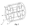
- Fig. 2 is a similar diagrammatical perspective view of an exemplary tubular fuel cell assembly incorporating a thermal shield;
- Fig. 3 is a diagrammatical view of a fuel cell assembly illustrating placement of the thermal shield within the assembly container and the flow of coolant within the assembly;
- Fig. 4 is diagrammatical a cross sectional view of the fuel cell assembly of Fig. 3 illustrating the placement of the thermal shield within the container;
- Fig. 5 is a detail sectional view of section 5-5 of Fig 4 illustrating a first exemplary configuration of the thermal shield;
- Fig. 6 is a detail sectional view of section 5-5 of Fig. 4 illustrating a second exemplary configuration of the thermal shield;
- Fig. 7 is a detail sectional view of section 5-5 of Fig. 4 illustrating a third exemplary configuration of the thermal shield;
- Fig. 8 is a detail sectional view of section 5-5 of Fig. 4 illustrating a fourth exemplary configuration of the thermal shield;
- Fig. 9 is a diagrammatical elevation view of a fuel cell assembly incorporating an alternative tubular thermal shield design;
- Fig. 10 is a diagrammatical elevational view of the fuel cell assembly of Fig. 9;
- Fig. 11 is a diagrammatic view of a fuel cell assembly in accordance with a further exemplary embodiment in which coolant is separated form oxidant flowing through the fuel cell assembly; and
- Fig. 12 is a partially broken away exploded view of a portion of the fuel cell assembly of Fig. 11.
-
- Fuel cells, such as solid oxide fuel cells, have demonstrated a potential for high efficiency and low pollution in power generation. In general, a fuel cell is an energy conversion device that produces electricity, by electrochemically combining a fuel and an oxidant across an ionic conducting layer. Fuel cells may be stacked together either in series or in parallel to construct the fuel cell architecture, capable of producing a resultant electrical energy output. In an exemplary embodiment illustrated in Fig. 1, an exemplary
fuel cell assembly 10, such as a solid oxide fuel cell assembly, comprises a fuel cell 12 (which may be referred to as a stack or collection of cells or stacks) disposed within a pressurizedcontainer 14. Athermal shield 16 is disposed between thefuel cell 12 and thecontainer 14 to provide improved thermal management of heat flux generated by thefuel cell 12 during operation, as discussed in greater detail below. - In this first exemplary embodiment, the
fuel cell 12 comprises a single fuel cell having planar configuration, although multiple such cells may be provided in a single structure. In another exemplary embodiment illustrated in Fig. 2fuel cell assembly 10 comprises aset 38 of fuel cells. Theset 38 of fuel cells comprisesfuel cells 40 having tubular configuration. Thefuel cells - Referring specifically to the embodiment of Fig. 1, the
exemplary fuel cell 12 comprises ananodes 20 and 28, a cathode 24, anelectrolyte 22 interposed therebetween, an interconnect 26 which is in intimate contact with at least one of the anode 20, the cathode 24 and theelectrolyte 22. As illustrated in Fig. 1, an oxidant, such as air, is introduced into thefuel cell 12 through anoxidant inlet 30, and exits through anexhaust 32. Similarly, a fuel flow is introduced into the assembly, as indicated generally atreference numeral 34. The oxidant flows through a coolant channel defined between the inner wall of thecontainer 14 and thethermal shield 16, and is introduced into thefuel cell 12, as indicated generally atreference numeral 36 to provide oxidant to the cathode 24. - In the
exemplary fuel cell 12, such as the solid oxide fuel cell, oxygen ions (O2-) generated at the cathode 24 are transported across theelectrolyte 22 interposed between the anode 20 and the cathode 24. Thefuel 34, for example natural gas, is fed to the anode 20. Thefuel 34 at the anode 20 site reacts with oxygen ions (O2-) transported to the anode 20 across theelectrolyte 22. The oxygen ions (O2-) are de-ionized to release electrons to an external electric circuit (not shown). The electron flow thus produces direct current electricity across the external electric circuit. The electricity generation process produces certain exhaust gases and generates waste heat. The exhaust gases are exhausted throughoutlet 32. - It should be noted that, in practice, the routing of the fuel and oxidant might vary depending upon the fuel cell design and operation. For example, while in the embodiments shown a single exhaust accommodates the oxidant and fuel discharged, these exhaust streams may be separated in certain designs.
- It should also be noted that the present technique offers a number of possibilities for at least partially thermally shielding the container wall from heat generated by the fuel cell. In one set of embodiments, for example, one or more flow paths are defined between the container wall and the thermal shield, and a coolant is circulated though the paths to extract heat via convective heat transfer. In a presently contemplated embodiment, the coolant stream comprises at least part of the oxidant needed for operation of the fuel cell. All or part of the coolant may be circulated through the cell, or the coolant stream may be supplemented by additional flow, depending upon such factors as the heat load, the coolant inlet temperature, the mass flow rate of coolant, and the mass flow rate of oxidant. The use of oxidant as coolant also provides the advantage of preheating the oxidant for more efficient reaction within the fuel cell. Alternatively, a separate coolant, including gaseous, liquid or mixed phase coolants, may be employed and isolated from the oxidant stream, as described in greater detail below.
- In an exemplary embodiment, as illustrated in Fig. 3 and Fig. 4, the
fuel cell assembly 10 comprises afuel cell 12 disposed within acontainer 14 configured to be pressurized, and athermal shield 16 disposed between thefuel cell 12 and thecontainer 14. Within thecontainer 14, alower distribution passage 42 is formed to distributecoolant flow 46. Thethermal shield 16 is spaced from thefuel cell container 14 to form aperipheral flow path 44 therebetween in fluid communication with thedistribution passage 42. - The
coolant flow 46, which again in certain embodiments may comprise some or all of the needed oxidant, enters through theoxidant inlet 30 and flows through thelower distribution passage 42. Thecoolant flow 46 is then distributed in the lower distribution passage and enters aperipheral passage 44, as indicated generally atreference numeral 48. Where the coolant comprises oxidant, preheated by energy extracted from thethermal shield 16 andcontainer 14 wall, at least a portion of thecoolant flow fuel cell 12, before being exhausted through theoutlet 32. - As shown in Fig. 5, in the illustrated embodiment the
thermal shield 16 presents aninner wall 54 disposed generally towards thefuel cell 12 and anouter wall 56 oriented towards the inner wall orperiphery 58 of thecontainer 14. In this embodiment, thethermal shield 16 is configured to substantially surround aninner volume 60 within which thefuel cell 12 is disposed, and to similarly contiguously circumscribes the inner wall orperiphery 58 of thecontainer 14 to provide for lowering the operating temperature of thecontainer 14 and to provide more uniform heat distribution around theinner periphery 58 of thecontainer 14. As further illustrated in Fig. 5, the peripheral passage or flowpath 44 is defined by the thermal shieldouter surface 56 and containerinner surface 58. - The
thermal shield 16 may comprise a thermally conductive material such as a metallic material. Thethermal shield 16 and the coolant flow through theflow path 44, maintain temperatures of thefuel cell container 14 at or below prescribed limits. Maintaining temperature of thefuel cell container 14 at or below prescribed limits aids in maintaining structural integrity of thefuel cell container 14, which may be fabricated from conventionally available and economically affordable materials which can nevertheless withstand the operating temperature range, such as between about 600 °C to about 1300 °C. In actual implementation, it is anticipated that the container will ideally operate at temperatures well below those of the fuel cell assembly, such as below the 600 °C to 1300 °C temperature range indicated. - In an alternative embodiment, illustrated in Fig. 6, the
thermal shield 16 includes an insulatinglayer 62 on theinner surface 54 of thethermal shield 16. In other embodiment, illustrated in Fig. 7, thecontainer 14 has another insulatinglayer 66 disposed on theinner surface 58 of thecontainer 14. The insulating layers 62 and 66 comprise an insulating material, which may include, but is not limited to, a ceramic coating such as plasma sprayed thermal barrier coating. Such coatings may include, for example, yttria stabilized zirconia oxides, porous or cellular ceramic foam materials, or other ceramics or low thermal conductivity metallic oxides capable of operating at the temperatures anticipated in the fuel cell assembly. The insulating layers 62, 66 maintain a desired thermal gradient through thethermal shield 16 andwall 58 of thecontainer 14 so as to reduce the temperature of the container wall during operation. Moreover, thethermal shield 16 effectively avoids or reduces thermal hot spots at localized regions in thecontainer 14 ensuring uniform structural integrity throughout thecontainer 14 surface. - In another embodiment, illustrated in Fig. 8, the
thermal shield 16 further comprises asecond shield wall 70 configured to define aninner surface 58 of thecontainer 14. In a further embodiment, the insulatinglayer 66 is disposed between thesecond shield wall 70 and theinner surface 58 of thecontainer 14. Theflow path 44 is defined by theinner surface 72 of thesecond shield wall 70 and theouter surface 56 of thethermal shield 16. This embodiment permits construction of thethermal shield 16 as a double-walled canister or vessel, which can simply be disposed within thecontainer 14 intermediate thecontainer wall 58 and thefuel cell 12. - In another embodiment, illustrated in Fig. 9 and Fig. 10, the
thermal shield 16 comprisesfluid distribution manifolds fluid conduits 80 configured to receive the cooling fluid therethrough. The plurality offluid conduits 80 receive and return circulating coolant by cooperation with passages within thefluid distribution manifolds manifolds fuel cell assembly 10. It should be noted, however, that the basic structure of this embodiment shares characteristics with the other embodiments described herein, such as substantially surrounding thefuel cell 12 and providing generally continuous shielding of the container wall. - Other embodiments may be envisaged that provide such improved thermal shielding, but sealingly isolate the coolant stream from the oxidant used by the cell. In one such embodiment, illustrated in Fig. 11 and Fig. 12, the cooling fluid enters the
container 14 through a coolingfluid inlet 88. The cooling fluid is exhausted through a coolingfluid outlet 90. Theoxidant 30 enters through anoxidant inlet 84 and is exhausted through anoxidant outlet 86. In such embodiments, the cooling fluid may include any suitable fluid, such as water, steam, a mixture thereof, or other fluids having desirable cooling properties (e.g. relatively high specific heat values). According to this embodiment, the thermal shield may comprise acylindrical shield assembly 82. Thecylindrical shield assembly 82 separates oxidant flow, received throughinlet 84 and exhausted throughoutlet 86, from coolant, which is received throughcoolant inlet 88 and exits throughcoolant outlet 90. In an exemplary construction, thecylindrical shield assembly 82 further comprises a base 92 having anannular groove 94 for receiving aseal 96. Thebase 92 supports alower edge 100 of thecylindrical shield 98. Theseal 96 fits within anannular groove 94 and separates the cooling fluid from the oxidant. Other construction techniques may, of course, be envisaged, such as for joining thebase 92 and thecylindrical shield 98 by welding, soldering, and so forth. - While only certain features of the invention have been illustrated and described herein, many modifications and changes will occur to those skilled in the art. It is, therefore, to be understood that the appended claims are intended to cover all such modifications and changes as fall within the true spirit of the invention. For example, features may be provided on the outer surface of the thermal shield to further enhance heat transfer from the thermal shield. Thus, where the thermal shield is made of a thermally conductive material, such as a metal, fins or other features may be provided that offer greater surface areas for heat transfer, increase or orient flow of coolant over the surfaces, or increase residence time of the coolant in the structure. Similarly, such structures may be provided separately from the thermal shield itself and disposed within the coolant passage, or affixed to the thermal shield during assembly.
- For the sake of good order, various aspects of the invention are set out in the following clauses:-
- 1. A fuel cell assembly (10) comprising:
- a container (14) configured to be pressurized;
- a fuel cell (12)disposed in the container (14); and
- a thermal shield (16) disposed between the container (14) and the fuel cell (12) and spaced from the container (14) to form a flow path (44) therebetween for a cooling fluid.
- 2. The fuel cell assembly (10) of clause 1, wherein the fuel cell (12) is selected from the group consisting of solid oxide fuel cells, proton exchange membrane fuel cells, molten carbonate fuel cells, phosphoric acid fuel cells, alkaline fuel cells, direct methanol fuel cells, regenerative fuel cells, zinc air fuel cells, and protonic ceramic fuel cells.
- 3. The fuel cell assembly (10) of clause 1, wherein the fuel cell (12) comprises at least one fuel cell (12) having planar configuration.
- 4. The fuel cell assembly (10) of clause 1, wherein the fuel cell (12) comprises at least one fuel cell (12) having tubular configuration (40).
- 5. The fuel cell assembly (10) of clause 1, wherein the thermal shield (16) is configured to define an insulating layer (62) on an inner surface (54) of the thermal shield (16).
- 6. The fuel cell assembly (10) of clause 5, wherein the thermal shield (16) is configured to define another insulating layer (66) on an inner surface (58) of the container (14).
- 7. The fuel cell assembly (10) of clause 6, wherein the insulating layer (62, 66) comprises an insulating material selected from the group consisting of ceramic oxides, cellular ceramic foam materials, and a combination thereof.
- 8. The fuel cell assembly (10) of clause 1, wherein the thermal shield (16) further comprises a second shield wall (70) configured to define an inner surface (58) of the container (14).
- 9. The fuel cell assembly (10) of clause 8, wherein the insulating layer (66) is disposed between the second shield wall (70) and the inner surface (58) of the container (14).
- 10. The fuel cell assembly (10) of clause 1, wherein the thermal shield (16) comprises a plurality of fluid conduits (80) configured to flow the cooling fluid (46) therethrough.
- 11. The fuel cell assembly (10) of
clause 10, wherein the plurality of fluid conduits (80) further comprises at least one fluid distribution manifold (76,78) configured to distribute the cooling fluid therethrough. - 12. The fuel cell assembly (10) of clause 11, wherein the cooling fluid comprises an oxidant.
- 13. The fuel cell assembly (10) of clause 1, wherein the thermal shield (16) comprises a cylindrical shield assembly (82).
- 14. The fuel cell assembly (10) of clause 13, wherein the cylindrical shield assembly (82) further comprises a base (92) and a seal (96) configured to separate the cooling fluid from the oxidant; the base (92) being configured to receive the seal (96).
- 15. A fuel cell assembly (10) comprising:
- a container (14) configured to be pressurized;
- a fuel cell (12) disposed in the container (14); and
- a metallic shield (16) disposed between the container (14) and the fuel cell (12) and spaced from the container (14) to form a flow path (44) therebetween for a cooling fluid.
- 16. The fuel cell assembly (10) of
clause 15, wherein the metallic shield (16) is configured to define an insulating layer (62) on an inner surface (54) of the metallic shield (16). - 17. The fuel cell assembly (10) of
clause 16, wherein the metallic shield (16) is configured to define another insulating layer (66) on an inner surface (58) of the container (14). - 18. The fuel cell assembly (10) of clause 17, wherein the insulating layer (62, 66) comprises an insulating material selected from the group consisting of ceramic oxides, cellular ceramic foam materials, and a combination thereof.
- 19. The fuel cell assembly (10) of
clause 15, wherein the metallic shield (16) further comprises a second shield wall (70) configured to define an inner surface (58) of the container (14). - 20. The fuel cell assembly (10) of clause 19, wherein the insulating layer (66) is disposed between the second shield wall (70) and the inner surface (58) of the container (14).
- 21. The fuel cell assembly (10) of
clause 15, wherein the cooling fluid (46) comprises an oxidant. - 22. A fuel cell assembly (10) comprising:
- a container (14) configured to be pressurized;
- a fuel cell (12) disposed in the container (14); and
- a shield (16) substantially surrounding a perimeter of the fuel cell; the shield (16) being disposed between the container (14) and the fuel cell (12) and spaced from the container (14) to form a flow path (44) therebetween for a cooling fluid.
- 23. The fuel cell assembly (10) of
clause 22, wherein the shield (16) substantially surrounding a perimeter of the fuel cell (12) is configured to substantially surround an inner periphery (58) of the container (14) to provide generally uniform thermal shielding around the fuel cell (12). - 24. The fuel cell assembly (10) of
clause 22, wherein the shield (16) substantially surrounding a perimeter of the fuel cell (12) comprises a thermally conductive material. - 25. The fuel cell assembly (10) of
clause 22, wherein the shield (16) is configured to define an insulating layer (62) on an inner surface (54) of the shield (16). - 26. The fuel cell assembly (10) of clause 25, wherein the shield (16) is configured to define another insulating layer (66) on an inner surface (58) of the container (14).
- 27. The fuel cell assembly (10) of clause 26, wherein the insulating layer (62, 66) comprises an insulating material selected from the group consisting of ceramic oxides, cellular ceramic foam materials, and a combination thereof.
- 28. The fuel cell assembly (10) of
clause 22, wherein the shield (16) further comprises a second shield wall (70) configured to define an inner surface (58) of the container (14). - 29. The fuel cell assembly (10) of
clause 28, wherein the insulating layer (66) is disposed between the second shield wall (70) and the inner surface (58) of the container (14). - 30. A fuel cell assembly (10) comprising:
- a container (14) configured to be pressurized;
- a fuel cell (12) disposed in the container (14); and
- a shield (16) substantially surrounding an inner periphery (58) of the container (14) to provide generally uniform thermal shielding around the fuel cell (12); the shield (16) being disposed between the container (14) and the fuel cell (12) and spaced from the container (14) to form a flow path (44) therebetween for a cooling fluid (46).
- 31. The fuel cell assembly (10) of
clause 30, wherein the shield (16) substantially surrounding an inner periphery (58) of the container (14) comprises a thermally conductive material. - 32. The fuel cell assembly (10) of
clause 30, wherein the shield (16) substantially surrounding an inner periphery (58) of the container (14) is configured to substantially surround a perimeter of the fuel cell (12). - 33. The fuel cell assembly (10) of
clause 30, wherein the shield (16) is configured to define an insulating layer (62) on an inner surface (54) of the shield (16). - 34. The fuel cell assembly (10) of clause 33, wherein the shield (16) is configured to define another insulating layer (66) on an inner surface (58) of the container (14).
- 35. The fuel cell assembly (10) of
clause 34, wherein the insulating layer (62, 66) comprises an insulating material selected from the group consisting of ceramic oxides, cellular ceramic foam materials, and a combination thereof. - 36. The fuel cell assembly (10) of
clause 30, wherein the shield (16) further comprises a second shield wall (70) configured to define an inner surface (58) of the container (14). - 37. The fuel cell assembly (10) of
clause 36, wherein the insulating layer (66) is disposed between the second shield wall (70) and the inner surface (58) of the container (14). - 38. A fuel cell assembly (10) comprising:
- a container (14) configured to be pressurized;
- a fuel cell (12) disposed in the container (14); and
- a thermally conductive shield (16) disposed between the container (14) and the fuel cell (12) and spaced from the container (14) to form a flow path (44) therebetween for a cooling fluid.
- 39. The fuel cell assembly (10) of
clause 38, wherein the thermally conductive shield (16) comprises a metallic material. - 40. The fuel cell assembly (10) of
clause 38, wherein the thermally conductive shield (16) is configured to substantially surround a perimeter of the fuel cell (12). - 41. The fuel cell assembly (10) of
clause 38, wherein the thermally conductive shield (16) is configured to substantially surround an inner periphery (58) of the container (14) to provide generally uniform thermal shielding around the fuel cell (12). - 42. The fuel cell assembly (10) of
clause 38, wherein the thermally conductive shield (16) is configured to define an insulating layer (62) on an inner surface (54) of the thermally conductive shield (16). - 43. The fuel cell assembly (10) of
clause 42, wherein the thermally conductive shield (16) is configured to define another insulating layer (66) on an inner surface (58) of the container (14). - 44. The fuel cell assembly (10) of clause 43, wherein the insulating layer (62, 66) comprises an insulating material selected from the group consisting of ceramic oxides, cellular ceramic foam materials, and a combination thereof.
- 45. The fuel cell assembly (10) of
clause 38, wherein the thermally conductive shield (16) further comprises a second shield wall (70) configured to define an inner surface (58) of the container (14). - 46. The fuel cell assembly (10) of clause 45, wherein the insulating layer (66) is disposed between the second shield wall (70) and the inner surface (58) of the container (14).
-
Claims (10)
- A fuel cell assembly (10) comprising:a container (14) configured to be pressurized;a fuel cell (12)disposed in the container (14); anda thermal shield (16) disposed between the container (14) and the fuel cell (12) and spaced from the container (14) to form a flow path (44) therebetween for a cooling fluid.
- The fuel cell assembly (10) of claim 1, wherein the fuel cell (12) is selected from the group consisting of solid oxide fuel cells, proton exchange membrane fuel cells, molten carbonate fuel cells, phosphoric acid fuel cells, alkaline fuel cells, direct methanol fuel cells, regenerative fuel cells, zinc air fuel cells, and protonic ceramic fuel cells.
- A fuel cell assembly (10) comprising:a container (14) configured to be pressurized;a fuel cell (12) disposed in the container (14); anda metallic shield (16) disposed between the container (14) and the fuel cell (12) and spaced from the container (14) to form a flow path (44) therebetween for a cooling fluid.
- The fuel cell assembly (10) of claim 3, wherein the metallic shield (16) is configured to define an insulating layer (62) on an inner surface (54) of the metallic shield (16).
- A fuel cell assembly (10) comprising:a container (14) configured to be pressurized;a fuel cell (12) disposed in the container (14); anda shield (16) substantially surrounding a perimeter of the fuel cell; the shield (16) being disposed between the container (14) and the fuel cell (12) and spaced from the container (14) to form a flow path (44) therebetween for a cooling fluid.
- The fuel cell assembly (10) of claim 5, wherein the shield (16) substantially surrounding a perimeter of the fuel cell (12) is configured to substantially surround an inner periphery (58) of the container (14) to provide generally uniform thermal shielding around the fuel cell (12).
- A fuel cell assembly (10) comprising:a container (14) configured to be pressurized;a fuel cell (12) disposed in the container (14); anda shield (16) substantially surrounding an inner periphery (58) of the container (14) to provide generally uniform thermal shielding around the fuel cell (12); the shield (16) being disposed between the container (14) and the fuel cell (12) and spaced from the container (14) to form a flow path (44) therebetween for a cooling fluid (46).
- The fuel cell assembly (10) of claim 7, wherein the shield (16) substantially surrounding an inner periphery (58) of the container (14) comprises a thermally conductive material.
- A fuel cell assembly (10) comprising:a container (14) configured to be pressurized;a fuel cell (12) disposed in the container (14); anda thermally conductive shield (16) disposed between the container (14) and the fuel cell (12) and spaced from the container (14) to form a flow path (44) therebetween for a cooling fluid.
- The fuel cell assembly (10) of claim 9, wherein the thermally conductive shield (16) comprises a metallic material.
Applications Claiming Priority (2)
| Application Number | Priority Date | Filing Date | Title |
|---|---|---|---|
| US10/305,162 US6896987B2 (en) | 2002-11-27 | 2002-11-27 | Fuel cell container cooling system |
| US305162 | 2002-11-27 |
Publications (1)
| Publication Number | Publication Date |
|---|---|
| EP1427045A2 true EP1427045A2 (en) | 2004-06-09 |
Family
ID=32312180
Family Applications (1)
| Application Number | Title | Priority Date | Filing Date |
|---|---|---|---|
| EP03257437A Withdrawn EP1427045A2 (en) | 2002-11-27 | 2003-11-26 | Fuel cell container cooling system |
Country Status (5)
| Country | Link |
|---|---|
| US (1) | US6896987B2 (en) |
| EP (1) | EP1427045A2 (en) |
| JP (1) | JP2004179166A (en) |
| CN (1) | CN1507100A (en) |
| CA (1) | CA2449261A1 (en) |
Cited By (1)
| Publication number | Priority date | Publication date | Assignee | Title |
|---|---|---|---|---|
| US8241813B2 (en) | 2005-04-05 | 2012-08-14 | Rolls-Royce Plc | Fuel cell arrangement |
Families Citing this family (11)
| Publication number | Priority date | Publication date | Assignee | Title |
|---|---|---|---|---|
| KR101049830B1 (en) * | 2004-04-21 | 2011-07-15 | 삼성에스디아이 주식회사 | Fuel cell system |
| JP4958080B2 (en) * | 2005-03-11 | 2012-06-20 | 一般財団法人電力中央研究所 | Fuel cell with heat shield container |
| JP2007134178A (en) * | 2005-11-10 | 2007-05-31 | Toyota Motor Corp | Tube type fuel cell module |
| US20070185216A1 (en) | 2006-02-09 | 2007-08-09 | Marcia Snyder | Antiviral method |
| US20080276631A1 (en) * | 2007-05-07 | 2008-11-13 | Ajith Kuttannair Kumar | System and Method for Cooling a Battery |
| JP5309139B2 (en) * | 2007-08-20 | 2013-10-09 | マイ エフシー エイビー | Arrangement for interconnecting electrochemical cells, fuel cell assembly, and method of manufacturing a fuel cell device |
| JP5334513B2 (en) * | 2008-09-25 | 2013-11-06 | 京セラ株式会社 | Fuel cell module and fuel cell device |
| US20100285386A1 (en) * | 2009-05-08 | 2010-11-11 | Treadstone Technologies, Inc. | High power fuel stacks using metal separator plates |
| JP5645375B2 (en) * | 2009-07-17 | 2014-12-24 | 三菱重工業株式会社 | Combined power generation system |
| DE102013200790A1 (en) * | 2013-01-18 | 2014-07-24 | Robert Bosch Gmbh | Cooling system with a coolant-flowed heat sink for cooling a battery |
| JP6331970B2 (en) * | 2014-10-30 | 2018-05-30 | 株式会社デンソー | Fuel cell device |
Family Cites Families (4)
| Publication number | Priority date | Publication date | Assignee | Title |
|---|---|---|---|---|
| US5952116A (en) * | 1995-02-16 | 1999-09-14 | Siemens Aktiengesellschaft | Solid electrolyte high temperature fuel cell module and method for its operation |
| US5750278A (en) * | 1995-08-10 | 1998-05-12 | Westinghouse Electric Corporation | Self-cooling mono-container fuel cell generators and power plants using an array of such generators |
| DE10040792C2 (en) * | 2000-08-21 | 2003-04-10 | Proton Motor Fuel Cell Gmbh | Polymer electrolyte membrane fuel cell system with cooling medium distribution space and collecting space and with cooling by fluid media |
| US20030054215A1 (en) * | 2001-09-20 | 2003-03-20 | Honeywell International, Inc. | Compact integrated solid oxide fuel cell system |
-
2002
- 2002-11-27 US US10/305,162 patent/US6896987B2/en not_active Expired - Fee Related
-
2003
- 2003-11-13 CA CA002449261A patent/CA2449261A1/en not_active Abandoned
- 2003-11-26 EP EP03257437A patent/EP1427045A2/en not_active Withdrawn
- 2003-11-27 JP JP2003396594A patent/JP2004179166A/en active Pending
- 2003-11-27 CN CNA2003101196618A patent/CN1507100A/en active Pending
Cited By (1)
| Publication number | Priority date | Publication date | Assignee | Title |
|---|---|---|---|---|
| US8241813B2 (en) | 2005-04-05 | 2012-08-14 | Rolls-Royce Plc | Fuel cell arrangement |
Also Published As
| Publication number | Publication date |
|---|---|
| US6896987B2 (en) | 2005-05-24 |
| CA2449261A1 (en) | 2004-05-27 |
| JP2004179166A (en) | 2004-06-24 |
| US20040101726A1 (en) | 2004-05-27 |
| CN1507100A (en) | 2004-06-23 |
Similar Documents
| Publication | Publication Date | Title |
|---|---|---|
| US6146779A (en) | Fluid flow plate, fuel cell assembly system, and method employing same for controlling heat in fuel cells | |
| US7329471B2 (en) | Methods and apparatus for assembling solid oxide fuel cells | |
| KR20030076259A (en) | A fuel cell battery with an integrated heat exchanger | |
| EP4135082B1 (en) | Fuel plenum and fuel cell stack including same | |
| US6756144B2 (en) | Integrated recuperation loop in fuel cell stack | |
| US20070003806A1 (en) | Heat exchanger for fuel cell stack | |
| US6896987B2 (en) | Fuel cell container cooling system | |
| CN102047481A (en) | Solid oxide fuel cell systems | |
| US11764389B2 (en) | Fuel cell manifold having an embedded dielectric layer and methods of making thereof | |
| US8021794B2 (en) | Fuel cell with cross-shaped reformer | |
| JP5122319B2 (en) | Solid oxide fuel cell | |
| JP2004139960A (en) | Fuel cell | |
| US9444117B2 (en) | Proton exchange membrane fuel cell with open pore cellular foam | |
| US8808940B2 (en) | Solid oxide fuel cell with sealed structure | |
| JP4544055B2 (en) | Fuel cell | |
| US20250062369A1 (en) | Interconnect for a fuel cell stack and method of operating the stack | |
| US12341224B2 (en) | Fuel cell stack assembly including heat sink inserts | |
| JP2007005134A (en) | Steam generator and fuel cell | |
| JP2010238440A (en) | Fuel cell module | |
| JP2025097628A (en) | Electrochemical stack, hot module, and hydrogen production apparatus | |
| CA3181279A1 (en) | Fuel cell stack assembly including heat sink inserts | |
| JPS61148768A (en) | Fused carbonate type fuel cell | |
| JPH0589895A (en) | Solid oxide fuel cell | |
| JPS61148767A (en) | Fused carbonate type fuel cell |
Legal Events
| Date | Code | Title | Description |
|---|---|---|---|
| PUAI | Public reference made under article 153(3) epc to a published international application that has entered the european phase |
Free format text: ORIGINAL CODE: 0009012 |
|
| AK | Designated contracting states |
Kind code of ref document: A2 Designated state(s): AT BE BG CH CY CZ DE DK EE ES FI FR GB GR HU IE IT LI LU MC NL PT RO SE SI SK TR |
|
| AX | Request for extension of the european patent |
Extension state: AL LT LV MK |
|
| STAA | Information on the status of an ep patent application or granted ep patent |
Free format text: STATUS: THE APPLICATION IS DEEMED TO BE WITHDRAWN |
|
| 18D | Application deemed to be withdrawn |
Effective date: 20080602 |