EP1426990A2 - Lighted switch device - Google Patents
Lighted switch device Download PDFInfo
- Publication number
- EP1426990A2 EP1426990A2 EP03027722A EP03027722A EP1426990A2 EP 1426990 A2 EP1426990 A2 EP 1426990A2 EP 03027722 A EP03027722 A EP 03027722A EP 03027722 A EP03027722 A EP 03027722A EP 1426990 A2 EP1426990 A2 EP 1426990A2
- Authority
- EP
- European Patent Office
- Prior art keywords
- light
- knobs
- knob
- push
- operating
- Prior art date
- Legal status (The legal status is an assumption and is not a legal conclusion. Google has not performed a legal analysis and makes no representation as to the accuracy of the status listed.)
- Granted
Links
Images



Classifications
-
- H—ELECTRICITY
- H01—ELECTRIC ELEMENTS
- H01H—ELECTRIC SWITCHES; RELAYS; SELECTORS; EMERGENCY PROTECTIVE DEVICES
- H01H19/00—Switches operated by an operating part which is rotatable about a longitudinal axis thereof and which is acted upon directly by a solid body external to the switch, e.g. by a hand
- H01H19/02—Details
- H01H19/025—Light-emitting indicators
-
- H—ELECTRICITY
- H01—ELECTRIC ELEMENTS
- H01H—ELECTRIC SWITCHES; RELAYS; SELECTORS; EMERGENCY PROTECTIVE DEVICES
- H01H2219/00—Legends
- H01H2219/054—Optical elements
- H01H2219/062—Light conductor
-
- H—ELECTRICITY
- H01—ELECTRIC ELEMENTS
- H01H—ELECTRIC SWITCHES; RELAYS; SELECTORS; EMERGENCY PROTECTIVE DEVICES
- H01H2219/00—Legends
- H01H2219/054—Optical elements
- H01H2219/062—Light conductor
- H01H2219/0622—Light conductor only an illuminated ring around keys
Definitions
- the present invention relates to a lighted switch device used in, for example, a control section of a vehicle-installed air conditioner, and, more particularly, to means for preventing undesirable leakage of light from some portion.
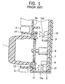
- a related lighted switch device for a vehicle-installed air conditioner comprises one rotary knob (first operating knob) 1, four push knobs (second operating knobs) 2, 3, 4, and 5 disposed around the rotary knob 1, a case 6 having a front plate 6a to which the rotary knob 1 and the push knobs 2, 3, 4, and 5 are mounted, a rotation detector 8 mounted to a wiring board 7 and accommodated in the case 6, switch elements 9, LEDs 10 (light-emitting diodes serving as light sources), and an annular light conductor 11 for transmitting exiting light 10a from the LEDs 10 to the outer peripheral portion of the rotary knob 1.
- This type of related lighted switch device further comprises an annular light-shielding member 13, disposed at a portion of the case 6 where the light conductor 11 is disposed, for preventing light from leaking into gaps 12 formed between pairs of adjacent push knobs, that is, between the push knobs 2 and 3, between the push knobs 3 and 4, between the push knobs 4 and 5, and between the push knobs 5 and 2.
- the annular light-shielding member 13 is disposed around the annular light conductor 11, it is possible to prevent light from leaking into the gaps 12, disposed between the respective pairs of adjacent push knobs, from the light conductor 11, so that the lighted switch device can be easily seen.
- the related lighted switch device since the light-shielding member 13, which is formed at the case 6, is disposed in a gap 14 between the rotary knob 1 and the,push knobs 2 to 5, the light-shielding member 13 is viewed concentrically with the light conductor 11 in plan view of the lighted switch device. Therefore, the related lighted switch device is not designed well. In addition, the gap 14 is inevitably large. Therefore, also for this reason, the related lighted switch device is not designed well, thereby increasing the size of the switch device. Further, since the light-shielding member 13 is formed at the case 6, a die used for injection molding of the case 6 is large and complicated. Therefore, the lighted switch device, which is a product, is high in cost.
- the present invention is achieved to overcome the aforementioned related problems, and has as its object the provision of a small low-cost lighted switch device which is designed well.
- a lighted switch device comprising a first operating knob; a plurality of second operating knobs comprising a pair of adjacent second operating knobs and disposed around the first operating knob; a case having a front plate for mounting the first operating knob and the plurality of second operating knobs; a light source accommodated in the case; a light conductor for transmitting exiting light from the light source to an outer peripheral portion of the first operating knob; and a light-shielding member, which is disposed at one of the pair of adjacent second operating knobs and which protrudes in a gap disposed between the pair of adjacent second operating knobs, for preventing light from leaking into the gap from the light conductor.
- the size of the gap is small, which is, in general, approximately 1 mm. Therefore, the light-shielding member is only slightly seen in plan view of the lighted switch device, so that the design of the lighted switch device can be improved. In addition, it is not necessary to form the light-shielding member at the case, and a gap between the first operating knob and the second operating knobs can be reduced in size.
- the design of the lighted switch device can be improved, thereby reducing the size of the lighted switch device. Further, since it is not necessary to form the light-shielding member at the case, it is possible to simplify and reduce the size of a die used for injection molding of the case, and, thus, to reduce the cost of the lighted switch device, which is a product.
- the other of the pair of second operating knobs has a recess for inserting an end of the light-shielding member.
- the first operating knob may be a rotary knob
- the plurality of second operating knobs may be push knobs
- the first operating knob is a rotary knob
- the second operating knobs are push knobs
- the operability of the switch device can be enhanced.
- the push knobs are used for selecting functions, such as automatic-manual switching of a vehicle-installed air conditioner, in-vehicle-defrosting switching, temperature setting, and air volume setting
- the rotary knob is used for temperature adjustment and air volume adjustment
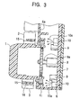
- the lighted switch device of the embodiment has basically the same structure as the related lighted switch device. It comprises one rotary knob (first operating knob) 1, four push knobs (second operating knobs) 2, 3, 4, and 5 disposed around the rotary knob 1, a case 6 having a front plate 6a to which the rotary knob 1 and the push knobs 2, 3, 4, and 5 are mounted, a rotation detector 8 mounted to a wiring board 7 and accommodated in the case 6, switch elements 9, LEDs 10 (light-emitting diodes serving as light sources), and an annular light conductor 11 for transmitting exiting light 10a from the LEDs 10 to the outer peripheral portion of the rotary knob 1.
- the rotary knob 1 is injection molded out of resin and into the shape of a cap including a top surface 1a and a cylindrical portion 1b, and is rotatably mounted to the front plate 6a of the case 6.
- a character, a pictorial character, etc. which is illuminated by the exiting light 10a from the LEDs 10, may be indicated on the top surface 1a of the rotary knob 1.
- the push knobs 2, 3, 4, and 5 are injection molded out of resin and into the shape of a tray, and are mounted to the front plate 6a of the case 6 so that they can be pushed.
- the push knob 2 has a push surface 2a and a flange 2b.
- the push knob 3 has a push surface 3a and a flange 3b.
- the push knob 4 has a push surface 4a and a flange 4b.
- the push knob 5 has a push surface 5a and a flange 5b. As shown in Fig.
- plate-shaped light-shielding members 15 vertically protrude from a surface of the push knob 2 opposing the push knob 3, a surface of the push knob 2 opposing the push knob 5, a surface of the push knob 4 opposing the push knob 3, and a surface of the push knob 4 opposing the push knob 5, respectively.
- Recesses 16 into which ends of the light-shielding members 15 are inserted are formed in portions of the push knob 3 opposing the respective light-shielding members 15 and portions of the push knob 5 opposing the respective light-shielding members 15. As shown in Fig. 1, when the ends of the respective light-shielding members 15 are inserted into the respective recesses 16, the push knobs 2, 3, 4, and 5 are disposed close to each other and to the rotary knob 1.
- the case 6 is injection molded out of resin and into the shape of a box so that the case 6 can accommodate the wiring board 7, the rotation detector 8, the switch elements 9, the LEDs 10, and the light conductor 11.
- the rotation detector 8 may be, for example, a rotary variable resistor or a rotary encoder. Its rotary shaft 8a is connected to the rotary knob 1 through a required power transmission device such as a gear mechanism.
- the switch elements 9 each comprise a tactile switch and a click rubber disposed on the wiring board 7, and have a contact that is brought into electrical conduction with the wiring board and the click rubber by bending the click rubber.
- the switch elements 9 are disposed at portions opposing the central portions of the respective push knobs 2, 3, 4, and 5.
- the switch elements 9 can be directly operated by the respective push knobs 2, 3, 4, and 5, or indirectly operated through a coupling member (not shown), which is called an actuator.
- the LEDs 10 are disposed at equal intervals around the light conductor 11.
- the light conductor 11 is formed of a light-transmissive resin material and into an annular shape. As shown in Fig. 3, the light conductor 11 is disposed around a portion of the case 6 where the rotary knob 1 is disposed.
- the lighted switch device of the embodiment comprises one rotary knob 1 and four push knobs 2, 3, 4, and 5, when any of the push knobs 2, 3, 4, and 5 are used for selecting functions, such as automatic-manual switching of a vehicle-installed air conditioner, in-vehicle-defrosting switching, temperature setting, and air volume setting, and when the rotary knob 1 is used for temperature adjustment and air volume adjustment, it is possible to match the operational feel of the knobs 1 to 5 and the feel of selecting the respective functions and adjusting the functions. Therefore, the lighted switch device, which is used in a control section of the vehicle-installed air conditioner, provides good operational feel.
- the plate-shaped light-shielding members 15 protrude from a surface of the push knob 2 opposing the push knob 3, a surface of the push knob 2 opposing the push knob 5, a surface of the push knob 4 opposing the push knob 3, and a surface of the push knob 4 opposing the push knob 5, respectively.
- the recesses 16 into which ends of the light-shielding members 15 are inserted are formed in portions of the push knob 3 opposing the respective light-shielding members 15 and portions of the push knob 5 opposing the respective light-shielding members 15. Therefore, the light-shielding members 15 only slightly appear at the surface of the lighted switch device, so that the design of the lighted switch device can be improved.
- each gap 12 between its associated pair of adjacent push knobs is completely closed by its associated light-shielding member 15, it is possible to prevent light from leaking into the gaps 12, so that the rotary knob 1 can be seen well.
- a gap 14 between the rotary knob 1 and the push knobs 2, 3, 4, and 5 can be reduced in size, so that, also for this reason, the design of the lighted switch device can be improved, as a result of which the lighted switch device can be reduced in size.
- it is not necessary to form the light-shielding members at the case 6, it is possible to simplify and reduce the size of a die used for injection molding of the case 6, and, thus, to reduce the cost of the lighted switch device, which is a product.
- the rotary knob 1 is used as a first operating knob and the push knobs 2, 3, 4, and 5 are used as second operating knobs
- the gist of the present invention is not limited thereto, so that push knobs may be used for the first operating knobs and the second operating knobs.
- the light-shielding members 15 are formed at the push knobs 2 and 4, and the recesses 16 are formed in the push knobs 3 and 5, the gist of the present invention is not limited thereto. Therefore, when the gaps 12 are shielded from light, it is possible to omit the recesses 16 formed in the push knobs 3 and 5.
- the gist of the present invention is not limited thereto. Therefore, the number of push knobs disposed around the rotary knob 1 may be changed as required depending upon the purpose of use of the lighted switch device.
Landscapes
- Switches With Compound Operations (AREA)
- Switch Cases, Indication, And Locking (AREA)
- Rotary Switch, Piano Key Switch, And Lever Switch (AREA)
- Push-Button Switches (AREA)
Abstract
Description
Claims (4)
- A lighted switch device comprising:a first operating knob;a pair of adjacent second operating knobs disposed adjacent to the periphery of the first operating knob;a case having a front plate for mounting the first operating knob and the second operating knobs;a light source accommodated in the case;a light conductor for transmitting exiting light from the light source to an outer peripheral portion of the first operating knob; anda light-shielding member, which is disposed at one of the pair of adjacent second operating knobs and which protrudes in a gap disposed between the pair of adjacent second operating knobs, for preventing light from leaking into the gap from the light conductor.
- A lighted switch device according to Claim 1, wherein the other of the pair of second operating knobs has a recess for inserting an end of the light-shielding member.
- A lighted switch device according to Claim 1 or 2, wherein the first operating knob is a rotary knob, and wherein the second operating knobs are push knobs.
- A lighted switch device according to any of Claims 1 to 3, wherein a plurality of second operating knobs is disposed around the first operating knob.
Applications Claiming Priority (2)
| Application Number | Priority Date | Filing Date | Title |
|---|---|---|---|
| JP2002351296A JP3970756B2 (en) | 2002-12-03 | 2002-12-03 | Illuminated switch device |
| JP2002351296 | 2002-12-03 |
Publications (3)
| Publication Number | Publication Date |
|---|---|
| EP1426990A2 true EP1426990A2 (en) | 2004-06-09 |
| EP1426990A3 EP1426990A3 (en) | 2004-11-17 |
| EP1426990B1 EP1426990B1 (en) | 2006-02-22 |
Family
ID=32310700
Family Applications (1)
| Application Number | Title | Priority Date | Filing Date |
|---|---|---|---|
| EP03027722A Expired - Lifetime EP1426990B1 (en) | 2002-12-03 | 2003-12-02 | Lighted switch device |
Country Status (4)
| Country | Link |
|---|---|
| US (1) | US7014330B2 (en) |
| EP (1) | EP1426990B1 (en) |
| JP (1) | JP3970756B2 (en) |
| DE (1) | DE60303637T2 (en) |
Cited By (3)
| Publication number | Priority date | Publication date | Assignee | Title |
|---|---|---|---|---|
| EP2211249A2 (en) | 2009-01-22 | 2010-07-28 | E.G.O. ELEKTRO-GERÄTEBAU GmbH | Operating device for an electric device and control panel |
| WO2012089506A1 (en) * | 2010-12-30 | 2012-07-05 | Arcelik Anonim Sirketi | Illuminated knob for household appliance |
| CN103384797A (en) * | 2010-12-31 | 2013-11-06 | 阿塞里克股份有限公司 | A household appliance comprising a knob the outer periphery of which is illuminated |
Families Citing this family (19)
| Publication number | Priority date | Publication date | Assignee | Title |
|---|---|---|---|---|
| US20060164397A1 (en) * | 2005-01-27 | 2006-07-27 | Maytag Corporation | Appliance with membrane overlay |
| US7105759B1 (en) * | 2005-06-28 | 2006-09-12 | Tektronix, Inc. | Instrument with illuminated control knob |
| TWM292711U (en) * | 2005-12-23 | 2006-06-21 | Micro Star Int Co Ltd | Knob structure |
| JP2010114010A (en) * | 2008-11-10 | 2010-05-20 | Shin Etsu Polymer Co Ltd | Lighting structure of mobile apparatus |
| TW201110174A (en) * | 2009-06-24 | 2011-03-16 | Fujikura Ltd | Sheet luminescent device and manufacturing method thereof |
| ES2376447B1 (en) * | 2010-01-08 | 2013-01-29 | Fagor, S. Coop. | ILLUMINABLE CONTROL DEVICE ADAPTED TO A CONTROL PANEL OF AN APPLIANCES. |
| US8813676B2 (en) | 2010-05-07 | 2014-08-26 | Whirlpool Corporation | User interface for a controller |
| EP2518592B1 (en) | 2011-04-25 | 2017-07-26 | Daesung Electric Co., Ltd | Haptic steering wheel switch apparatus |
| EP2518591B1 (en) | 2011-04-25 | 2018-05-30 | LS Automotive Technologies Co., Ltd. | Haptic steering wheel switch apparatus and haptic steering wheel switch system including the same |
| JP5994667B2 (en) * | 2013-02-08 | 2016-09-21 | 株式会社デンソー | Operating device |
| US20190052025A1 (en) * | 2015-09-14 | 2019-02-14 | Interlemo Holding S.A. | Smart active connector |
| KR102559885B1 (en) | 2015-12-30 | 2023-07-27 | 삼성전자주식회사 | Cooking appliance having switch assembly |
| USD868009S1 (en) | 2016-06-03 | 2019-11-26 | Lutron Technology Company Llc | Illuminated control device |
| USD868010S1 (en) | 2016-06-30 | 2019-11-26 | Lutron Technology Company Llc | Illuminated control device |
| KR102513487B1 (en) * | 2016-08-10 | 2023-03-23 | 삼성전자주식회사 | Cooking appliance |
| USD951211S1 (en) | 2017-03-16 | 2022-05-10 | Lutron Technology Company Llc | Illuminated control device |
| USD863237S1 (en) * | 2017-09-22 | 2019-10-15 | Whirlpool Corporation | Push button knob with illumination capabilities for a laundry treating appliance |
| KR102028840B1 (en) * | 2018-08-20 | 2019-10-04 | 김태준 | Operation switch assembly with waterproof structure |
| USD935422S1 (en) | 2019-05-01 | 2021-11-09 | Lutron Technology Company Llc | Control device having illumination applied thereto |
Family Cites Families (3)
| Publication number | Priority date | Publication date | Assignee | Title |
|---|---|---|---|---|
| DE19627212C2 (en) | 1996-07-05 | 1998-11-05 | Hella Kg Hueck & Co | Actuating unit for a vehicle component, in particular a vehicle air conditioning system |
| JP3576720B2 (en) * | 1996-10-15 | 2004-10-13 | 株式会社東海理化電機製作所 | Dial operating device |
| JP3693857B2 (en) | 1999-07-01 | 2005-09-14 | アルプス電気株式会社 | Illuminated switch unit |
-
2002
- 2002-12-03 JP JP2002351296A patent/JP3970756B2/en not_active Expired - Fee Related
-
2003
- 2003-12-02 EP EP03027722A patent/EP1426990B1/en not_active Expired - Lifetime
- 2003-12-02 DE DE60303637T patent/DE60303637T2/en not_active Expired - Lifetime
- 2003-12-02 US US10/726,407 patent/US7014330B2/en not_active Expired - Fee Related
Cited By (7)
| Publication number | Priority date | Publication date | Assignee | Title |
|---|---|---|---|---|
| EP2211249A2 (en) | 2009-01-22 | 2010-07-28 | E.G.O. ELEKTRO-GERÄTEBAU GmbH | Operating device for an electric device and control panel |
| EP2211249A3 (en) * | 2009-01-22 | 2010-08-18 | E.G.O. ELEKTRO-GERÄTEBAU GmbH | Operating device for an electric device and control panel |
| WO2012089506A1 (en) * | 2010-12-30 | 2012-07-05 | Arcelik Anonim Sirketi | Illuminated knob for household appliance |
| CN103403829A (en) * | 2010-12-30 | 2013-11-20 | 阿塞里克股份有限公司 | Illuminated knob for household appliance |
| CN103403829B (en) * | 2010-12-30 | 2015-11-25 | 阿塞里克股份有限公司 | For the illuminated adjuster of household electrical appliance |
| CN103384797A (en) * | 2010-12-31 | 2013-11-06 | 阿塞里克股份有限公司 | A household appliance comprising a knob the outer periphery of which is illuminated |
| CN103384797B (en) * | 2010-12-31 | 2016-04-13 | 阿塞里克股份有限公司 | Comprise the household electrical appliance of the adjuster that neighboring is illuminated |
Also Published As
| Publication number | Publication date |
|---|---|
| JP3970756B2 (en) | 2007-09-05 |
| DE60303637T2 (en) | 2006-12-21 |
| JP2004185976A (en) | 2004-07-02 |
| DE60303637D1 (en) | 2006-04-27 |
| US20040109304A1 (en) | 2004-06-10 |
| US7014330B2 (en) | 2006-03-21 |
| EP1426990B1 (en) | 2006-02-22 |
| EP1426990A3 (en) | 2004-11-17 |
Similar Documents
| Publication | Publication Date | Title |
|---|---|---|
| EP1426990B1 (en) | Lighted switch device | |
| US6310308B1 (en) | Compact push-button switch assembly | |
| US4710602A (en) | Illuminated rocker switch assembly | |
| EP1518726B1 (en) | Operating device of air conditioner for vehicle | |
| JP5508866B2 (en) | Operation device and control panel for electrical appliances | |
| US5892192A (en) | Operation device for vehicle air conditioner | |
| US8469529B2 (en) | Display device | |
| JP2005285736A (en) | Illumination device | |
| US7163455B2 (en) | Operating device for air conditioner for vehicle | |
| DE112010004640T5 (en) | Structure of an electric switch comprising a 5-way toogle mechanism and an illuminated, flexible layer | |
| US4710858A (en) | Panel displays, framed lighted switch actuators therefor | |
| US6777633B2 (en) | Switch device | |
| JP2007012609A (en) | Electronic equipment and knob | |
| JP6244331B2 (en) | Multi-directional switch device | |
| JP3649637B2 (en) | Illumination structure of electronic equipment | |
| JP2001155573A (en) | switch | |
| JP2001229779A (en) | Mounting structure of rotary electric part with illumination | |
| WO2015087366A1 (en) | Electronic component with moveable part | |
| JP2004186018A (en) | Multiple push switch | |
| JPH0726178Y2 (en) | Knob with display function | |
| JPH0455382Y2 (en) | ||
| JP3166073B2 (en) | Switch operation panel | |
| JP5299701B2 (en) | Operating device | |
| US10741343B2 (en) | Keypad device with rocker button mechanism | |
| JP2005259401A (en) | Push down type switch structure |
Legal Events
| Date | Code | Title | Description |
|---|---|---|---|
| PUAI | Public reference made under article 153(3) epc to a published international application that has entered the european phase |
Free format text: ORIGINAL CODE: 0009012 |
|
| AK | Designated contracting states |
Kind code of ref document: A2 Designated state(s): AT BE BG CH CY CZ DE DK EE ES FI FR GB GR HU IE IT LI LU MC NL PT RO SE SI SK TR |
|
| AX | Request for extension of the european patent |
Extension state: AL LT LV MK |
|
| PUAL | Search report despatched |
Free format text: ORIGINAL CODE: 0009013 |
|
| AK | Designated contracting states |
Kind code of ref document: A3 Designated state(s): AT BE BG CH CY CZ DE DK EE ES FI FR GB GR HU IE IT LI LU MC NL PT RO SE SI SK TR |
|
| AX | Request for extension of the european patent |
Extension state: AL LT LV MK |
|
| 17P | Request for examination filed |
Effective date: 20041130 |
|
| GRAP | Despatch of communication of intention to grant a patent |
Free format text: ORIGINAL CODE: EPIDOSNIGR1 |
|
| AKX | Designation fees paid |
Designated state(s): DE FR GB IT |
|
| GRAS | Grant fee paid |
Free format text: ORIGINAL CODE: EPIDOSNIGR3 |
|
| GRAA | (expected) grant |
Free format text: ORIGINAL CODE: 0009210 |
|
| AK | Designated contracting states |
Kind code of ref document: B1 Designated state(s): DE FR GB IT |
|
| REG | Reference to a national code |
Ref country code: GB Ref legal event code: FG4D |
|
| REF | Corresponds to: |
Ref document number: 60303637 Country of ref document: DE Date of ref document: 20060427 Kind code of ref document: P |
|
| PLBE | No opposition filed within time limit |
Free format text: ORIGINAL CODE: 0009261 |
|
| STAA | Information on the status of an ep patent application or granted ep patent |
Free format text: STATUS: NO OPPOSITION FILED WITHIN TIME LIMIT |
|
| 26N | No opposition filed |
Effective date: 20061123 |
|
| EN | Fr: translation not filed | ||
| PG25 | Lapsed in a contracting state [announced via postgrant information from national office to epo] |
Ref country code: FR Free format text: LAPSE BECAUSE OF FAILURE TO SUBMIT A TRANSLATION OF THE DESCRIPTION OR TO PAY THE FEE WITHIN THE PRESCRIBED TIME-LIMIT Effective date: 20070420 |
|
| GBPC | Gb: european patent ceased through non-payment of renewal fee |
Effective date: 20071202 |
|
| PG25 | Lapsed in a contracting state [announced via postgrant information from national office to epo] |
Ref country code: FR Free format text: LAPSE BECAUSE OF FAILURE TO SUBMIT A TRANSLATION OF THE DESCRIPTION OR TO PAY THE FEE WITHIN THE PRESCRIBED TIME-LIMIT Effective date: 20060222 |
|
| PG25 | Lapsed in a contracting state [announced via postgrant information from national office to epo] |
Ref country code: GB Free format text: LAPSE BECAUSE OF NON-PAYMENT OF DUE FEES Effective date: 20071202 |
|
| PGFP | Annual fee paid to national office [announced via postgrant information from national office to epo] |
Ref country code: IT Payment date: 20101211 Year of fee payment: 8 |
|
| PGFP | Annual fee paid to national office [announced via postgrant information from national office to epo] |
Ref country code: DE Payment date: 20111230 Year of fee payment: 9 |
|
| REG | Reference to a national code |
Ref country code: DE Ref legal event code: R119 Ref document number: 60303637 Country of ref document: DE Effective date: 20130702 |
|
| PG25 | Lapsed in a contracting state [announced via postgrant information from national office to epo] |
Ref country code: DE Free format text: LAPSE BECAUSE OF NON-PAYMENT OF DUE FEES Effective date: 20130702 |
|
| PG25 | Lapsed in a contracting state [announced via postgrant information from national office to epo] |
Ref country code: IT Free format text: LAPSE BECAUSE OF NON-PAYMENT OF DUE FEES Effective date: 20121202 |