EP1426954A2 - Format structure of serial data and serial data conversion apparatus - Google Patents
Format structure of serial data and serial data conversion apparatus Download PDFInfo
- Publication number
- EP1426954A2 EP1426954A2 EP03020029A EP03020029A EP1426954A2 EP 1426954 A2 EP1426954 A2 EP 1426954A2 EP 03020029 A EP03020029 A EP 03020029A EP 03020029 A EP03020029 A EP 03020029A EP 1426954 A2 EP1426954 A2 EP 1426954A2
- Authority
- EP
- European Patent Office
- Prior art keywords
- signal
- packet
- control
- audio
- video signal
- Prior art date
- Legal status (The legal status is an assumption and is not a legal conclusion. Google has not performed a legal analysis and makes no representation as to the accuracy of the status listed.)
- Ceased
Links
- 238000006243 chemical reaction Methods 0.000 title claims abstract description 54
- 230000005236 sound signal Effects 0.000 claims abstract description 178
- 230000003287 optical effect Effects 0.000 claims description 28
- 230000011664 signaling Effects 0.000 claims description 4
- 239000013307 optical fiber Substances 0.000 description 7
- 230000004044 response Effects 0.000 description 4
- 239000000126 substance Substances 0.000 description 4
- 238000010276 construction Methods 0.000 description 2
- 238000010586 diagram Methods 0.000 description 2
- 238000005401 electroluminescence Methods 0.000 description 2
- 238000004020 luminiscence type Methods 0.000 description 2
- 238000005424 photoluminescence Methods 0.000 description 2
- 230000005540 biological transmission Effects 0.000 description 1
- 239000003086 colorant Substances 0.000 description 1
- 230000000694 effects Effects 0.000 description 1
- 238000005516 engineering process Methods 0.000 description 1
- 239000004973 liquid crystal related substance Substances 0.000 description 1
- 238000004519 manufacturing process Methods 0.000 description 1
- 238000000034 method Methods 0.000 description 1
- 238000012986 modification Methods 0.000 description 1
- 230000004048 modification Effects 0.000 description 1
Images

Classifications
-
- H—ELECTRICITY
- H04—ELECTRIC COMMUNICATION TECHNIQUE
- H04N—PICTORIAL COMMUNICATION, e.g. TELEVISION
- H04N5/00—Details of television systems
- H04N5/44—Receiver circuitry for the reception of television signals according to analogue transmission standards
-
- H—ELECTRICITY
- H04—ELECTRIC COMMUNICATION TECHNIQUE
- H04N—PICTORIAL COMMUNICATION, e.g. TELEVISION
- H04N7/00—Television systems
- H04N7/22—Adaptations for optical transmission
-
- G—PHYSICS
- G09—EDUCATION; CRYPTOGRAPHY; DISPLAY; ADVERTISING; SEALS
- G09F—DISPLAYING; ADVERTISING; SIGNS; LABELS OR NAME-PLATES; SEALS
- G09F9/00—Indicating arrangements for variable information in which the information is built-up on a support by selection or combination of individual elements
- G09F9/30—Indicating arrangements for variable information in which the information is built-up on a support by selection or combination of individual elements in which the desired character or characters are formed by combining individual elements
-
- H—ELECTRICITY
- H04—ELECTRIC COMMUNICATION TECHNIQUE
- H04N—PICTORIAL COMMUNICATION, e.g. TELEVISION
- H04N21/00—Selective content distribution, e.g. interactive television or video on demand [VOD]
- H04N21/40—Client devices specifically adapted for the reception of or interaction with content, e.g. set-top-box [STB]; Operations thereof
- H04N21/43—Processing of content or additional data, e.g. demultiplexing additional data from a digital video stream; Elementary client operations, e.g. monitoring of home network or synchronising decoder's clock; Client middleware
- H04N21/436—Interfacing a local distribution network, e.g. communicating with another STB or one or more peripheral devices inside the home
- H04N21/4363—Adapting the video stream to a specific local network, e.g. a Bluetooth® network
- H04N21/43632—Adapting the video stream to a specific local network, e.g. a Bluetooth® network involving a wired protocol, e.g. IEEE 1394
Definitions
- the present invention relates to a format structure of serial data and a serial data conversion apparatus, and more particularly, to a format structure of serial data including video /audio/ and control packet signals transmitted from a source device as an optical signal form through one optical cable, and an apparatus for converting the video /audio/ and packet signals into serial data so that they may have the format structure.
- the flat panel display device is divided into a device using an inorganic substance and a device using an organic substance.
- the device using an inorganic substance includes a plasma display panel (PDP) using photo luminescence (PL), a field emission display (FED) device using a cathode luminescence (CL), and etc.
- the device using an organic substance includes a liquid crystal display element (LCD), an organic electro-luminescence (EL) display device, and etc.
- the PDP has a high brightness, a high luminescence efficiency, a wide viewing angle, excellent heatproof, coldproof, and quakeproof characteristics, a light weight, and a cheap fabrication cost. Also, the PDP can easily realize full colors, thereby widely being adopted as a display screen of display devices such as a television receiver and a monitor. Besides, a display device using the PDP as a display screen is light and thin, thereby being much developed as a wall-mounted type.
- video and audio signals outputted from a source device such as a set top box are inputted into the display device using the PDP.
- a source device such as a set top box
- plural cables were connected between the display device and the source device in order to output videos and audios of the display device.
- the video and audio signals of the source device were transmitted to the display device through the cables, and certain control signals were transmitted between the display device and the source device through the cables.
- Figure 1 is an exemplary view showing a connection relation between a display device and a source device in accordance with the conventional art.
- the reference numeral 100 denotes a wall-mounted type display device using the PDP as a display screen such as a wall-mounted type monitor or a wall-mounted type television receiver.
- the reference numeral 110 denotes a digital device such as a digital video tape recorder (VTR) or a digital video disc (DVD) for outputting a transport packet stream corresponding to digital video and audio signals by reproducing certain media
- the reference numeral 120 denotes an analogue device such as a VTR or a computer system for outputting analogue video and audio signals by reproducing media such as a video tape.
- the reference numeral 130 denotes a source device such as a set top box for receiving a digital broadcasting signal, receiving the transport packet stream outputted from the digital device 110 and analogue video and audio signals outputted from the analogue device 120 and thus selectively switching them, and transmitting the switched signals to the display device 100.
- a source device such as a set top box for receiving a digital broadcasting signal, receiving the transport packet stream outputted from the digital device 110 and analogue video and audio signals outputted from the analogue device 120 and thus selectively switching them, and transmitting the switched signals to the display device 100.
- the plural digital devices 110 and the source device 130 are connected by wire such as an IEEE 1394, and the digital devices 110 output a transport packet stream corresponding to digital video and audio signals by reproducing certain media.
- the outputted transport packet stream is transmitted to the source device 130 through the IEEE 1394 cable and etc.
- the analogue devices 120 and the source device 130 are connected by a coaxial cable.
- the analogue devices 120 generate analogue video/ R,G,B/ audio signals by reproducing certain media, and the generated analogue signals are transmitted to the source device 130 through the coaxial cable and etc.
- the source device 130 receives a digital broadcasting signal by a mounted advanced television systems committee (ATSC) tuner and etc., and converts a transport packet stream corresponding to the received digital broadcasting signal and a transport packet stream inputted from the digital devices 110 into analogue video and audio signals. Then, the source device 130 switches the converted analogue video and audio signals and analogue video and audio signals inputted from the analogue devices 120 by a user's selection, and transmits to the display device 130. Herein, the source device 130 transmits the analogue R, G, B signals and analogue audio signals of L/R channels to the display device 100 through respective cables.
- ATSC advanced television systems committee
- control and response cables are connected between the display device 100 and the source device 130, and through the control / response cables, certain control signals and response signals corresponding to the control signals are transmitted.
- the display device 100 and the source device 130 are connected by plural cables. Therefore, in case that the display device 100 is installed on a wall as a wall-mounted type and the source device 130 is installed on a shelf, cables for transmitting the analogue R, G, B signals and the analogue audio signals and cables for transmitting the control signals and the corresponding response signals are exposed onto the wall between the display device 100 and the source device 130. Besides, the exposed cables have thick diameters thus to have a bad appearance.
- the display device 100 and the source device 130 can be connected to each other by one optical cable which is thin thus to be hardly noticed from a far distance, and the source device 130 can convert video/ audio/control signals and video/ audio signal characteristics into an optical signal thus to transmit to the display device through an optical fiber. Then, the display device 100 can receive the optical signal and process it.
- 8-bit data has to be converted into 10-bit data so as to be preferably transmitted as the optical signal form, and the optical signal has to be transmitted by being converted into serial data of a certain format since it can not be transmitted as parallel data.
- the source device 130 selects the respective signals by an order of the certain format thus to encode, and converts parallel data of 8 bits into data of 10 bits. Then, the source device 130 converts the parallel data of 10 bits into serial data again, and transmits as the optical signal form through the optical fiber.
- an object of the present invention is to provide a format structure of serial data including video/ audio/ and control packet signals which can be transmitted from a source device through one optical cable as an optical signal form.
- Another object of the present invention is to provide an apparatus for converting video/ audio/ and control signals into serial data having the format structure.
- a serial data conversion apparatus comprising: a video signal packet conversion unit for converting a characteristic signal of a video signal into a video signal characteristic packet and simultaneously converting a video signal into a video signal packet by the characteristic signal of a video signal, horizontal/vertical synchronization signals, and a video clock signal; an audio signal packet conversion unit for converting a characteristic signal of an audio signal into an audio signal characteristic packet and simultaneously converting an audio signal into an audio signal packet by the characteristic signal of an audio signal, left/ right control signals, and an audio clock signal; a control signal packet conversion unit for converting a control signal into a control signal packet by an informing signal which informs a generation of a control signal; a multiplexer for switching and selecting the video signal characteristic packet, the video signal packet, the audio signal characteristic packet, the audio signal packet, and the control signal packet by a certain format structure; a switching control unit for controlling a conversion of the video
- the video signal packet conversion unit includes: a video signal characteristic recognizing unit for recognizing video signal characteristics by a characteristic signal of a video signal and generating a video signal characteristic packet; a video signal control unit for generating a header and a tail of a video signal by video signal characteristics recognized by the video signal characteristic recognizing unit, horizontal/ vertical synchronization signals, and a video clock signal and simultaneously controlling a storage and an output of a video signal; a video signal memory unit for storing and outputting a video signal by a control of the video signal control unit; and a multiplexer for selecting a header and a tail of the video signal control unit and a video signal of the video signal memory unit by a control of the switching control unit and thus generating a video signal packet.
- the audio signal packet conversion unit includes: an audio signal characteristic recognizing unit for recognizing audio signal characteristics by a characteristic signal of an audio signal and generating an audio signal characteristic packet; an audio signal control unit for generating a header and a tail of an audio signal by audio signal characteristics recognized by the audio signal characteristic recognizing unit, left/ right control signals, and an audio clock signal and simultaneously controlling a storage and an output of an audio signal; an audio signal memory unit for storing and outputting an audio signal by a control of the audio signal control unit; and a multiplexer for selecting a header and a tail of the audio signal control unit and an audio signal of the audio signal memory unit by a control of the switching control unit and thus generating an audio signal packet.
- control signal packet conversion unit includes: a control signal control unit for generating a header and a tail according to an informing signal of a control signal and controlling a storage and an output of a control signal; a control signal memory unit for storing and outputting a control signal according to a control of the control signal control unit; and a multiplexer for selecting a header and a tail of the control signal control unit and a control signal of the control signal memory unit by a control of the switching control unit and thus generating a control signal packet.
- a serial data format structure includes: a plurality of video signal packets including a header and a tail for informing a start and an end of a video signal; and an audio signal packet, a control signal packet, a video signal characteristic packet, and an audio signal characteristic packet located between the plurality of video signal packets, in which the audio signal packet includes left/ right audio signals, the control signal packet includes a control signal, the video signal characteristic packet includes resolution information of a video signal, and the audio signal characteristic packet includes left/ right control signals of an audio signal and frequency information of an audio clock signal.
- the plurality of video signal packets are provided with a blanking header in case that a video signal is in a blanking block, and are provided with an active header in case that a video signal is in an active block.
- the audio signal packet, the control signal packet, the video signal characteristic packet, and the audio signal characteristic packet include a header and a tail, respectively.
- Figure 2 is an exemplary view showing a format structure of serial data according to the present invention.
- the reference numeral 200 denotes a video signal packet having the largest capacity of data.
- the video signal packets 200 respectively include a video signal of a first horizontal line, and are provided with a header at the front side of the video signal and a tail at the back side thereof.
- the video signal of the first horizontal line is divided into a video signal of a blanking block and a video signal of an active block.
- a blanking header is inserted into a header located at the front side of the video signal
- an active header is inserted into the header.
- an audio signal packet 202 including left/ right audio signals a control signal packet 204 including a control signal
- a video signal characteristic packet 206 including characteristics such as resolution information of a video signal a video signal characteristic packet 206 including characteristics such as resolution information of a video signal
- an audio signal characteristic packet 208 including left/ right control signals of an audio signal and characteristics of an audio clock signal are located.
- a header and a tail are respectively formed at the front and back side of the audio signal packet 202, the control signal packet 204, the video signal characteristic packet 206, and the audio signal characteristic packet 208.
- an arrangement order of the audio signal packet 202, the control signal packet 204, the video signal characteristic packet 206, and the audio signal characteristic packet 208 can be changed.
- the serial data having said format structure is converted into an optical signal form, and transmitted through an optical fiber.
- a display device (not shown) receives the serial data transmitted through the optical signal, and then restores a clock signal, horizontal/ vertical synchronization signals, horizontal/ vertical active signals, and left/ right control signals of an audio signal by using the received serial data.
- a video clock signal of a certain frequency is generated by resolution information of a video signal stored in the video signal characteristic packet 206 in serial data, and a horizontal synchronization signal and a horizontal active signal are generated by counting the video clock signal on the basis of the header of the video signal packet 200 according to the count value.
- a vertical synchronization signal and a vertical active signal can be generated.
- left/ right characteristic information of an audio signal stored in the audio signal characteristic packet 208 left/ right control signals can be generated and an audio clock signal having a certain frequency can be generated.
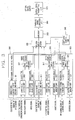
- Figure 3 is a block diagram showing a construction of a serial data conversion apparatus according to the present invention.
- the serial data conversion apparatus comprises: a video signal packet conversion unit 300 for converting a characteristic signal of a video signal into a video signal characteristic packet and simultaneously converting a video signal into a video signal packet by the characteristic signal of a video signal, horizontal/ vertical synchronization signals, and a video clock signal; an audio signal packet conversion unit 310 for converting a characteristic signal of an audio signal into an audio signal characteristic packet and simultaneously converting an audio signal into an audio signal packet by the characteristic signal of an audio signal, left/ right control signals, and an audio clock signal; a control signal packet conversion unit 320 for converting a control signal into a control signal packet by an informing signal which informs a generation of a control signal; a fourth multiplexer 330 for switching and selecting the video signal characteristic packet, the video signal packet, the audio signal characteristic packet, the audio signal packet, and the control signal packet by a certain format structure; a switching control unit 340 for controlling a conversion of the video signal packet, the audio signal packet, and the control signal packet and controlling a switching operation of the video signal
- the video signal packet conversion unit 300 includes: a video signal characteristic recognizing unit 301 for recognizing video signal characteristics by a characteristic signal of a video signal, generating a video signal characteristic packet and outputting; a video signal control unit 303 for generating a header and a tail of a video signal by video signal characteristics recognized by the video signal characteristic recognizing unit, horizontal/ vertical synchronization signals, and a video clock signal and simultaneously controlling a storage and an output of a video signal; a video signal memory unit 305 for storing and outputting a video signal by a control of the video signal control unit 303; and a first multiplexer 307 for selecting a header and a tail of the video signal control unit 303 and a video signal of the video signal memory unit 305 by a control of the switching control unit and thus generating a video signal packet.
- a video signal characteristic recognizing unit 301 for recognizing video signal characteristics by a characteristic signal of a video signal, generating a video signal characteristic packet and outputting
- a video signal control unit 303 for
- the audio signal packet conversion unit 310 includes: an audio signal characteristic recognizing unit 311 for recognizing audio signal characteristics by a characteristic signal of an audio signal, generating an audio signal characteristic packet, and outputting; an audio signal control unit 313 for generating a header and a tail of an audio signal by audio signal characteristics recognized by the audio signal characteristic recognizing unit, left/ right control signals, and an audio clock signal and simultaneously controlling a storage and an output of an audio signal; an audio signal memory unit 315 for storing and outputting an audio signal by a control of the audio signal control unit 313; and a second multiplexer 317 for selecting a header and a tail of the audio signal control unit 313 and an audio signal of the audio signal memory unit 315 by a control of the switching control unit 340 and thus generating an audio signal packet.
- an audio signal characteristic recognizing unit 311 for recognizing audio signal characteristics by a characteristic signal of an audio signal, generating an audio signal characteristic packet, and outputting
- an audio signal control unit 313 for generating a header and a tail of an audio
- control signal packet conversion unit 320 includes: a control signal control unit 321 for generating a header and a tail according to an informing signal of a control signal and controlling a storage and an output of a control signal; a control signal memory unit 323 for storing and outputting a control signal according to a control of the control signal control unit 321; and a third multiplexer 325 for selecting a header and a tail of the control signal control unit 321 and a control signal of the control signal memory unit 323 by a control of the switching control unit 340 and thus generating a control signal packet.
- the video signal characteristic recognizing unit 301 of the video signal packet conversion unit 300 recognizes video signal characteristics through a characteristic signal of a video signal inputted from outside, inputs the recognized video signal characteristics to the video signal control unit 303, and generates a video signal characteristic packet including video signal characteristics, a header, and a tail.
- the video signal control unit 303 controls a video signal to get it to be stored in the video signal memory unit 305 according to video signal characteristics inputted from the video signal characteristic recognizing unit 301, horizontal/ vertical synchronization signals inputted from outside, and a video clock signal, generates a header and a tail, and simultaneously outputs the video signal stored in the video signal memory unit 305.
- the video signal control unit 303 generates a blanking header in case that a video signal is in a blanking block, and generates an active header in case that a video signal is in an active block.
- the switching control unit 340 controls the first multiplexer 307 so that the video signal, the header, and the tail can be sequentially selected, and the first multiplexer 307 outputs a video signal packet including a video signal, a header, and a tail in parallel.
- the audio signal packet conversion unit 310 recognizes audio signal characteristics by a characteristic signal of an audio signal inputted from the audio signal characteristic recognizing unit 311, inputs the recognized audio signal characteristics to the audio signal control unit 313, and simultaneously generates an audio signal characteristic packet including audio signal characteristics, a header, and a tail.
- the audio signal control unit 303 controls an audio signal by the inputted audio signal characteristics, inputted left/ right control signals, and an audio clock signal thus to store the audio signal in the memory unit 315, generates a header and a tail, and simultaneously outputs the stored audio signal by the audio signal memory unit 315.
- the switching control unit 340 controls the second multiplexer 317 thus to select the audio signal, the header, and the tail sequentially, and the second multiplexer 317 outputs an audio signal packet including an audio signal, a header, and a tail in parallel.
- control signal packet conversion unit 320 determines a generation of a control signal by an inputted informing signal of a control signal thus to generate a header and a tail of a control signal, controls the control signal memory unit 323 thus to store a control signal, and outputs the stored control signal.
- the switching control unit 340 controls the third multiplexer 327 thus to sequentially select the control signal, the header, and the tail, and the third multiplexer 327 outputs a control signal packet including a control signal, a header, and a tail in parallel.
- a video signal characteristic packet and a video signal packet generated from the video signal packet conversion unit 300, an audio signal characteristic packet and an audio signal packet generated from the audio signal packet conversion unit 310, and a control signal packet generated from the control signal packet conversion unit 320 are respectively inputted to the fourth multiplexer 330.
- the fourth multiplexer 330 sequentially selects the video signal packet, the audio signal packet, the control signal packet, the video signal characteristic packet, and the audio signal characteristic packet and outputs by a control of the switching control unit 340. That is, the switching control unit 340 controls the fourth multiplexer 330 by the format of serial data thus to sequentially select the video signal packet, the audio signal packet, the control signal packet, the video signal characteristic packet, and the audio signal characteristic packet.
- the video signal packet, the 8-bit audio signal packet, the control signal packet, the video signal characteristic packet, and the audio signal characteristic packet sequentially selected from the fourth multiplexer 330 are inputted to the encoder 350, and converted into 10-bit data so as to be preferably transmitted as an optical signal form. Then, the data encoded by the encoder 340 is converted into serial data in the parallel/ serial conversion unit 360, and then, converted into an optical signal through the optical signal transmitting unit 370, thereby being transmitted to the display device through an optical fiber.
- the source device converts video/ audio/ control signals into serial data and then converts into an optical signal form through an optical fiber thus to transmit to the display device.
- video/audio/ control signals can be converted into serial data and transmitted through each kind of physical media.
- the source device transmits video/ audio/ and control signals to the display device through one optical cable as a packet form, so that a seeming problem can be solved.
- the display device can output clear videos and audios by restoring a clock signal, horizontal/ vertical synchronization signals, horizontal/ vertical active signals, and audio left/ right control signals by using the serial data format structure including video/ audio/ and control packet signals without directly transmitting the clock signal, the horizontal/ vertical synchronization signals, the horizontal/ vertical active signals, and the audio left/right control signals when the source device transmits video/ audio/ and the control signals to the display device as an optical signal form through an optical fiber.
Landscapes
- Engineering & Computer Science (AREA)
- Multimedia (AREA)
- Signal Processing (AREA)
- Computer Networks & Wireless Communication (AREA)
- Physics & Mathematics (AREA)
- General Physics & Mathematics (AREA)
- Theoretical Computer Science (AREA)
- Television Systems (AREA)
- Controls And Circuits For Display Device (AREA)
- Two-Way Televisions, Distribution Of Moving Picture Or The Like (AREA)
- Compression Or Coding Systems Of Tv Signals (AREA)
- Optical Communication System (AREA)
Abstract
Description
Claims (13)
- A serial data conversion apparatus comprising:a video signal packet conversion unit for converting a characteristic signal of a video signal into a video signal characteristic packet and simultaneously converting a video signal into a video signal packet by the characteristic signal of a video signal, horizontal/ vertical synchronization signals, and a video clock signal;an audio signal packet conversion unit for converting a characteristic signal of an audio signal into an audio signal characteristic packet and simultaneously converting an audio signal into an audio signal packet by the characteristic signal of an audio signal, left/ right control signals, and an audio clock signal; anda control signal packet conversion unit for converting a control signal into a control signal packet by an informing signal which informs a generation of a control signal.
- The apparatus of claim 1, wherein the video signal packet conversion unit comprises:a video signal characteristic recognizing unit for recognizing video signal characteristics by a characteristic signal of a video signal and generating a video signal characteristic packet;a video signal control unit for generating a header and a tail of a video signal by video signal characteristics recognized by the video signal characteristic recognizing unit, horizontal/ vertical synchronization signals, and a video clock signal and simultaneously controlling a storage and an output of a video signal;a video signal memory unit for storing and outputting a video signal by a control of the video signal control unit; anda multiplexer for selecting a header and a tail of the video signal control unit and a video signal of the video signal memory unit by a control of the switching control unit and thus generating a video signal packet.
- The apparatus of claim 1, wherein the audio signal packet conversion unit comprises:an audio signal characteristic recognizing unit for recognizing audio signal characteristics by a characteristic signal of an audio signal and generating an audio signal characteristic packet;an audio signal control unit for generating a header and a tail of an audio signal by audio signal characteristics recognized by the audio signal characteristic recognizing unit, left/ right control signals, and an audio clock signal and simultaneously controlling a storage and an output of an audio signal;an audio signal. memory unit for storing and outputting an audio signal by a control of the audio signal control unit; anda multiplexer for selecting a header and a tail of the audio signal control unit and an audio signal of the audio signal memory unit by a control of the switching control unit and thus generating an audio signal packet.
- The apparatus of claim 1, wherein the control signal packet conversion unit comprises:a control signal control unit for generating a header and a tail according to an informing signal of a control signal and controlling a storage and an output of a control signal;a control signal memory unit for storing and outputting a control signal according to a control of the control signal control unit; anda multiplexer for selecting a header and a tail of the control signal control unit and a control signal of the control signal memory unit by a control of the switching control unit and thus generating a control signal packet.
- A serial data conversion apparatus comprising:a video signal packet conversion unit for converting a characteristic signal of a video signal into a video signal characteristic packet and simultaneously converting a video signal into a video signal packet by the characteristic signal of a video signal, horizontal/ vertical synchronization signals, and a video clock signal;an audio signal packet conversion unit for converting a characteristic signal of an audio signal into an audio signal characteristic packet and simultaneously converting an audio signal into an audio signal packet by the characteristic signal of an audio signal, left/ right control signals, and an audio clock signal;a control signal packet conversion unit for converting a control signal into a control signal packet by an informing signal which informs a generation of a control signal;a multiplexer for switching and selecting the video signal characteristic packet, the video signal packet, the audio signal characteristic packet, the audio signal packet, and the control signal packet by a certain format structure;a switching control unit for controlling a conversion of the video signal packet, the audio signal packet, and the control signal packet and controlling a switching operation of the multiplexer;an encoder for encoding an output signal of the multiplexer;a parallel/ serial conversion unit for converting an output signal of the encoder into serial data; andan optical signal transmitting unit for converting serial data converted at the parallel/ serial conversion unit into an optical signal and then transmitting.
- The apparatus of claim 5, wherein the video signal packet conversion unit comprises:a video signal characteristic recognizing unit for recognizing video signal characteristics by a characteristic signal of a video signal and generating a video signal characteristic packet;a video signal control unit for generating a header and a tail of a video signal by video signal characteristics recognized by the video signal characteristic recognizing unit, horizontal/ vertical synchronization signals, and a video clock signal and simultaneously controlling a storage and an output of a video signal;a video signal memory unit for storing and outputting a video signal by a control of the video signal control unit; anda multiplexer for selecting a header and a tail of the video signal control unit and a video signal of the video signal memory unit by a control of the switching control unit and thus generating a video signal packet.
- The apparatus of claim 5, wherein the audio signal packet conversion unit comprises:an audio signal characteristic recognizing unit for recognizing audio signal characteristics by a characteristic signal of an audio signal and generating an audio signal characteristic packet;an audio signal control unit for generating a header and a tail of an audio signal by audio signal characteristics recognized by the audio signal characteristic recognizing unit, left/ right control signals, and an audio clock signal and simultaneously controlling a storage and an output of an audio signal;an audio signal memory unit for storing and outputting an audio signal by a control of the audio signal control unit; anda multiplexer for selecting a header and a tail of the audio signal control unit and an audio signal of the audio signal memory unit by a control of the switching control unit and thus generating an audio signal packet.
- The apparatus of claim 5, wherein the control signal packet conversion unit comprises:a control signal control unit for generating a header and a tail according to an informing signal of a control signal and controlling a storage and an output of a control signal;a control signal memory unit for storing and outputting a control, signal according to a control of the control signal control unit; anda multiplexer for selecting a header and a tail of the control signal control unit and a control signal of the control signal memory unit by a control of the switching control unit and thus generating a control signal packet.
- A serial data format structure comprising:a plurality of video signal packets including a header and a tail for informing a start and an end of a video signal of a first horizontal line;an audio signal packet including left/ right audio signals;a control signal packet including a control signal;a video signal characteristic packet including resolution information of a video signal; andan audio signal characteristic packet including left/ right control signals of an audio signal and frequency information of an audio clock signal.
- The structure of claim 9, wherein the audio signal packet, the control signal packet, the video signal characteristic packet, and the audio signal characteristic packet are formed between the plurality of video signal packets.
- The structure of claim 9, wherein the plurality of video signal packets are provided with a blanking header in case that a video signal is in a blanking block, and are provided with an active header a in case that a video signal is in an active block.
- The structure of claim 9, wherein the audio signal packet, the control signal packet, the video signal characteristic packet, and the audio signal characteristic packet include a header and a tail, respectively.
- The structure of claim 9, wherein an arrangement order of the audio signal packet, the control signal packet, the video signal characteristic packet, and the audio signal characteristic packet can be respectively changed.
Applications Claiming Priority (2)
| Application Number | Priority Date | Filing Date | Title |
|---|---|---|---|
| KR10-2002-0056203A KR100479391B1 (en) | 2002-09-16 | 2002-09-16 | Format structure of serial data and apparatus for converting the same |
| KR2002056203 | 2002-09-16 |
Publications (2)
| Publication Number | Publication Date |
|---|---|
| EP1426954A2 true EP1426954A2 (en) | 2004-06-09 |
| EP1426954A3 EP1426954A3 (en) | 2006-12-06 |
Family
ID=36087777
Family Applications (1)
| Application Number | Title | Priority Date | Filing Date |
|---|---|---|---|
| EP03020029A Ceased EP1426954A3 (en) | 2002-09-16 | 2003-09-04 | Format structure of serial data and serial data conversion apparatus |
Country Status (4)
| Country | Link |
|---|---|
| US (1) | US7376188B2 (en) |
| EP (1) | EP1426954A3 (en) |
| KR (1) | KR100479391B1 (en) |
| CN (1) | CN1225123C (en) |
Families Citing this family (4)
| Publication number | Priority date | Publication date | Assignee | Title |
|---|---|---|---|---|
| US7200767B2 (en) * | 2002-12-27 | 2007-04-03 | Texas Instruments Incorporated | Maintaining synchronization of multiple data channels with a common clock signal |
| JP3786121B2 (en) * | 2004-03-09 | 2006-06-14 | セイコーエプソン株式会社 | Data transfer control device and electronic device |
| JP3786120B2 (en) | 2004-03-09 | 2006-06-14 | セイコーエプソン株式会社 | Data transfer control device and electronic device |
| JP4929584B2 (en) * | 2004-11-04 | 2012-05-09 | ソニー株式会社 | Signal processing method, signal processing apparatus, and semiconductor device for detecting physical quantity distribution |
Family Cites Families (15)
| Publication number | Priority date | Publication date | Assignee | Title |
|---|---|---|---|---|
| JP3329076B2 (en) * | 1994-06-27 | 2002-09-30 | ソニー株式会社 | Digital signal transmission method, digital signal transmission device, digital signal reception method, and digital signal reception device |
| JP3319347B2 (en) * | 1997-07-08 | 2002-08-26 | 松下電器産業株式会社 | Recording and playback device |
| KR100327200B1 (en) * | 1998-03-07 | 2002-04-17 | 윤종용 | Method and apparatus for sending/receiving image signal |
| US6323909B1 (en) * | 1998-10-28 | 2001-11-27 | Hughes Electronics Corporation | Method and apparatus for transmitting high definition television programming using a digital satellite system transport and MPEG-2 packetized elementary streams (PES) |
| KR100319856B1 (en) * | 1998-11-04 | 2002-02-19 | 윤종용 | Video signal transmitter |
| DE69938118T2 (en) * | 1998-11-09 | 2009-02-05 | Sony Corp. | Data recording device and method |
| CA2320347A1 (en) * | 1998-12-07 | 2000-06-15 | Tomotaka Takeuchi | Serial digital interface system transmission/reception method and device therefor |
| US6690428B1 (en) * | 1999-09-13 | 2004-02-10 | Nvision, Inc. | Method and apparatus for embedding digital audio data in a serial digital video data stream |
| KR100754155B1 (en) * | 2000-08-14 | 2007-09-03 | 삼성전자주식회사 | Optical transmission device and method of graphic signal |
| KR100374605B1 (en) * | 2000-10-25 | 2003-03-04 | 삼성전자주식회사 | A apparatus and method for transmitting optical signal of graphic signal |
| US7356051B2 (en) * | 2001-01-24 | 2008-04-08 | Broadcom Corporation | Digital visual interface with audio and auxiliary data cross reference to related applications |
| JP4038996B2 (en) * | 2001-04-27 | 2008-01-30 | 松下電器産業株式会社 | Signal processing apparatus and signal processing method |
| US6751239B2 (en) * | 2001-10-05 | 2004-06-15 | Teraburst Networks, Inc. | Immersive visualization theater system and method |
| JP4491771B2 (en) * | 2001-11-29 | 2010-06-30 | 日本ビクター株式会社 | Optical transmission / reception system |
| KR100454906B1 (en) * | 2002-02-01 | 2004-11-06 | 엘지전자 주식회사 | Method for interfacing source device and display apparatus |
-
2002
- 2002-09-16 KR KR10-2002-0056203A patent/KR100479391B1/en not_active Expired - Fee Related
-
2003
- 2003-09-04 EP EP03020029A patent/EP1426954A3/en not_active Ceased
- 2003-09-12 US US10/660,619 patent/US7376188B2/en not_active Expired - Lifetime
- 2003-09-16 CN CNB031581765A patent/CN1225123C/en not_active Expired - Fee Related
Non-Patent Citations (1)
| Title |
|---|
| None |
Also Published As
| Publication number | Publication date |
|---|---|
| EP1426954A3 (en) | 2006-12-06 |
| KR20040024766A (en) | 2004-03-22 |
| KR100479391B1 (en) | 2005-03-28 |
| HK1065670A1 (en) | 2005-02-25 |
| CN1225123C (en) | 2005-10-26 |
| CN1496126A (en) | 2004-05-12 |
| US7376188B2 (en) | 2008-05-20 |
| US20040051655A1 (en) | 2004-03-18 |
Similar Documents
| Publication | Publication Date | Title |
|---|---|---|
| KR100454905B1 (en) | Method for interfacing of stream source device and display apparatus | |
| US8738809B2 (en) | Electronic device, display system, transmission method and display method | |
| US20090051820A1 (en) | Electronic device | |
| KR100454906B1 (en) | Method for interfacing source device and display apparatus | |
| KR100453967B1 (en) | Stream source device and display apparatus | |
| US7376188B2 (en) | Format structure of serial data and serial data conversion apparatus | |
| US7450117B2 (en) | Apparatus and method for restoring active signal and synchronous signal | |
| CN101620410A (en) | Electronic device | |
| KR100522733B1 (en) | Stream source device, display apparatus and method of interfacing them | |
| JP2005311776A (en) | Video playback device | |
| KR100479464B1 (en) | Apparatus for processing reset signal of source device and display device | |
| KR100491442B1 (en) | Apparatus for restoring a horizontal active signal and synchronizing signal | |
| KR100491441B1 (en) | Apparatus for restoring active signal and synchronizing signal | |
| CN1461145A (en) | Display system and method for controlling display system | |
| KR100479392B1 (en) | Apparatus for interfacing data | |
| KR100486647B1 (en) | Apparatus for processing audio mode data in source device and display device in transmitting audio signal through optical fiber | |
| KR100497417B1 (en) | Apparatus for processing audio signal in source device and in display device for transmitting audio signal through optical fiber | |
| CN100534128C (en) | AV system | |
| HK1065670B (en) | Format structure of serial data and serial data conversion apparatus | |
| KR100486646B1 (en) | Apparatus for processing video mode data in source device and in display in transmitting video signal through optical fiber | |
| KR20230072220A (en) | Integrated board control system | |
| JP2004350328A (en) | Tuner, monitor, video and audio playback device | |
| HK1065669B (en) | Apparatus and method for restoring active signal and synchronous signal | |
| KR20000034261A (en) | Mode display device of digital TV receiving system |
Legal Events
| Date | Code | Title | Description |
|---|---|---|---|
| PUAI | Public reference made under article 153(3) epc to a published international application that has entered the european phase |
Free format text: ORIGINAL CODE: 0009012 |
|
| AK | Designated contracting states |
Kind code of ref document: A2 Designated state(s): AT BE BG CH CY CZ DE DK EE ES FI FR GB GR HU IE IT LI LU MC NL PT RO SE SI SK TR |
|
| AX | Request for extension of the european patent |
Extension state: AL LT LV MK |
|
| RIN1 | Information on inventor provided before grant (corrected) |
Inventor name: PARK, JONG-SEOK Inventor name: HAN, DONG-IL Inventor name: JO, NAM-SEOK Inventor name: JOUNG, CHUL-YONG Inventor name: HWANG, HA-JIN Inventor name: SEO, SANG IL |
|
| RIN1 | Information on inventor provided before grant (corrected) |
Inventor name: PARK, JONG-SEOK Inventor name: HAN, DONG-IL Inventor name: JO, NAM-SEOK Inventor name: JOUNG, CHUL-YONG Inventor name: HWANG, HA-JIN Inventor name: SEO, SANG IL |
|
| PUAL | Search report despatched |
Free format text: ORIGINAL CODE: 0009013 |
|
| AK | Designated contracting states |
Kind code of ref document: A3 Designated state(s): AT BE BG CH CY CZ DE DK EE ES FI FR GB GR HU IE IT LI LU MC NL PT RO SE SI SK TR |
|
| AX | Request for extension of the european patent |
Extension state: AL LT LV MK |
|
| 17P | Request for examination filed |
Effective date: 20070412 |
|
| AKX | Designation fees paid |
Designated state(s): DE FR GB IT |
|
| 17Q | First examination report despatched |
Effective date: 20081229 |
|
| STAA | Information on the status of an ep patent application or granted ep patent |
Free format text: STATUS: THE APPLICATION HAS BEEN REFUSED |
|
| 18R | Application refused |
Effective date: 20131008 |