EP1426946A1 - Media-detection systems - Google Patents
Media-detection systems Download PDFInfo
- Publication number
- EP1426946A1 EP1426946A1 EP03257361A EP03257361A EP1426946A1 EP 1426946 A1 EP1426946 A1 EP 1426946A1 EP 03257361 A EP03257361 A EP 03257361A EP 03257361 A EP03257361 A EP 03257361A EP 1426946 A1 EP1426946 A1 EP 1426946A1
- Authority
- EP
- European Patent Office
- Prior art keywords
- cartridge
- data
- media
- sensor
- receiving device
- Prior art date
- Legal status (The legal status is an assumption and is not a legal conclusion. Google has not performed a legal analysis and makes no representation as to the accuracy of the status listed.)
- Granted
Links
Images



Classifications
-
- G—PHYSICS
- G11—INFORMATION STORAGE
- G11B—INFORMATION STORAGE BASED ON RELATIVE MOVEMENT BETWEEN RECORD CARRIER AND TRANSDUCER
- G11B15/00—Driving, starting or stopping record carriers of filamentary or web form; Driving both such record carriers and heads; Guiding such record carriers or containers therefor; Control thereof; Control of operating function
- G11B15/675—Guiding containers, e.g. loading, ejecting cassettes
- G11B15/68—Automatic cassette changing arrangements; automatic tape changing arrangements
-
- G—PHYSICS
- G11—INFORMATION STORAGE
- G11B—INFORMATION STORAGE BASED ON RELATIVE MOVEMENT BETWEEN RECORD CARRIER AND TRANSDUCER
- G11B17/00—Guiding record carriers not specifically of filamentary or web form, or of supports therefor
- G11B17/02—Details
- G11B17/04—Feeding or guiding single record carrier to or from transducer unit
-
- G—PHYSICS
- G11—INFORMATION STORAGE
- G11B—INFORMATION STORAGE BASED ON RELATIVE MOVEMENT BETWEEN RECORD CARRIER AND TRANSDUCER
- G11B17/00—Guiding record carriers not specifically of filamentary or web form, or of supports therefor
- G11B17/22—Guiding record carriers not specifically of filamentary or web form, or of supports therefor from random access magazine of disc records
Definitions
- the invention generally pertains to media-detection systems, and more specifically, to media-detection systems for cartridge-receiving devices.
- Media storage systems are well-known in the art and are commonly used to store data cartridges at known locations and to retrieve the desired data cartridges so that data may be written to and/or read from the data cartridges. Such media storage systems are often referred to as autochangers or library storage systems.
- a typical autochanger or media storage system may include one or more different types of cartridge-receiving devices.
- one type of cartridge-receiving device may comprise an individual cartridge storage location (e.g., for holding a single data cartridge) or a storage rack or "magazine" (e.g., for holding a plurality of data cartridges).
- Another type of cartridge-receiving device may comprise one or more cartridge read/write devices for reading data from and/or writing data to data cartridges.
- Yet another type of cartridge-receiving device is a cartridge-engaging assembly or "picker". The cartridge-engaging assembly is provided for transporting the data cartridges in the media storage system (e.g., between the storage magazines and the read/write device).
- One way to determine whether a data cartridge is present in a cartridge-receiving device is by monitoring mechanical switches.
- a switch is thrown (e.g., turned “on” or “off") to indicate the presence or absence of the data cartridge.
- mechanical switches have finite tolerances; a smaller data cartridge may pass into or out of the cartridge-receiving device undetected. This especially occurs if different sizes of data cartridges are to be used in the same media storage system.
- LTO linear tape open
- DLT digital linear tape
- Media-detection system for a cartridge-receiving device may comprise a cartridge-referencing member mounted to the cartridge-receiving device.
- the cartridge-referencing member is resiliently displaceable by a data cartridge received in the cartridge-receiving device.
- a sensor is operatively associated with the cartridge-referencing member, the sensor detecting the data cartridge in the cartridge-receiving device based on the displacement of the cartridge-referencing member.
- a method for detecting media in a cartridge-receiving device may comprise receiving the data cartridge within the cartridge-receiving device, and determining a size of the data cartridge received within the cartridge-receiving device.
- FIG. 1 is a plan view of a media storage system as it may be used according to one embodiment of the invention to store and access data cartridges therein;
- FIG. 2 is a perspective view of one embodiment of a cartridge-engaging assembly for use with the media storage system shown in FIG. 1;
- FIG. 3 is a simplified side view of the cartridge-engaging assembly shown in FIG. 2 showing a media-detection system according to one embodiment of the invention
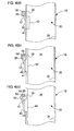
- FIG.s 4(a) through 4(c) are simplified front views of the cartridge-engaging assembly taken along line 4-4 of FIG. 3, illustrating operation of the media-detection system according to one embodiment of the invention.
- FIG. 5 is a simplified side view of the cartridge-engaging assembly shown in FIG. 2 showing a media-detection system according to another embodiment of the invention.
- media storage systems 12 are used to store large volumes of computer-readable data.
- the computer-readable data is typically stored on multiple data cartridges 14 in the media storage system 12.
- Storage magazine(s) 16 may be arranged in the media storage system 12, for example, in the generally U-shaped configuration shown in FIG. 1, although other arrangements are also possible.
- the media storage system 12 may also include a cartridge-engaging assembly 18 that can be operated to retrieve and transport data cartridges 14 between the storage magazines 16 and read/write device(s) 20.
- a host computer may issue a request to access a data cartridge 14 stored in one of the storage magazines 16 to read and/or write data thereto.
- a controller moves the cartridge-engaging assembly 18 along a positioning rail 22 (i.e., in the directions of arrow 24) until the cartridge-engaging assembly 18 is positioned adjacent the requested data cartridge 14 (e.g., at position 26).
- the controller signals the cartridge-engaging assembly 18 to withdraw the data cartridge 14 from the storage magazine 16.
- the controller then moves the cartridge-engaging assembly 18 along the positioning rail 22 until it is adjacent the read/write device 20 (e.g., at position 26'), where the data cartridge 14 is unloaded for a read and/or write operation.
- FIG. 2 An exemplary cartridge-engaging assembly 18, for use with the media storage system 12, is shown in FIG. 2 with one side removed.
- the cartridge-engaging assembly 18 may comprise a frame assembly 28 that defines a cavity or chamber 30 therein, which is sized to receive the data cartridge 14 (e.g., for carrying it to the read/write device 20).
- a cartridge-plunge mechanism 34 is slidably mounted to the frame assembly 28 so that the cartridge-plunge mechanism 34 may be extended and retracted in the directions illustrated by arrows 31, 32, respectively.
- Cartridge-plunge mechanism 34 may also be provided with a finger assembly 36 configured to engage data cartridges 14. Movement of the cartridge-engaging assembly 18 may be achieved via actuator system 38 that moves the cartridge-engaging assembly 18 along the U-shaped path defined in the media storage system 12 by the positioning rail 22.
- the cartridge-engaging assembly 18 may be provided with a cartridge-referencing member 40, shown in FIG. 2 and FIG. 3.
- Cartridge-referencing member 40 comprises a head portion 42 mounted or formed on resilient arm 44.
- the resilient arm 44 may be, for example, a plastic or stainless steel leaf spring attached on one end to sidewall 35 of the cartridge-engaging assembly 18.
- the head portion 42 extends through opening 41 formed in sidewall 35 to engage data cartridge 14 when cartridge 14 is inserted into chamber 30 of the cartridge-engaging assembly 18.
- the resilient arm 44 is flexible, enabling the head portion 42 to move outward from within chamber 30 when data cartridge 14 is inserted therein.
- Resilient arm 44 also applies a biasing force to the data cartridge 14 to hold it in a registration position in chamber 30 (i.e., against opposite sidewall 35), as illustrated in FIG. 4(b). Accordingly, the cartridge-engaging assembly 18 is adapted to receive different size data cartridges 14.
- the cartridge-referencing member 40 may be mounted to the cartridge-engaging assembly 18 in any suitable manner.
- at least one tab 46 is provided on sidewall 35, and one end of the cartridge-referencing member 40 is slid therebetween.
- the cartridge-referencing member 40 may be mounted using other suitable means such as a rivet, screw, glue, etc.
- cartridge-referencing member 40 is not limited to any particular design.
- the cartridge-referencing member 40 may be provided with a roller or bearing member mounted to the head portion 42 to engage data cartridge 14 as it is received within the chamber 30.
- the cartridge-referencing member 40 may be mounted inside of chamber 30.
- the particular design of the cartridge-referencing member 40 will depend upon various design considerations, such as, but not limited to, the desired resiliency and durability, space-saving measures, and cost of manufacture.
- the cartridge-engaging assembly 18 may be provided with media-detection system 10.
- the media-detection system 10 may be used to distinguish between narrower LTO data cartridges (approximately 21.5 millimeters (mm) wide) and wider DLT data cartridges (approximately 25.4 mm wide). Accordingly, more than one size data cartridge may be used at the same time in a "mixed" media storage system 12.
- Media-detection system 10 is shown according to one embodiment of the invention in FIG. 3 (see also FIG. 4(a)).
- Media-detection system 10 may comprise a flag 50 mounted or formed on (e.g., molded over) the cartridge-referencing member 40.
- support member 51 with the flag 50 may be mounted to the cartridge-referencing member 40.
- flag 50 extends within the detection range of sensor 52 (see FIG. 4(a)).
- a sensor 52 may be mounted to the sidewall 35 (see FIG. 3 and FIG. 4(a)) of the cartridge-engaging assembly 18. Such sensor is operatively associated with the flag 50 to determine the position of the flag 50. Accordingly, the media-detection system 10 may be used to determine the presence or absence of a data cartridge 14 in chamber 30 of the cartridge-engaging assembly 18 based on the position of the flag 50. In addition, media-detection system 10 may also be used to determine the size of data cartridge 14 received in chamber 30 based on the position of flag 50. Use of the media-detection system 10 is discussed in more detail below.
- sensor 52 may be mounted to cartridge-engaging assembly 18 in any suitable manner. Indeed, sensor 52 need not be mounted to one of the sidewalls 35 of cartridge-engaging assembly 18. For example, in another embodiment sensor 52 may be mounted to the top of cartridge-engaging assembly 18 and operatively associated with a flag indicating the height of data cartridge 14.
- any suitable sensor 52 may be used to determine the position of flag 50.
- sensor 52 may comprise a signal emitter and a signal detector. The sensor 52 would then determine the position of the flag 50 based on signals it received. It is also noted that any suitable flag 50 may be used with sensor 52 according to the teachings of the invention.
- sensor 52 may comprise at least one light emitting diode (LED) or other suitable light source and at least one photo-detector positioned opposite the light source.
- the flag 50 may be manufactured from an opaque material and assembled so that it moves between the light source and photo-detector(s), as illustrated in FIG. 4 (a) through 4(c). The flag 50 thus blocks all or a portion of the optical path between the light source and the photo-detector. Accordingly, sensor 52 is used to detect the position of flag 50.
- the senor 52 comprises a mechanical limit switch that can be "thrown” or otherwise activated or alternatively, deactivated, by movement of flag 50. Yet other embodiments are also contemplated as being within the scope of the invention.
- FIG. 4(a) through FIG. 4(c) Operation of media-detection system 10 according to one embodiment of the invention is illustrated in FIG. 4(a) through FIG. 4(c).
- FIG. 4(a) the chamber 30 of the cartridge-engaging assembly 18 is shown empty.
- the head portion 42 of cartridge-referencing member 40 extends through the opening 41 formed in the sidewall 35.
- the flag 50 covers or blocks optical emitters 55 and 56 (FIG. 4(c)) of sensor 52.
- a fully-blocked optical path corresponds to the absence of a data cartridge 14 in the cartridge-engaging assembly 30.
- FIG. 4(b) and FIG. 4(c) When data cartridge 14 is loaded into the cartridge-engaging assembly 18, data cartridge 14 contacts head portion 42 of the cartridge-referencing member 40 and moves it outward, as shown in FIG. 4(b) and FIG. 4(c).
- an LTO data cartridge 14 is shown received in chamber 30 of the cartridge-engaging assembly 18 in FIG. 4(b)
- a DLT data cartridge 14 is shown received in chamber 30 of the cartridge-engaging assembly 18 in FIG. 4(c).
- the cartridge-referencing member 40 moves to enable different size data cartridges 14 to pass into the chamber 30 and to retain data cartridge 14 in a registration position therein (i.e., adjacent one of the sidewalls 35).
- the flag 50 also moves, unblocking a portion of the optical path in sensor 52.
- the narrower LTO data cartridge 14 is received in chamber 30
- one of the light sources 55 is unblocked.
- two of the light sources 55, 56 are unblocked.
- a single light source may be used, wherein the intensity or amount (e.g., percentage) of light is detected by the sensor 52.
- a control system 15 (e.g., comprising computer-readable program code stored on computer-readable media) operatively associated with media-detection system 10 interprets the signal detected by sensor 52. For example, when the optical path is fully blocked, the control system 15 determines that chamber 30 is empty. When the optical path is at least partially unblocked, the control system 15 determines that data cartridge 14 is present in chamber 30.
- a signal from one of the sources 55 corresponds to a narrower data cartridge 14 (e.g., an LTO data cartridge).
- a signal from both sources 55, 56 corresponds to a wider data cartridge 14 (e.g., a DLT data cartridge).
- the control system 15 can determine, track and manage different or mixed media types in the same media storage system 12.
- FIG. 5 Another embodiment of a media-detection system 110 is shown in FIG. 5 according to the teachings of the invention.
- a proximity sensor 152 is mounted to sidewall 35 of the cartridge-engaging assembly 18.
- the proximity sensor 152 is positioned to transmit a signal into chamber 30 toward the opposite sidewall 35, and receive the signal when it is reflected by either data cartridge 14 in chamber 30, or the opposite sidewall 35, as the case may be.
- the proximity sensor 152 may comprise an optical or ultrasonic proximity sensor.
- Proximity sensor 152 emits a signal (e.g., an infrared signal or an ultrasonic signal) into chamber 30. The signal travels through chamber 30 until it comes into contact with data cartridge 14, if such is present, or the opposite sidewall 35, whereupon the signal is reflected back toward the sensor 152. The reflected signal is received by the proximity sensor and the strength of the reflected signal is indicative of the distance from the sensor 152 to the surface from which the signal was reflected.
- a signal e.g., an infrared signal or an ultrasonic signal
- the distance indicated by the reflected signal may be used to determine the presence (or absence) of the data cartridge 14 in chamber 30.
- chamber 30 is empty when the distance detected by sensor 152 is equal to the distance across chamber 30 to the opposite sidewall 35.
- data cartridge 14 is present in chamber 30 when the distance detected by sensor 152 is less than the distance to the opposite sidewall 35.
- the distance from the sensor 152 to the opposite sidewall 35 is thirty millimeters.
- the chamber 30 is empty.
- the distance detected by sensor 152 is less than thirty millimeters, data cartridge 14 is present in chamber 30.
- the distance detected by the sensor 152 may be used to determine the size, and hence the type of data cartridge 14 present in chamber 30.
- a 21.5 mm data cartridge e.g., an LTO data cartridge
- a 25.4 mm data cartridge e.g., a DLT data cartridge
- media-detection system 10, 110 may be used with any cartridge-receiving device, and is not limited to use with cartridge-engaging assembly 18.
- media-detection system 10, 110 may be used to detect the presence or absence, and/or the size of data cartridge 14 in storage magazine(s) 16 and/or read/write device(s) 20.
Landscapes
- Automatic Tape Cassette Changers (AREA)
- Automatic Disk Changers (AREA)
Abstract


Description
- The invention generally pertains to media-detection systems, and more specifically, to media-detection systems for cartridge-receiving devices.
- Media storage systems are well-known in the art and are commonly used to store data cartridges at known locations and to retrieve the desired data cartridges so that data may be written to and/or read from the data cartridges. Such media storage systems are often referred to as autochangers or library storage systems.
- A typical autochanger or media storage system may include one or more different types of cartridge-receiving devices. For example, one type of cartridge-receiving device may comprise an individual cartridge storage location (e.g., for holding a single data cartridge) or a storage rack or "magazine" (e.g., for holding a plurality of data cartridges). Another type of cartridge-receiving device may comprise one or more cartridge read/write devices for reading data from and/or writing data to data cartridges. Yet another type of cartridge-receiving device is a cartridge-engaging assembly or "picker". The cartridge-engaging assembly is provided for transporting the data cartridges in the media storage system (e.g., between the storage magazines and the read/write device).
- In operation, it is often useful to know whether a data cartridge is present in any of the various cartridge-receiving devices. At start-up, for example, it may be necessary to know whether there is already a data cartridge in the cartridge-engaging assembly which should be returned to a storage magazine before the media storage system will be ready for service.
- One way to determine whether a data cartridge is present in a cartridge-receiving device is by monitoring mechanical switches. When a data cartridge passes into or out of the cartridge-receiving device, a switch is thrown (e.g., turned "on" or "off") to indicate the presence or absence of the data cartridge. However, mechanical switches have finite tolerances; a smaller data cartridge may pass into or out of the cartridge-receiving device undetected. This especially occurs if different sizes of data cartridges are to be used in the same media storage system.
- It may also be useful to know which size data cartridge is present in the cartridge-receiving device. For example, if a smaller linear tape open (LTO) data cartridge is being retrieved for a read/write operation, it may be necessary to deliver the data cartridge to a read/write device designed for smaller LTO data cartridges. Alternatively, if a larger digital linear tape (DLT) data cartridge is being retrieved for a read/write operation, it may be necessary to deliver the data cartridge to a different read/write device designed for larger DLT data cartridges. Current approaches rely on separation of the different types and sizes of media into physically different media storage systems.
- Media-detection system for a cartridge-receiving device may comprise a cartridge-referencing member mounted to the cartridge-receiving device. The cartridge-referencing member is resiliently displaceable by a data cartridge received in the cartridge-receiving device. A sensor is operatively associated with the cartridge-referencing member, the sensor detecting the data cartridge in the cartridge-receiving device based on the displacement of the cartridge-referencing member.
- A method for detecting media in a cartridge-receiving device may comprise receiving the data cartridge within the cartridge-receiving device, and determining a size of the data cartridge received within the cartridge-receiving device.
- Illustrative and presently preferred embodiments of the invention are shown in the drawings, in which:
- FIG. 1 is a plan view of a media storage system as it may be used according to one embodiment of the invention to store and access data cartridges therein;
- FIG. 2 is a perspective view of one embodiment of a cartridge-engaging assembly for use with the media storage system shown in FIG. 1;
- FIG. 3 is a simplified side view of the cartridge-engaging assembly shown in FIG. 2 showing a media-detection system according to one embodiment of the invention;
- FIG.s 4(a) through 4(c) are simplified front views of the cartridge-engaging assembly taken along line 4-4 of FIG. 3, illustrating operation of the media-detection system according to one embodiment of the invention; and
- FIG. 5 is a simplified side view of the cartridge-engaging assembly shown in FIG. 2 showing a media-detection system according to another embodiment of the invention.
- An embodiment of a media-detection system 10 (FIG. 4) is shown and described herein as it may be used in media storage system 12 (FIG. 1). Briefly,
media storage systems 12 are used to store large volumes of computer-readable data. The computer-readable data is typically stored onmultiple data cartridges 14 in themedia storage system 12. Storage magazine(s) 16 may be arranged in themedia storage system 12, for example, in the generally U-shaped configuration shown in FIG. 1, although other arrangements are also possible. Themedia storage system 12 may also include a cartridge-engaging assembly 18 that can be operated to retrieve and transportdata cartridges 14 between thestorage magazines 16 and read/write device(s) 20. - As an illustration of the use of the
media storage system 12, a host computer (not shown) may issue a request to access adata cartridge 14 stored in one of thestorage magazines 16 to read and/or write data thereto. In response, a controller moves the cartridge-engagingassembly 18 along a positioning rail 22 (i.e., in the directions of arrow 24) until the cartridge-engaging assembly 18 is positioned adjacent the requested data cartridge 14 (e.g., at position 26). Once positioned, the controller signals the cartridge-engagingassembly 18 to withdraw thedata cartridge 14 from thestorage magazine 16. The controller then moves the cartridge-engagingassembly 18 along thepositioning rail 22 until it is adjacent the read/write device 20 (e.g., at position 26'), where thedata cartridge 14 is unloaded for a read and/or write operation. - An exemplary cartridge-
engaging assembly 18, for use with themedia storage system 12, is shown in FIG. 2 with one side removed. The cartridge-engaging assembly 18 may comprise aframe assembly 28 that defines a cavity orchamber 30 therein, which is sized to receive the data cartridge 14 (e.g., for carrying it to the read/write device 20). - A cartridge-
plunge mechanism 34 is slidably mounted to theframe assembly 28 so that the cartridge-plunge mechanism 34 may be extended and retracted in the directions illustrated byarrows plunge mechanism 34 may also be provided with afinger assembly 36 configured to engagedata cartridges 14. Movement of the cartridge-engaging assembly 18 may be achieved viaactuator system 38 that moves the cartridge-engagingassembly 18 along the U-shaped path defined in themedia storage system 12 by thepositioning rail 22. - Also according to one embodiment of the invention, the cartridge-
engaging assembly 18 may be provided with a cartridge-referencing member 40, shown in FIG. 2 and FIG. 3. Cartridge-referencing member 40 comprises ahead portion 42 mounted or formed onresilient arm 44. Theresilient arm 44 may be, for example, a plastic or stainless steel leaf spring attached on one end tosidewall 35 of the cartridge-engaging assembly 18. - The
head portion 42 extends throughopening 41 formed insidewall 35 to engagedata cartridge 14 whencartridge 14 is inserted intochamber 30 of the cartridge-engaging assembly 18. Theresilient arm 44 is flexible, enabling thehead portion 42 to move outward from withinchamber 30 whendata cartridge 14 is inserted therein.Resilient arm 44 also applies a biasing force to thedata cartridge 14 to hold it in a registration position in chamber 30 (i.e., against opposite sidewall 35), as illustrated in FIG. 4(b). Accordingly, the cartridge-engaging assembly 18 is adapted to receive differentsize data cartridges 14. - The cartridge-
referencing member 40 may be mounted to the cartridge-engagingassembly 18 in any suitable manner. In one embodiment, at least onetab 46 is provided onsidewall 35, and one end of the cartridge-referencing member 40 is slid therebetween. In other embodiments, the cartridge-referencing member 40 may be mounted using other suitable means such as a rivet, screw, glue, etc. - Of course the cartridge-
referencing member 40 is not limited to any particular design. For example, the cartridge-referencing member 40 may be provided with a roller or bearing member mounted to thehead portion 42 to engagedata cartridge 14 as it is received within thechamber 30. As another example, the cartridge-referencing member 40 may be mounted inside ofchamber 30. The particular design of the cartridge-referencingmember 40 will depend upon various design considerations, such as, but not limited to, the desired resiliency and durability, space-saving measures, and cost of manufacture. - The foregoing description of the
media storage system 12 and cartridge-engaging assembly 18 is provided in order to better understand one environment in which the invention may be used. However, it should be understood that the invention may be used in any of a wide range of other types of media storage systems, and in conjunction with any of a wide range of cartridge-engaging assemblies now known or that may be developed in the future. - In order to determine whether a
data cartridge 14 is present in, or absent from the cartridge-engaging assembly 18, and/or to determine the size ofdata cartridge 14, the cartridge-engaging assembly 18 may be provided with media-detection system 10. For example, the media-detection system 10 may be used to distinguish between narrower LTO data cartridges (approximately 21.5 millimeters (mm) wide) and wider DLT data cartridges (approximately 25.4 mm wide). Accordingly, more than one size data cartridge may be used at the same time in a "mixed"media storage system 12. - Media-
detection system 10 is shown according to one embodiment of the invention in FIG. 3 (see also FIG. 4(a)). Media-detection system 10 may comprise aflag 50 mounted or formed on (e.g., molded over) the cartridge-referencingmember 40. For example,support member 51 with theflag 50 may be mounted to the cartridge-referencingmember 40. As such,flag 50 extends within the detection range of sensor 52 (see FIG. 4(a)). Whendata cartridge 14 is received in, or removed fromchamber 30 of the cartridge-engagingassembly 18, it causes the cartridge-referencingmember 40, and hence theflag 50, to move. - A
sensor 52 may be mounted to the sidewall 35 (see FIG. 3 and FIG. 4(a)) of the cartridge-engagingassembly 18. Such sensor is operatively associated with theflag 50 to determine the position of theflag 50. Accordingly, the media-detection system 10 may be used to determine the presence or absence of adata cartridge 14 inchamber 30 of the cartridge-engagingassembly 18 based on the position of theflag 50. In addition, media-detection system 10 may also be used to determine the size ofdata cartridge 14 received inchamber 30 based on the position offlag 50. Use of the media-detection system 10 is discussed in more detail below. - It is noted that the
sensor 52 may be mounted to cartridge-engagingassembly 18 in any suitable manner. Indeed,sensor 52 need not be mounted to one of thesidewalls 35 of cartridge-engagingassembly 18. For example, in anotherembodiment sensor 52 may be mounted to the top of cartridge-engagingassembly 18 and operatively associated with a flag indicating the height ofdata cartridge 14. - In addition, any
suitable sensor 52 may be used to determine the position offlag 50. Generally,sensor 52 may comprise a signal emitter and a signal detector. Thesensor 52 would then determine the position of theflag 50 based on signals it received. It is also noted that anysuitable flag 50 may be used withsensor 52 according to the teachings of the invention. - In one embodiment,
sensor 52 may comprise at least one light emitting diode (LED) or other suitable light source and at least one photo-detector positioned opposite the light source. Theflag 50 may be manufactured from an opaque material and assembled so that it moves between the light source and photo-detector(s), as illustrated in FIG. 4 (a) through 4(c). Theflag 50 thus blocks all or a portion of the optical path between the light source and the photo-detector. Accordingly,sensor 52 is used to detect the position offlag 50. - In another embodiment, the
sensor 52 comprises a mechanical limit switch that can be "thrown" or otherwise activated or alternatively, deactivated, by movement offlag 50. Yet other embodiments are also contemplated as being within the scope of the invention. - Operation of media-
detection system 10 according to one embodiment of the invention is illustrated in FIG. 4(a) through FIG. 4(c). In FIG 4(a), thechamber 30 of the cartridge-engagingassembly 18 is shown empty. Thehead portion 42 of cartridge-referencingmember 40 extends through theopening 41 formed in thesidewall 35. In this position, theflag 50 covers or blocksoptical emitters 55 and 56 (FIG. 4(c)) ofsensor 52. Thus, a fully-blocked optical path corresponds to the absence of adata cartridge 14 in the cartridge-engagingassembly 30. - When
data cartridge 14 is loaded into the cartridge-engagingassembly 18,data cartridge 14contacts head portion 42 of the cartridge-referencingmember 40 and moves it outward, as shown in FIG. 4(b) and FIG. 4(c). For purposes of illustration, anLTO data cartridge 14 is shown received inchamber 30 of the cartridge-engagingassembly 18 in FIG. 4(b), and aDLT data cartridge 14 is shown received inchamber 30 of the cartridge-engagingassembly 18 in FIG. 4(c). The cartridge-referencingmember 40 moves to enable differentsize data cartridges 14 to pass into thechamber 30 and to retaindata cartridge 14 in a registration position therein (i.e., adjacent one of the sidewalls 35). - When the cartridge-referencing
member 40 moves outward to enable thedata cartridge 14 to be received therein, theflag 50 also moves, unblocking a portion of the optical path insensor 52. For example, in FIG. 4(b) where the narrowerLTO data cartridge 14 is received inchamber 30, one of thelight sources 55 is unblocked. In FIG. 4(c) where the widerDLT data cartridge 14 is received inchamber 30, two of thelight sources sensor 52. - A control system 15 (e.g., comprising computer-readable program code stored on computer-readable media) operatively associated with media-
detection system 10 interprets the signal detected bysensor 52. For example, when the optical path is fully blocked, thecontrol system 15 determines thatchamber 30 is empty. When the optical path is at least partially unblocked, thecontrol system 15 determines thatdata cartridge 14 is present inchamber 30. - More specifically in the illustration of FIG. 4(a) through 4(c), a signal from one of the
sources 55 corresponds to a narrower data cartridge 14 (e.g., an LTO data cartridge). A signal from bothsources control system 15 can determine, track and manage different or mixed media types in the samemedia storage system 12. - Although the above illustration is discussed in regard to an
optical sensor 52, it is understood that other suitable sensors may also be used according to the teachings of the invention. It is also understood that the invention is not limited to three states (i.e., empty - LTO - DLT), as illustrated in FIG. 4(a) through FIG. 4(c). Suitable modifications to thesensor 52 and thecontrol system 15 can readily be made by one skilled in the art after having become familiar with the teachings of the invention. - Another embodiment of a media-
detection system 110 is shown in FIG. 5 according to the teachings of the invention. According to this embodiment, a proximity sensor 152 is mounted to sidewall 35 of the cartridge-engagingassembly 18. The proximity sensor 152 is positioned to transmit a signal intochamber 30 toward theopposite sidewall 35, and receive the signal when it is reflected by eitherdata cartridge 14 inchamber 30, or theopposite sidewall 35, as the case may be. - The proximity sensor 152 may comprise an optical or ultrasonic proximity sensor. Proximity sensor 152 emits a signal (e.g., an infrared signal or an ultrasonic signal) into
chamber 30. The signal travels throughchamber 30 until it comes into contact withdata cartridge 14, if such is present, or theopposite sidewall 35, whereupon the signal is reflected back toward the sensor 152. The reflected signal is received by the proximity sensor and the strength of the reflected signal is indicative of the distance from the sensor 152 to the surface from which the signal was reflected. - The distance indicated by the reflected signal may be used to determine the presence (or absence) of the
data cartridge 14 inchamber 30. For example,chamber 30 is empty when the distance detected by sensor 152 is equal to the distance acrosschamber 30 to theopposite sidewall 35. On the other hand,data cartridge 14 is present inchamber 30 when the distance detected by sensor 152 is less than the distance to theopposite sidewall 35. - As an illustration, assume that the distance from the sensor 152 to the
opposite sidewall 35 is thirty millimeters. When the distance detected by sensor 152 is thirty millimeters, thechamber 30 is empty. When the distance detected by sensor 152 is less than thirty millimeters,data cartridge 14 is present inchamber 30. - In addition, the distance detected by the sensor 152 may be used to determine the size, and hence the type of
data cartridge 14 present inchamber 30. As an illustration, when the distance detected by the sensor 152 is 8.5 mm, a 21.5 mm data cartridge (e.g., an LTO data cartridge) is present in chamber 30 (i.e., 30 mm - 8.5 mm = 21.5 mm). When the distance detected by the sensor 152 is 4.6 mm, a 25.4 mm data cartridge (e.g., a DLT data cartridge) is present in chamber 30 (i.e., 30 mm - 4.6 mm = 25.4 mm). - It should be noted that while the invention is shown and described herein as it could be used to store and retrieve LTO and
DLT data cartridges 14 having standard sizes and configurations, it is not limited to any particular type or style of data cartridge. Consequently, the present invention should not be regarded as limited to use with LTO and DLT data cartridges. - Furthermore, media-
detection system assembly 18. For example, media-detection system data cartridge 14 in storage magazine(s) 16 and/or read/write device(s) 20.
Claims (10)
- A media-detection system (10) for a cartridge-receiving device (18), comprising:a cartridge-referencing member (40) mounted to the cartridge-receiving device, said cartridge-referencing member resiliently displaceable by a data cartridge (14) received in the cartridge-receiving device; anda sensor (52) operatively associated with said cartridge-referencing member, said sensor detecting the data cartridge in the cartridge-receiving device based on the displacement of said cartridge-referencing member.
- The media-detection system (10) of claim 1, wherein said sensor (52) detects a size of the data cartridge (14) based on the displacement of said cartridge-referencing member (40).
- The media-detection system (10) of claim 1, further comprising a flag (50) mounted to said cartridge-referencing member (40), said flag indicating to said sensor (52) the displacement of said cartridge-referencing member.
- The media-detection system (10) of claim 1, further comprising a control system (15) operatively associated with said sensor (52), said control system determining a size of the data cartridge (14) based on the displacement of said cartridge-referencing member (40).
- The media-detection system (10) of claim 1, wherein said sensor (52) is an optical switch.
- A method for detecting mixed media in a cartridge-receiving device (18), comprising:receiving the data cartridge (14) within the cartridge-receiving device; andautomatically determining a size of the data cartridge received within the cartridge-receiving device.
- The method of claim 6, further comprising:emitting a signal within the cartridge-receiving device (18), the signal reflected by the data cartridge (14); andreceiving the reflected signal for determining the size of the data cartridge.
- The method of claim 7, further comprising determining the strength of the reflected signal for determining the size of the data cartridge (14).
- The method of claim 6, further comprising determining a type of the data cartridge (14) from the size of the data cartridge.
- The method of claim 6, further comprising displacing a cartridge-referencing member (40) when the data cartridge (14) is received within the cartridge-receiving device (18), the displacement of the cartridge-referencing member indicating the size of the data cartridge.
Applications Claiming Priority (2)
| Application Number | Priority Date | Filing Date | Title |
|---|---|---|---|
| US10/308,524 US7340749B2 (en) | 2002-12-03 | 2002-12-03 | Method and apparatus to detect presence of or a size of a data cartridge |
| US308524 | 2002-12-03 |
Publications (2)
| Publication Number | Publication Date |
|---|---|
| EP1426946A1 true EP1426946A1 (en) | 2004-06-09 |
| EP1426946B1 EP1426946B1 (en) | 2006-07-26 |
Family
ID=32312226
Family Applications (1)
| Application Number | Title | Priority Date | Filing Date |
|---|---|---|---|
| EP03257361A Expired - Lifetime EP1426946B1 (en) | 2002-12-03 | 2003-11-21 | Media-detection systems |
Country Status (4)
| Country | Link |
|---|---|
| US (1) | US7340749B2 (en) |
| EP (1) | EP1426946B1 (en) |
| JP (1) | JP2004185802A (en) |
| DE (1) | DE60307027T2 (en) |
Cited By (2)
| Publication number | Priority date | Publication date | Assignee | Title |
|---|---|---|---|---|
| EP1463048A3 (en) * | 2003-03-27 | 2005-03-23 | Hewlett-Packard Development Company, L.P. | Media-detection system and method for identifying types of data catridges |
| EP1533806A3 (en) * | 2003-11-18 | 2007-02-28 | Hewlett-Packard Development Company, L.P. | Method and apparatus for detecting media |
Families Citing this family (4)
| Publication number | Priority date | Publication date | Assignee | Title |
|---|---|---|---|---|
| DE102004041283B3 (en) * | 2004-08-25 | 2006-02-02 | BDT Büro- und Datentechnik GmbH & Co. KG | Device for storing data on cassettes recorded in cartridges |
| JP2006082397A (en) * | 2004-09-16 | 2006-03-30 | Fuji Photo Film Co Ltd | Printer, image output device, and method for guiding insertion port of recording medium |
| JP5924803B2 (en) * | 2011-09-28 | 2016-05-25 | Necプラットフォームズ株式会社 | Storage device |
| JP5924804B2 (en) * | 2011-09-28 | 2016-05-25 | Necプラットフォームズ株式会社 | Storage device and storage device latch state detection method |
Citations (8)
| Publication number | Priority date | Publication date | Assignee | Title |
|---|---|---|---|---|
| US4846619A (en) * | 1985-04-08 | 1989-07-11 | Odetics, Inc. | Robotic materials handling system |
| US5099465A (en) * | 1987-05-07 | 1992-03-24 | Deutsche Thomson-Brandt Gmbh | Compact-disc changer with magazine and playback section that are movable relative to each other |
| EP0542482A2 (en) * | 1991-11-05 | 1993-05-19 | Sony Corporation | Automatic cassette changer |
| EP0833327A1 (en) * | 1996-09-25 | 1998-04-01 | Alps Electric Co., Ltd. | Disc package |
| EP1074986A1 (en) * | 1999-08-06 | 2001-02-07 | Pioneer Corporation | Cartridge receiving apparatus and cartridge disc player utilizing the same |
| EP1217621A1 (en) * | 2000-12-20 | 2002-06-26 | THOMSON multimedia S.A. | Disk changer |
| US6441984B1 (en) * | 1992-11-10 | 2002-08-27 | Sony Corporation | Cassette auto-changer with cassette accommodating portion providing cassette recording format information |
| US20020136100A1 (en) * | 2001-03-21 | 2002-09-26 | Reasoner Kelly J. | Data cartridge detector |
Family Cites Families (27)
| Publication number | Priority date | Publication date | Assignee | Title |
|---|---|---|---|---|
| DE3636784A1 (en) * | 1986-10-29 | 1988-05-05 | Thomson Brandt Gmbh | CD DISC CHANGER |
| US5009465A (en) * | 1987-08-14 | 1991-04-23 | Induni Michael L | Roll-up roof covering for automobiles with removable roof panels |
| NL8802763A (en) * | 1988-11-10 | 1990-06-01 | Philips Nv | SYSTEM FOR RECORDING AND / OR READING SIGNALS ON DATA CARRIERS IN CASSETTES. |
| JP2807119B2 (en) * | 1992-03-18 | 1998-10-08 | シャープ株式会社 | Cassette detection device for magnetic tape unit |
| US6298017B1 (en) | 1995-03-31 | 2001-10-02 | International Business Machines Corp. | Locking method and apparatus for multi-disk cartridge |
| US5612831A (en) * | 1995-09-20 | 1997-03-18 | International Business Machines Corporation | Removeable media drive unit with loader interlock to indicate presence of object |
| JP3708204B2 (en) * | 1996-03-12 | 2005-10-19 | クラリオン株式会社 | In-vehicle information device |
| JPH1064180A (en) * | 1996-08-21 | 1998-03-06 | Sony Corp | Disk drive device |
| JPH10134499A (en) * | 1996-10-25 | 1998-05-22 | Sony Corp | Disc recording and reproducing apparatus and method |
| WO1998031012A1 (en) * | 1997-01-10 | 1998-07-16 | Sony Corporation | Optical disk device and method for discriminating optical disk |
| TW469424B (en) * | 1997-04-17 | 2001-12-21 | Alps Electric Co Ltd | Disk discriminating method |
| JPH11110868A (en) * | 1997-09-30 | 1999-04-23 | Sony Corp | Disk drive |
| US6538971B2 (en) * | 1997-12-23 | 2003-03-25 | Samsung Electronics Co., Ltd. | Optical information recording/reproducing apparatus and method for using both disc cartridges holding 8cm and 12cm disc |
| US6104693A (en) * | 1998-03-20 | 2000-08-15 | Hewlett-Packard Company | Mounting system for cartridge plunge mechanism |
| US6160786A (en) * | 1998-03-20 | 2000-12-12 | Hewlett-Packard Company | Cartridge engaging assembly with rack drive thumb actuator system |
| US6031676A (en) | 1998-04-09 | 2000-02-29 | Storage Technology Corporation | System for sensing a tape cartridge |
| US6297924B1 (en) | 1998-11-13 | 2001-10-02 | Iomega Corporation | System and method for cartridge detection and verification using signal comparison |
| JP2000215586A (en) * | 1998-12-23 | 2000-08-04 | Samsung Electronics Co Ltd | Optical recording / reproducing apparatus capable of using recording media of various sizes and types and information recording / reproducing method therefor |
| US6219313B1 (en) | 1999-01-19 | 2001-04-17 | Storage Technology Corporation | System and method for adaptive cartridge engagement in an automated cartridge library |
| US6157513A (en) * | 1999-01-26 | 2000-12-05 | Hewlett-Packard Company | Thumb referencing and drive system |
| US6266316B1 (en) * | 1999-03-01 | 2001-07-24 | Hewlett-Packard Company | Automatic splaying picker finger |
| US6259579B1 (en) * | 1999-05-17 | 2001-07-10 | Hewlett-Packard Company | Picker indexing and multimedia cartridge referencing spring |
| US6213705B1 (en) | 1999-08-24 | 2001-04-10 | Storage Technology Corporation | Tape storage library apparatus having integrated camera, proximity sensor, and reach safe sensor |
| JP2001222851A (en) * | 2000-02-04 | 2001-08-17 | Sony Corp | Disk cartridge device |
| US6473706B1 (en) * | 2000-07-06 | 2002-10-29 | International Business Machines Corporation | Self-configuring and self-calibrating automated system |
| JP2002042406A (en) * | 2000-07-21 | 2002-02-08 | Alpine Electronics Inc | On-vehicle recording medium reproducer |
| US6661748B1 (en) * | 2001-03-05 | 2003-12-09 | Hewlett-Packard Development Company, L.P. | Position control for plunge mechanism |
-
2002
- 2002-12-03 US US10/308,524 patent/US7340749B2/en not_active Expired - Lifetime
-
2003
- 2003-11-21 DE DE60307027T patent/DE60307027T2/en not_active Expired - Lifetime
- 2003-11-21 EP EP03257361A patent/EP1426946B1/en not_active Expired - Lifetime
- 2003-12-01 JP JP2003401851A patent/JP2004185802A/en not_active Withdrawn
Patent Citations (8)
| Publication number | Priority date | Publication date | Assignee | Title |
|---|---|---|---|---|
| US4846619A (en) * | 1985-04-08 | 1989-07-11 | Odetics, Inc. | Robotic materials handling system |
| US5099465A (en) * | 1987-05-07 | 1992-03-24 | Deutsche Thomson-Brandt Gmbh | Compact-disc changer with magazine and playback section that are movable relative to each other |
| EP0542482A2 (en) * | 1991-11-05 | 1993-05-19 | Sony Corporation | Automatic cassette changer |
| US6441984B1 (en) * | 1992-11-10 | 2002-08-27 | Sony Corporation | Cassette auto-changer with cassette accommodating portion providing cassette recording format information |
| EP0833327A1 (en) * | 1996-09-25 | 1998-04-01 | Alps Electric Co., Ltd. | Disc package |
| EP1074986A1 (en) * | 1999-08-06 | 2001-02-07 | Pioneer Corporation | Cartridge receiving apparatus and cartridge disc player utilizing the same |
| EP1217621A1 (en) * | 2000-12-20 | 2002-06-26 | THOMSON multimedia S.A. | Disk changer |
| US20020136100A1 (en) * | 2001-03-21 | 2002-09-26 | Reasoner Kelly J. | Data cartridge detector |
Cited By (3)
| Publication number | Priority date | Publication date | Assignee | Title |
|---|---|---|---|---|
| EP1463048A3 (en) * | 2003-03-27 | 2005-03-23 | Hewlett-Packard Development Company, L.P. | Media-detection system and method for identifying types of data catridges |
| US7006319B2 (en) | 2003-03-27 | 2006-02-28 | Hewlett-Packard Development Company, L.P. | Media-detection system and method for identifying types of data cartridges |
| EP1533806A3 (en) * | 2003-11-18 | 2007-02-28 | Hewlett-Packard Development Company, L.P. | Method and apparatus for detecting media |
Also Published As
| Publication number | Publication date |
|---|---|
| JP2004185802A (en) | 2004-07-02 |
| EP1426946B1 (en) | 2006-07-26 |
| DE60307027D1 (en) | 2006-09-07 |
| DE60307027T2 (en) | 2007-08-23 |
| US20040105352A1 (en) | 2004-06-03 |
| US7340749B2 (en) | 2008-03-04 |
Similar Documents
| Publication | Publication Date | Title |
|---|---|---|
| US8254217B2 (en) | System and method for judging presence/absence of loading spaces | |
| EP1426946B1 (en) | Media-detection systems | |
| JP2007213811A (en) | Medium-detection system and method for identifying type of data cartridge | |
| US6693858B2 (en) | Data cartridge detector | |
| EP1207490B1 (en) | Dual bar code reading system for a data storage system | |
| US7088539B2 (en) | Apparatus for detecting media | |
| US8046099B2 (en) | Library unit and magazine position detecting method in the library unit | |
| US6980884B2 (en) | Intrusion monitors for media storage systems | |
| US7477479B2 (en) | Tape drive bezel for use with multiple accessors | |
| JP2002203348A (en) | Data storage system, and method for detecting information | |
| US6925034B2 (en) | Apparatus for regulating the position of a plunge mechanism of a cartridge engaging assembly | |
| US7405901B2 (en) | Tape drive sensor system | |
| US20050036408A1 (en) | Automated storage library cartridge gripper with cartridge detector | |
| US6967791B2 (en) | Illumination systems and methods | |
| US8281328B2 (en) | Disc mounting mechanism with front and rear loading and unloading slots | |
| JPH09212977A (en) | Optical disk autochanger |
Legal Events
| Date | Code | Title | Description |
|---|---|---|---|
| PUAI | Public reference made under article 153(3) epc to a published international application that has entered the european phase |
Free format text: ORIGINAL CODE: 0009012 |
|
| AK | Designated contracting states |
Kind code of ref document: A1 Designated state(s): AT BE BG CH CY CZ DE DK EE ES FI FR GB GR HU IE IT LI LU MC NL PT RO SE SI SK TR |
|
| AX | Request for extension of the european patent |
Extension state: AL LT LV MK |
|
| 17P | Request for examination filed |
Effective date: 20041119 |
|
| AKX | Designation fees paid |
Designated state(s): DE FR GB |
|
| GRAP | Despatch of communication of intention to grant a patent |
Free format text: ORIGINAL CODE: EPIDOSNIGR1 |
|
| GRAS | Grant fee paid |
Free format text: ORIGINAL CODE: EPIDOSNIGR3 |
|
| GRAA | (expected) grant |
Free format text: ORIGINAL CODE: 0009210 |
|
| AK | Designated contracting states |
Kind code of ref document: B1 Designated state(s): DE FR GB |
|
| REG | Reference to a national code |
Ref country code: GB Ref legal event code: FG4D |
|
| REF | Corresponds to: |
Ref document number: 60307027 Country of ref document: DE Date of ref document: 20060907 Kind code of ref document: P |
|
| ET | Fr: translation filed | ||
| PLBE | No opposition filed within time limit |
Free format text: ORIGINAL CODE: 0009261 |
|
| STAA | Information on the status of an ep patent application or granted ep patent |
Free format text: STATUS: NO OPPOSITION FILED WITHIN TIME LIMIT |
|
| 26N | No opposition filed |
Effective date: 20070427 |
|
| PGFP | Annual fee paid to national office [announced via postgrant information from national office to epo] |
Ref country code: FR Payment date: 20091201 Year of fee payment: 7 Ref country code: GB Payment date: 20091125 Year of fee payment: 7 |
|
| GBPC | Gb: european patent ceased through non-payment of renewal fee |
Effective date: 20101121 |
|
| REG | Reference to a national code |
Ref country code: FR Ref legal event code: ST Effective date: 20110801 |
|
| PG25 | Lapsed in a contracting state [announced via postgrant information from national office to epo] |
Ref country code: FR Free format text: LAPSE BECAUSE OF NON-PAYMENT OF DUE FEES Effective date: 20101130 |
|
| PG25 | Lapsed in a contracting state [announced via postgrant information from national office to epo] |
Ref country code: GB Free format text: LAPSE BECAUSE OF NON-PAYMENT OF DUE FEES Effective date: 20101121 |
|
| REG | Reference to a national code |
Ref country code: DE Ref legal event code: R082 Ref document number: 60307027 Country of ref document: DE Representative=s name: SCHOPPE, ZIMMERMANN, STOECKELER, ZINKLER, SCHE, DE Ref country code: DE Ref legal event code: R081 Ref document number: 60307027 Country of ref document: DE Owner name: HEWLETT PACKARD ENTERPRISE DEVELOPMENT LP, HOU, US Free format text: FORMER OWNER: HEWLETT-PACKARD DEVELOPMENT COMPANY, L.P., HOUSTON, TEX., US |
|
| PGFP | Annual fee paid to national office [announced via postgrant information from national office to epo] |
Ref country code: DE Payment date: 20221124 Year of fee payment: 20 |
|
| REG | Reference to a national code |
Ref country code: DE Ref legal event code: R071 Ref document number: 60307027 Country of ref document: DE |