EP1426499A1 - Method and apparatus for end stroke dampening in hydraulic actuators of mobile working machines - Google Patents
Method and apparatus for end stroke dampening in hydraulic actuators of mobile working machines Download PDFInfo
- Publication number
- EP1426499A1 EP1426499A1 EP03021744A EP03021744A EP1426499A1 EP 1426499 A1 EP1426499 A1 EP 1426499A1 EP 03021744 A EP03021744 A EP 03021744A EP 03021744 A EP03021744 A EP 03021744A EP 1426499 A1 EP1426499 A1 EP 1426499A1
- Authority
- EP
- European Patent Office
- Prior art keywords
- speed
- hydraulic cylinder
- detection device
- hydraulic
- time
- Prior art date
- Legal status (The legal status is an assumption and is not a legal conclusion. Google has not performed a legal analysis and makes no representation as to the accuracy of the status listed.)
- Granted
Links
Images


Classifications
-
- F—MECHANICAL ENGINEERING; LIGHTING; HEATING; WEAPONS; BLASTING
- F15—FLUID-PRESSURE ACTUATORS; HYDRAULICS OR PNEUMATICS IN GENERAL
- F15B—SYSTEMS ACTING BY MEANS OF FLUIDS IN GENERAL; FLUID-PRESSURE ACTUATORS, e.g. SERVOMOTORS; DETAILS OF FLUID-PRESSURE SYSTEMS, NOT OTHERWISE PROVIDED FOR
- F15B21/00—Common features of fluid actuator systems; Fluid-pressure actuator systems or details thereof, not covered by any other group of this subclass
- F15B21/02—Servomotor systems with programme control derived from a store or timing device; Control devices therefor
-
- E—FIXED CONSTRUCTIONS
- E02—HYDRAULIC ENGINEERING; FOUNDATIONS; SOIL SHIFTING
- E02F—DREDGING; SOIL-SHIFTING
- E02F9/00—Component parts of dredgers or soil-shifting machines, not restricted to one of the kinds covered by groups E02F3/00 - E02F7/00
- E02F9/20—Drives; Control devices
- E02F9/22—Hydraulic or pneumatic drives
- E02F9/2203—Arrangements for controlling the attitude of actuators, e.g. speed, floating function
- E02F9/2214—Arrangements for controlling the attitude of actuators, e.g. speed, floating function for reducing the shock generated at the stroke end
-
- F—MECHANICAL ENGINEERING; LIGHTING; HEATING; WEAPONS; BLASTING
- F15—FLUID-PRESSURE ACTUATORS; HYDRAULICS OR PNEUMATICS IN GENERAL
- F15B—SYSTEMS ACTING BY MEANS OF FLUIDS IN GENERAL; FLUID-PRESSURE ACTUATORS, e.g. SERVOMOTORS; DETAILS OF FLUID-PRESSURE SYSTEMS, NOT OTHERWISE PROVIDED FOR
- F15B11/00—Servomotor systems without provision for follow-up action; Circuits therefor
- F15B11/02—Systems essentially incorporating special features for controlling the speed or actuating force of an output member
- F15B11/04—Systems essentially incorporating special features for controlling the speed or actuating force of an output member for controlling the speed
- F15B11/046—Systems essentially incorporating special features for controlling the speed or actuating force of an output member for controlling the speed depending on the position of the working member
- F15B11/048—Systems essentially incorporating special features for controlling the speed or actuating force of an output member for controlling the speed depending on the position of the working member with deceleration control
-
- F—MECHANICAL ENGINEERING; LIGHTING; HEATING; WEAPONS; BLASTING
- F15—FLUID-PRESSURE ACTUATORS; HYDRAULICS OR PNEUMATICS IN GENERAL
- F15B—SYSTEMS ACTING BY MEANS OF FLUIDS IN GENERAL; FLUID-PRESSURE ACTUATORS, e.g. SERVOMOTORS; DETAILS OF FLUID-PRESSURE SYSTEMS, NOT OTHERWISE PROVIDED FOR
- F15B2211/00—Circuits for servomotor systems
- F15B2211/20—Fluid pressure source, e.g. accumulator or variable axial piston pump
- F15B2211/205—Systems with pumps
- F15B2211/2053—Type of pump
- F15B2211/20546—Type of pump variable capacity
-
- F—MECHANICAL ENGINEERING; LIGHTING; HEATING; WEAPONS; BLASTING
- F15—FLUID-PRESSURE ACTUATORS; HYDRAULICS OR PNEUMATICS IN GENERAL
- F15B—SYSTEMS ACTING BY MEANS OF FLUIDS IN GENERAL; FLUID-PRESSURE ACTUATORS, e.g. SERVOMOTORS; DETAILS OF FLUID-PRESSURE SYSTEMS, NOT OTHERWISE PROVIDED FOR
- F15B2211/00—Circuits for servomotor systems
- F15B2211/20—Fluid pressure source, e.g. accumulator or variable axial piston pump
- F15B2211/205—Systems with pumps
- F15B2211/20576—Systems with pumps with multiple pumps
-
- F—MECHANICAL ENGINEERING; LIGHTING; HEATING; WEAPONS; BLASTING
- F15—FLUID-PRESSURE ACTUATORS; HYDRAULICS OR PNEUMATICS IN GENERAL
- F15B—SYSTEMS ACTING BY MEANS OF FLUIDS IN GENERAL; FLUID-PRESSURE ACTUATORS, e.g. SERVOMOTORS; DETAILS OF FLUID-PRESSURE SYSTEMS, NOT OTHERWISE PROVIDED FOR
- F15B2211/00—Circuits for servomotor systems
- F15B2211/30—Directional control
- F15B2211/305—Directional control characterised by the type of valves
- F15B2211/30525—Directional control valves, e.g. 4/3-directional control valve
-
- F—MECHANICAL ENGINEERING; LIGHTING; HEATING; WEAPONS; BLASTING
- F15—FLUID-PRESSURE ACTUATORS; HYDRAULICS OR PNEUMATICS IN GENERAL
- F15B—SYSTEMS ACTING BY MEANS OF FLUIDS IN GENERAL; FLUID-PRESSURE ACTUATORS, e.g. SERVOMOTORS; DETAILS OF FLUID-PRESSURE SYSTEMS, NOT OTHERWISE PROVIDED FOR
- F15B2211/00—Circuits for servomotor systems
- F15B2211/30—Directional control
- F15B2211/315—Directional control characterised by the connections of the valve or valves in the circuit
- F15B2211/3157—Directional control characterised by the connections of the valve or valves in the circuit being connected to a pressure source, an output member and a return line
- F15B2211/31588—Directional control characterised by the connections of the valve or valves in the circuit being connected to a pressure source, an output member and a return line having a single pressure source and multiple output members
-
- F—MECHANICAL ENGINEERING; LIGHTING; HEATING; WEAPONS; BLASTING
- F15—FLUID-PRESSURE ACTUATORS; HYDRAULICS OR PNEUMATICS IN GENERAL
- F15B—SYSTEMS ACTING BY MEANS OF FLUIDS IN GENERAL; FLUID-PRESSURE ACTUATORS, e.g. SERVOMOTORS; DETAILS OF FLUID-PRESSURE SYSTEMS, NOT OTHERWISE PROVIDED FOR
- F15B2211/00—Circuits for servomotor systems
- F15B2211/30—Directional control
- F15B2211/32—Directional control characterised by the type of actuation
- F15B2211/327—Directional control characterised by the type of actuation electrically or electronically
-
- F—MECHANICAL ENGINEERING; LIGHTING; HEATING; WEAPONS; BLASTING
- F15—FLUID-PRESSURE ACTUATORS; HYDRAULICS OR PNEUMATICS IN GENERAL
- F15B—SYSTEMS ACTING BY MEANS OF FLUIDS IN GENERAL; FLUID-PRESSURE ACTUATORS, e.g. SERVOMOTORS; DETAILS OF FLUID-PRESSURE SYSTEMS, NOT OTHERWISE PROVIDED FOR
- F15B2211/00—Circuits for servomotor systems
- F15B2211/60—Circuit components or control therefor
- F15B2211/63—Electronic controllers
- F15B2211/6303—Electronic controllers using input signals
- F15B2211/6336—Electronic controllers using input signals representing a state of the output member, e.g. position, speed or acceleration
-
- F—MECHANICAL ENGINEERING; LIGHTING; HEATING; WEAPONS; BLASTING
- F15—FLUID-PRESSURE ACTUATORS; HYDRAULICS OR PNEUMATICS IN GENERAL
- F15B—SYSTEMS ACTING BY MEANS OF FLUIDS IN GENERAL; FLUID-PRESSURE ACTUATORS, e.g. SERVOMOTORS; DETAILS OF FLUID-PRESSURE SYSTEMS, NOT OTHERWISE PROVIDED FOR
- F15B2211/00—Circuits for servomotor systems
- F15B2211/60—Circuit components or control therefor
- F15B2211/665—Methods of control using electronic components
-
- F—MECHANICAL ENGINEERING; LIGHTING; HEATING; WEAPONS; BLASTING
- F15—FLUID-PRESSURE ACTUATORS; HYDRAULICS OR PNEUMATICS IN GENERAL
- F15B—SYSTEMS ACTING BY MEANS OF FLUIDS IN GENERAL; FLUID-PRESSURE ACTUATORS, e.g. SERVOMOTORS; DETAILS OF FLUID-PRESSURE SYSTEMS, NOT OTHERWISE PROVIDED FOR
- F15B2211/00—Circuits for servomotor systems
- F15B2211/70—Output members, e.g. hydraulic motors or cylinders or control therefor
- F15B2211/705—Output members, e.g. hydraulic motors or cylinders or control therefor characterised by the type of output members or actuators
- F15B2211/7051—Linear output members
- F15B2211/7053—Double-acting output members
-
- F—MECHANICAL ENGINEERING; LIGHTING; HEATING; WEAPONS; BLASTING
- F15—FLUID-PRESSURE ACTUATORS; HYDRAULICS OR PNEUMATICS IN GENERAL
- F15B—SYSTEMS ACTING BY MEANS OF FLUIDS IN GENERAL; FLUID-PRESSURE ACTUATORS, e.g. SERVOMOTORS; DETAILS OF FLUID-PRESSURE SYSTEMS, NOT OTHERWISE PROVIDED FOR
- F15B2211/00—Circuits for servomotor systems
- F15B2211/70—Output members, e.g. hydraulic motors or cylinders or control therefor
- F15B2211/71—Multiple output members, e.g. multiple hydraulic motors or cylinders
- F15B2211/7114—Multiple output members, e.g. multiple hydraulic motors or cylinders with direct connection between the chambers of different actuators
- F15B2211/7128—Multiple output members, e.g. multiple hydraulic motors or cylinders with direct connection between the chambers of different actuators the chambers being connected in parallel
-
- F—MECHANICAL ENGINEERING; LIGHTING; HEATING; WEAPONS; BLASTING
- F15—FLUID-PRESSURE ACTUATORS; HYDRAULICS OR PNEUMATICS IN GENERAL
- F15B—SYSTEMS ACTING BY MEANS OF FLUIDS IN GENERAL; FLUID-PRESSURE ACTUATORS, e.g. SERVOMOTORS; DETAILS OF FLUID-PRESSURE SYSTEMS, NOT OTHERWISE PROVIDED FOR
- F15B2211/00—Circuits for servomotor systems
- F15B2211/70—Output members, e.g. hydraulic motors or cylinders or control therefor
- F15B2211/715—Output members, e.g. hydraulic motors or cylinders or control therefor having braking means
-
- F—MECHANICAL ENGINEERING; LIGHTING; HEATING; WEAPONS; BLASTING
- F15—FLUID-PRESSURE ACTUATORS; HYDRAULICS OR PNEUMATICS IN GENERAL
- F15B—SYSTEMS ACTING BY MEANS OF FLUIDS IN GENERAL; FLUID-PRESSURE ACTUATORS, e.g. SERVOMOTORS; DETAILS OF FLUID-PRESSURE SYSTEMS, NOT OTHERWISE PROVIDED FOR
- F15B2211/00—Circuits for servomotor systems
- F15B2211/70—Output members, e.g. hydraulic motors or cylinders or control therefor
- F15B2211/755—Control of acceleration or deceleration of the output member
Definitions
- the present invention relates to a method and a device for damping movement of hydraulic cylinders of mobile machines, in particular Hydraulic excavators, whereby reaching is achieved by means of a position detection device a pre-end position of the hydraulic cylinder is detected before it is reached the end positions of the hydraulic cylinder reduces its speed of movement and the hydraulic cylinder to the respective end position at a reduced speed is driven.
- a flow control element for throttling the inlet and / or the flow of the hydraulic cylinder provided by a Control device is activated accordingly when the pre-end position is reached, in order to throttle the volume flow that flows into and out of the hydraulic cylinder flows.
- Figure 7 shows a hydraulic solution.
- the drive takes place of hydraulic cylinders of earth-working machines such as hydraulic excavators and the like regularly via a hydraulic pump 1 and a downstream one Directional control valve 4.
- the hydraulic cylinder 10 are in the end area of the piston and rod Geometric changes 13 attached, which changed when entering the Geometry 12 of the cylinder housing pressure build-up of the returning fluid cause.
- the speed of the cylinder is determined by the delivery rate of the hydraulic pump 1 determined in the inlet to the cylinder.
- a damping effect only arises if the quantity in the feed to the cylinder is reduced.
- a reduction can only be achieved by either the controller R of the pump 1 or a pressure relief valve 7 connected in the hydraulic circuit responds.
- the response of the pump regulator or the pressure relief valve is determined by the inlet pressure reached, which means that the dynamic pressure on the discharge side accordingly the ratio of the hydraulic cylinder must increase.
- the pressure regulator of the pump or the pressure relief valve responds depending on Machine size between 300 and 350 bar pressure, so that on the inlet side of the Hydraulic cylinder a back pressure of 600 to 700 bar is required.
- the dynamic pressure is reduced by throttling at the annular gap and special throttle cross sections reached, the throttling effect at the annular gap strongly dependent on the manufacturing tolerances and the viscosity of the fluid. Because of these deviations of geometry and fluid parameters the probability is high that either the dynamic pressure is not sufficient to activate the regulating elements, or that the dynamic pressure rises so high that the strength of the cylinder housing is at risk.
- the present invention is therefore based on the object of an improved Method and an improved device for damping the movement of hydraulic cylinders to create the disadvantages of Avoid prior art and further develop the latter in an advantageous manner.
- the mechanical end stop should be driven too high Speed safely avoided while still maintaining the kinematics of the hydraulic cylinder be fully exploited.
- a speed detection device which the speed of movement of the hydraulic cylinder before reaching the respective end position recorded.
- the control device which is the flow control element controls for throttling the inflow or outflow comprises a delay device, with the help of which the start time of the throttling depending on the detected movement speed is changed.
- the flow control element is therefore dependent on the detected speed of movement of the hydraulic cylinder actuated sooner or later, so that the movement damping or speed reduction of the hydraulic cylinder sooner or later starts.
- the movement damping can in particular be related to the speed of movement be adjusted so that on the one hand reaching the mechanical End stop occurs, on the other hand reaching the end stop but only at the desired minimum speed.
- the throttle speed of the flow element i.e. the speed, with which the volume flow is shut down can be changed.
- the throttle speed of the flow control member regardless of the detected movement speed of the hydraulic cylinder is specified.
- the adjustment of the motion damping becomes alone thereby achieved that the start time of the throttling or the actuation time of the flow control element as a function of the detected speed is moved.
- it is quite possible here if several are used Flow control elements the actuation times of the control elements different to shift, so that there is a different damping characteristic overall results.
- Throttle speed per se are kept the same.
- the start of damping is expedient with decreasing movement speed of the hydraulic cylinder is delayed, i.e. pushed back in time.
- Control device designed such that a fixed start time then always is specified if the detected movement speed is greater than or equal to is a predetermined limit speed, i.e. So that of the piston position detection device detected final position with a limit speed or at an even greater speed. In this case the damping initiated immediately. Is the movement speed recorded in the pre-end position however, below the limit speed, the starting time damping delayed by a certain period of time.
- the timespan, around the start of the damping or the time of actuation of the flow control member can be moved by the control device can be set variably.
- the control device preferably changes the Time span by which the damping is shifted, proportional to the detected one Speed when reaching the pre-end position.
- the speed detection device can have two end signal generators arranged one behind the other, which shortly before reaching the end position of the piston are run over, and a time recording device comprise the time span between the signals of the two end signal generators detected.
- the time span recorded, the crossing of the two arranged one behind the other End signal generator lasts, is then in a comparison device of the control device compared with a predetermined period of time. If the difference is negative, i.e. the recorded time is less than the specified time, the fixed earliest possible starting time of the damping determined by the control device. is the difference is positive, i.e. the recorded time is greater than the specified time, the Amount of the difference between the delay in the start of damping. In particular the starting time can be determined by the amount of the difference be moved backwards.
- the speed detection device or its end signal generator can basically arranged at different locations and assigned to the hydraulic cylinder his.
- first and second markings can be provided, each one of the two end positions or pre-end positions of the piston. Both marks can are detected by a correspondingly arranged pair of end signal transmitters. It is accordingly only one detection device for detecting both end positions or only one detection device for detecting the speed Reaching both end positions provided.
- the detection devices can preferably be integrated in the hydraulic cylinder be arranged in particular in the region of the collar of the hydraulic cylinder through which the piston rod exits.
- one of Hydraulic cylinder separate, but with this coupled detection transmitter provided be that moves according to the movement of the hydraulic cylinder.
- a rotary turntable can be provided here, the two Has markings of the aforementioned type. The position of the markings can be detected by appropriate end signal transmitters.
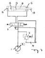
- the hydraulic cylinders 10 and 11 for example, the Lifting cylinders of a hydraulic excavator can be driven by a hydraulic drive, of the three hydraulic pumps 1, 2 and 3, each with one Regulator R can be regulated.
- the three hydraulic pumps 1, 2 and 3 are over one directional control valve 4, 5 and 6 each connected to the hydraulic cylinders 10 and 11, which are also connected in parallel to each other.
- the directional valves 4, 5 and 6 Through the directional valves 4, 5 and 6 the inlets and outlets of the hydraulic cylinders 10 and 11 separated from the respective pumps 1, 2 and 3 and blocked or with the pump are brought into flow connection, the flow direction is reversible so that the hydraulic cylinders are extended and retracted can be.
- the directional control valves 4, 5 and 6 are controlled by an electronic control device 15 driven to control the movement of the hydraulic cylinders 10 and 11.
- the movement of the hydraulic cylinders 10 and 11 is on the one hand by a position detection device 17 monitors the approach of the piston rod to the indicates both end positions, in particular reaching a pre-end position indicates. On the other hand, by means of a speed detection device 16 detects the speed of the piston rod of the hydraulic cylinders 10 and 11, if they reach the above end position.
- Figure 3 shows a speed detection device 16 in its simplest form.
- the speed is measured in each of the pre-end positions of the piston of the hydraulic cylinder by means of two limit switches S 1 and S 2 or S 3 and S 4 .
- a marking is attached to the piston rod 18, which is detected by the limit switches S 1 to S 4 when the piston rod is moved past it.
- the limit switches can be mechanical switches or inductive sensors.
- the limit switches S 1 to S 4 are assigned a time recording device 19 in the control device 15, which determines the time span that the successively arranged limit switches S 1 and S 2 or S 3 and S 4 take. The time it takes to drive over a pair of limit switches is a measure of the piston speed when the pre-end position is reached.
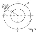
- FIG. 4 shows a simplified solution of a speed detection device 16.
- the limit switches S 1 and S 2 are not arranged directly on the hydraulic cylinder or are not assigned directly to the piston rod 18, but are attached to the pivot point of corresponding equipment parts which are relative to one another by the hydraulic cylinders 10 and 11 be moved.
- the rotary detection disc 20 with a moving part such. B. on the spoon with the bearing block of a hydraulic excavator or be formed by part of the bearing block.
- the limit switches in the form of inductive sensors S 1 and S 2 can with the counterpart, for. B. the arm of the hydraulic excavator.
- the markings 21, 22 are attached to the detection disk 20 such that they reach the limit switches S 1 and S 2 when the hydraulic cylinder reaches one of its pre-end positions.
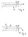
- FIG. 5 Another preferred embodiment of a speed detection device 16 is shown in FIG. 5.
- the path of the piston is detected via markings on the cylinder rod or piston rod 18 and corresponding limit switches or sensors S 1 and S 2 over the complete path of the piston.
- the sensors S 1 and S 2 are located in the unpressurized area of the piston rod bearing.
- Such a relative measuring system is expediently provided with a reference zero which is passed over at least once each time the machine is started.
- the configuration of the position and speed detection device 16 or 17 shown in FIG. 6 is preferred in comparison thereto.
- the path of the piston rod 18 is only detected in the region of the two end positions, which is completely sufficient for hydraulic cylinders in which only the Motion damping according to the invention should take place.
- the limit switches S 1 and S 2 are in turn integrated into the hydraulic cylinder in the region of the piston rod bearing and detect markings on the piston rod 18 which are provided in their end regions. If the markings 21 or 22 reach the limit switches or end signal transmitters S 1 and S 2 , they emit a signal so that, in the manner described above, on the one hand the reaching of the pre-end position of the piston is indicated and on the other hand the speed of the piston is detected or can be determined.
- the control device 15 shown in Figure 1 actuates the directional control valves 4, 5 and 6 Reaching the pre-end positions depending on the speed recorded as follows:
- FIG. 2 shows, a movement of the hydraulic cylinders 10 and 11 is initiated by the control of the directional valves 4, 5 and 6 at point P1.
- the control current is first increased to a 10% value such as 10, so that the start of movement of the hydraulic cylinders can be assumed in point 2.
- the pressure build-up and the acceleration of the hydraulic cylinders 10 and 11 take place along the control ramp between points P2 and P3.
- the hydraulic cylinders reach their maximum speed at 90% control current I 90 , which is reached in point P3 of the diagram in FIG. From there, the maximum current Imax is reached in point P4, so that the hydraulic pistons run at full speed.
- the first end signal generator S 1 is first run over in the direction of movement.
- the hydraulic cylinder is still driven at full speed, the first end signal generator S 1 emitting its signal.
- a control piston of one of the directional control valves 4 or several control pistons of several directional control valves 4 and 5 is abruptly deactivated, so that the corresponding control current for these directional control valves suddenly drops from point P5 to point P6, ie to zero.
- the control pistons follow the current according to their dynamic properties.
- the remaining control pistons continue to be driven with the full control current Imax until the second end signal generator S 2 is also run over and emits its corresponding signal.
- the time t K is determined which was required to drive over both end signal generators S 1 and S 2 .
- a comparison and difference formation device 23 in the control device 15 compares the detected value t K of the time period, which is a measure of the speed of the hydraulic cylinder, with a predetermined value t S. If the detected time t K is less than or equal to the value t S , the damping process takes place along the line between the points P7, P8, P9, P10, P11, P12. This means that the recorded piston speed was greater than or equal to a limit speed. The damping process is initiated immediately.
- the damping takes place with a time delay, specifically along the line between the points P7 ', P8', P9 ', P10', P11 'and P12'.
- the time offset t F is selected by the control device 15 proportional to the time exceeding t S , ie proportional to the amount by which the detected time t K is greater than the predetermined time t S.
- the control current for the remaining directional control valves 6 to n ie for the directional control valves that were not immediately retracted when the first end signal generator S 1 was overrun, is reduced to the grade rule I S.
- the control pistons of the directional control valves are suddenly brought into a position from which a braking effect occurs on the outlet side of the hydraulic cylinders 10 and 11.
- Braking then takes place along the damping ramp from point P8 to Point P9 or from point P8 'to point P9'.
- a piston continues to run along the damping ramp up to the Points P11 or P11 ', where it is then switched off, i.e. the current will reduced to zero, as indicated by points P12 or P12 '.
- the remaining control piston of the one way valve is driven along a control ramp from point P9 to point P10 or P9 'and P10', where it then reaches the outlet current I A at point P10. With the outlet flow it is possible to reach the end position with full cylinder force.
- the cut-off is initiated at point P13 by releasing the hand control.
- the current runs along the jump ramp from point P13 to point P14 and is then turned off along the line from point P14 to point P15.
- n pumps can be used.
Abstract
Description
Die vorliegende Erfindung betrifft ein Verfahren sowie eine Vorrichtung zur Bewegungsdämpfung von Hydraulikzylindern mobiler Arbeitsmaschinen, insbesondere Hydraulikbaggern, wobei mittels einer Stellungserfassungseinrichtung das Erreichen einer Vorendstellung des Hydraulikzylinders erfasst wird, vor dem Erreichen der Endlagen des Hydraulikzylinders dessen Bewegungsgeschwindigkeit reduziert und der Hydraulikzylinder mit nur reduzierter Geschwindigkeit in die jeweilige Endlage gefahren wird. Hierzu ist ein Strömungssteuerorgan zur Drosselung des Zulaufs und/oder des Ablaufs des Hydraulikzylinders vorgesehen, das von einer Steuereinrichtung bei Erreichen der Vorendstellung entsprechend angesteuert wird, um den Mengenstrom zu drosseln, der in den Hydraulikzylinder bzw. aus diesem strömt.The present invention relates to a method and a device for damping movement of hydraulic cylinders of mobile machines, in particular Hydraulic excavators, whereby reaching is achieved by means of a position detection device a pre-end position of the hydraulic cylinder is detected before it is reached the end positions of the hydraulic cylinder reduces its speed of movement and the hydraulic cylinder to the respective end position at a reduced speed is driven. For this purpose there is a flow control element for throttling the inlet and / or the flow of the hydraulic cylinder provided by a Control device is activated accordingly when the pre-end position is reached, in order to throttle the volume flow that flows into and out of the hydraulic cylinder flows.
Die Bewegungsdämpfung bzw. Endlagenabschaltung von Hydraulikzylindern sorgt dafür, dass die Geschwindigkeit der Hydraulikzylinder kurz vor Erreichen des mechanischen Endanschlags reduziert wird, um eine übermäßige mechanische Belastung der Stahlbauteile bedingt durch Massenkräfte durch die schlagartige Verzögerung zu vermeiden und den Komfort während der Arbeit zu erhöhen. Für eine solche Bewegungsdämpfung wurden bereits hydraulische Lösungen als auch elektrische Abschaltungen vorgeschlagen.The damping of movement or end position switch-off of hydraulic cylinders ensures ensure that the speed of the hydraulic cylinder shortly before reaching the mechanical End stop is reduced to excessive mechanical stress of the steel components due to mass forces caused by the sudden deceleration to avoid and increase comfort during work. For one Such motion damping have been hydraulic as well as electrical solutions Shutdowns suggested.
Eine hydraulische Lösung zeigt Figur 7. Wie darin gezeigt ist, erfolgt der Antrieb
von Hydraulikzylindern von Erdbearbeitungsmaschinen wie Hydraulikbaggern und
dergleichen regelmäßig über eine Hydraulikpumpe 1 und ein nachgeschaltetes
Wegeventil 4. Im Hydraulikzylinder 10 sind im Endbereich von Kolben und Stange
geometrische Veränderungen 13 angebracht, die beim Eintritt in die veränderte
Geometrie 12 des Zylindergehäuses einen Druckstau des rücklaufenden Fluids
bewirken.Figure 7 shows a hydraulic solution. As shown therein, the drive takes place
of hydraulic cylinders of earth-working machines such as hydraulic excavators and
the like regularly via a
Die Geschwindigkeit des Zylinders wird über die Fördermenge der Hydraulikpumpe
1 im Zulauf zum Zylinder bestimmt. Eine Dämpfungswirkung entsteht nur dann,
wenn die Menge im Zulauf zum Zylinder reduziert wird. Eine Reduzierung kann
hierbei nur dadurch erreicht werden, indem entweder der Regler R der Pumpe 1
oder ein in den Hydraulikkreis geschaltetes Überdruckventil 7 anspricht. Das Ansprechen
des Pumpenreglers bzw. des Überdruckventils wird dabei durch den Zulaufdruck
erreicht, was bedeutet, dass der Staudruck auf der Ablaufseite entsprechend
des Übersetzungsverhältnisses des Hydraulikzylinders ansteigen muss. Das
Ansprechen des Druckreglers der Pumpe bzw. des Überdruckventils erfolgt je nach
Maschinengröße zwischen 300 und 350 Bar Druck, so dass auf der Zulaufseite des
Hydraulikzylinders ein Staudruck von 600 bis 700 Bar erforderlich ist.The speed of the cylinder is determined by the delivery rate of the
Der Staudruck wird über eine Drosselung am Ringspalt und speziellen Drosselquerschnitten erreicht, wobei die Drosselwirkung am Ringspalt stark abhängig von den Fertigungstoleranzen und der Viskosität des Fluids ist. Aufgrund dieser Abweichungen von Geometrie- und Fluidkenngrößen ist die Wahrscheinlichkeit groß, dass entweder der Staudruck nicht ausreicht, um die Regelorgane zu aktivieren, oder dass der Staudruck so hoch ansteigt, dass die Festigkeit des Zylindergehäuses gefährdet wird. The dynamic pressure is reduced by throttling at the annular gap and special throttle cross sections reached, the throttling effect at the annular gap strongly dependent on the manufacturing tolerances and the viscosity of the fluid. Because of these deviations of geometry and fluid parameters the probability is high that either the dynamic pressure is not sufficient to activate the regulating elements, or that the dynamic pressure rises so high that the strength of the cylinder housing is at risk.
Aufgrund dieser Unzulänglichkeiten wurde bereits eine elektrische Abschaltung des Zu- und Ablaufs vorgeschlagen. Bei Systemen mit elektrohydraulischer Vorsteuerung bietet sich eine elektrische Abschaltung an, bei der ein Endschalter pro Bewegungsrichtung des Zylinders vorgesehen ist. Kurz vor Erreichen der Endlage des Zylinders wird ein entsprechender Endschalter überfahren, durch dessen Signal die Steuereinrichtung das entsprechende Wegeventil abschaltet. Es erfolgt hierdurch ein Bremsen der Bewegung in Abhängigkeit der Schaltgeschwindigkeit des Wegeventils.Because of these shortcomings, an electrical shutdown of the Inlet and outlet proposed. For systems with electro-hydraulic pilot control offers an electrical shutdown, with one limit switch per direction of movement of the cylinder is provided. Shortly before the end position of the A corresponding limit switch is passed over the cylinder, with the signal of which the Control device switches off the corresponding directional valve. It does so braking of the movement depending on the switching speed of the directional valve.
Bei dieser Lösung wird jedoch regelmäßig zu früh oder zu spät angehalten, was einerseits bedeutet, dass die Kinematik nicht vollständig ausgenützt wird oder doch der mechanische Endanschlag des Hydraulikzylinders mit zu hoher Geschwindigkeit erreicht wird. Bei unkontrolliertem Abschalten entstehen zudem Druckspitzen auf der Ablaufseite und Füllungsmangel auf der Zulaufseite, welche zur erhöhten Belastung der Leitungen und Hydraulikkomponenten führen.With this solution, however, what is stopped regularly too early or too late on the one hand means that the kinematics is not fully used or at least the mechanical end stop of the hydraulic cylinder at too high a speed is achieved. In the event of an uncontrolled shutdown, pressure peaks also occur on the outlet side and lack of filling on the inlet side, which leads to increased Load the lines and hydraulic components.
Der vorliegenden Erfindung liegt daher die Aufgabe zugrunde, ein verbessertes Verfahren sowie eine verbesserte Vorrichtung zur Bewegungsdämpfung von Hydraulikzylindern der jeweils eingangs genannten Art zu schaffen, die Nachteile des Standes der Technik vermeiden und letzteren in vorteilhafter Weise weiterbilden. Vorzugsweise soll ein Auffahren auf den mechanischen Endanschlag mit zu hoher Geschwindigkeit sicher vermieden und dabei dennoch die Kinematik des Hydraulikzylinders vollständig ausgenutzt werden.The present invention is therefore based on the object of an improved Method and an improved device for damping the movement of hydraulic cylinders to create the disadvantages of Avoid prior art and further develop the latter in an advantageous manner. Preferably, the mechanical end stop should be driven too high Speed safely avoided while still maintaining the kinematics of the hydraulic cylinder be fully exploited.
Erfindungsgemäß wird diese Aufgabe durch ein Verfahren gemäß Patentanspruch
1 sowie eine Vorrichtung gemäß Patentanspruch 7 gelöst. Bevorzugte Ausgestaltungen
der Erfindung sind Gegenstand der Unteransprüche.According to the invention, this object is achieved by a method according to the
Es ist also erfindungsgemäß eine Geschwindigkeitserfassungseinrichtung vorgesehen, die die Bewegungsgeschwindigkeit des Hydraulikzylinders vor Erreichen der jeweiligen Endlage erfasst. Die Steuereinrichtung, die das Strömungssteuerorgan zur Drosselung des Zulaufs bzw. Ablaufs ansteuert, umfasst eine Verzögerungseinrichtung, mit Hilfe derer der Anfangszeitpunkt der Drosselung in Abhängigkeit der erfassten Bewegungsgeschwindigkeit verändert wird.According to the invention, a speed detection device is therefore provided, which the speed of movement of the hydraulic cylinder before reaching the respective end position recorded. The control device, which is the flow control element controls for throttling the inflow or outflow comprises a delay device, with the help of which the start time of the throttling depending on the detected movement speed is changed.
Das Strömungssteuerorgan wird also je nach erfasster Bewegungsgeschwindigkeit des Hydraulikzylinders früher oder später betätigt, so dass die Bewegungsdämpfung bzw. Geschwindigkeitsreduzierung des Hydraulikzylinders früher oder später einsetzt. Dabei kann die Bewegungsdämpfung insbesondere derart an die Bewegungsgeschwindigkeit angepasst werden, dass einerseits das Erreichen des mechanischen Endanschlages erfolgt, andererseits das Erreichen des Endanschlages jedoch nur mit der gewünschten Minimalgeschwindigkeit erfolgt.The flow control element is therefore dependent on the detected speed of movement of the hydraulic cylinder actuated sooner or later, so that the movement damping or speed reduction of the hydraulic cylinder sooner or later starts. The movement damping can in particular be related to the speed of movement be adjusted so that on the one hand reaching the mechanical End stop occurs, on the other hand reaching the end stop but only at the desired minimum speed.
Um die Bewegungsdämpfung an die erfasste Geschwindigkeit anzupassen, könnte grundsätzlich die Drosselgeschwindigkeit des Strömungsorgans, d.h. die Geschwindigkeit, mit der der Mengenstrom heruntergefahren wird, verändert werden. Um eine einfache Steuerung zu erlauben, ist in Weiterbildung der Erfindung jedoch vorzugsweise vorgesehen, dass die Drosselgeschwindigkeit des Strömungssteuerorgans unabhängig von der erfassten Bewegungsgeschwindigkeit des Hydraulikzylinders vorgegeben wird. Die Anpassung der Bewegungsdämpfung wird also allein dadurch erreicht, dass der Anfangszeitpunkt der Drosselung bzw. der Betätigungszeitpunkt des Strömungssteuerorgans in Abhängigkeit der erfassten Geschwindigkeit verschoben wird. Allerdings ist es hier durchaus möglich, bei Verwendung mehrerer Strömungssteuerorgane die Betätigungszeitpunkte der Steuerorgane unterschiedlich zu verschieben, so dass sich insgesamt eine unterschiedliche Dämpfungscharakteristik ergibt. Allerdings kann auch hier für jedes der Steuerorgane die Drosselgeschwindigkeit an sich gleichgehalten werden.In order to adapt the motion damping to the recorded speed, basically the throttle speed of the flow element, i.e. the speed, with which the volume flow is shut down can be changed. In order to allow simple control, however, is a further development of the invention preferably provided that the throttle speed of the flow control member regardless of the detected movement speed of the hydraulic cylinder is specified. The adjustment of the motion damping becomes alone thereby achieved that the start time of the throttling or the actuation time of the flow control element as a function of the detected speed is moved. However, it is quite possible here if several are used Flow control elements the actuation times of the control elements different to shift, so that there is a different damping characteristic overall results. However, here too, for each of the tax bodies Throttle speed per se are kept the same.
Zweckmäßigerweise wird der Dämpfungsbeginn mit abnehmender Bewegungsgeschwindigkeit des Hydraulikzylinders verzögert, d.h. zeitlich nach hinten hinaus geschoben.The start of damping is expedient with decreasing movement speed of the hydraulic cylinder is delayed, i.e. pushed back in time.
Die Anpassung des Anfangszeitpunkts der Dämpfung an die Bewegungsgeschwindigkeit kann grundsätzlich in verschiedener Art und Weise erfolgen. Um die Steuerungsanordnung jedoch einfach zu halten, ist in Weiterbildung der Erfindung die Steuereinrichtung derart ausgebildet, dass ein fester Anfangszeitpunkt immer dann vorgegeben wird, wenn die erfasste Bewegungsgeschwindigkeit größer oder gleich einer vorgegebenen Grenzgeschwindigkeit ist, d.h. also die von der Kolbenstellungserfassungseinrichtung erfasste Vorendstellung mit einer Grenzgeschwindigkeit oder einer noch größeren Geschwindigkeit überfahren wird. In diesem Fall wird die Dämpfung unmittelbar eingeleitet. Liegt die in der Vorendstellung erfasste Bewegungsgeschwindigkeit jedoch unter der Grenzgeschwindigkeit, wird der Anfangszeitpunkt der Dämpfung um eine gewisse Zeitspanne verzögert. Die Zeitspanne, um die der Anfangszeitpunkt der Dämpfung bzw. der Zeitpunkt der Betätigung des Strömungssteuerorgans verschoben wird, kann durch die Steuereinrichtung variabel festgelegt werden. Vorzugsweise verändert die Steuereinrichtung die Zeitspanne, um die die Dämpfung verschoben wird, proportional zu der erfassten Geschwindigkeit bei Erreichen der Vorendstellung.The adaptation of the starting time of the damping to the speed of movement can basically be done in different ways. To the control arrangement however, to keep it simple, is in the development of the invention Control device designed such that a fixed start time then always is specified if the detected movement speed is greater than or equal to is a predetermined limit speed, i.e. So that of the piston position detection device detected final position with a limit speed or at an even greater speed. In this case the damping initiated immediately. Is the movement speed recorded in the pre-end position however, below the limit speed, the starting time damping delayed by a certain period of time. The timespan, around the start of the damping or the time of actuation of the flow control member can be moved by the control device can be set variably. The control device preferably changes the Time span by which the damping is shifted, proportional to the detected one Speed when reaching the pre-end position.
Die Geschwindigkeitserfassungseinrichtung kann in Weiterbildung der Erfindung zwei hintereinander angeordnete Endsignalgeber aufweisen, die kurz vor Erreichen der Endstellung des Kolbens überfahren werden, sowie eine Zeiterfassungseinrichtung umfassen, die die Zeitspanne zwischen den Signalen der beiden Endsignalgeber erfasst. Das Signal der Zeiterfassungseinrichtung, das die genannte Zeitspanne zwischen den Signalen der beiden Endsignale wiedergibt, bildet das Geschwindigkeitssignal, das die Steuereinrichtung der Ansteuerung des Strömungssteuerorgans zugrundelegt.In a further development of the invention, the speed detection device can have two end signal generators arranged one behind the other, which shortly before reaching the end position of the piston are run over, and a time recording device comprise the time span between the signals of the two end signal generators detected. The signal of the time recording device that the said period of time reproduces between the signals of the two end signals, forms the speed signal, that the control device of the control of the flow control member based sets.
Die erfasste Zeitspanne, die das Überfahren der beiden hintereinander angeordneten Endsignalgeber dauert, wird sodann in einer Vergleichseinrichtung der Steuereinrichtung mit einer vorgegebenen Zeitspanne verglichen. Ist die Differenz negativ, d.h. die erfasste Zeit kleiner als die vorgegebene Zeit, wird der feste, frühest mögliche Anfangszeitpunkt der Dämpfung von der Steuereinrichtung bestimmt. Ist die Differenz positiv, d.h. die erfasste Zeit größer als die vorgegebene Zeit, wird der Betrag der Differenz der Verzögerung des Dämpfungsbeginns zugrundegelegt. Insbesondere kann der Anfangszeitpunkt um den Betrag der bestimmten Differenz nach hinten verschoben werden.The time span recorded, the crossing of the two arranged one behind the other End signal generator lasts, is then in a comparison device of the control device compared with a predetermined period of time. If the difference is negative, i.e. the recorded time is less than the specified time, the fixed earliest possible starting time of the damping determined by the control device. is the difference is positive, i.e. the recorded time is greater than the specified time, the Amount of the difference between the delay in the start of damping. In particular the starting time can be determined by the amount of the difference be moved backwards.
Die Geschwindigkeitserfassungseinrichtung bzw. deren Endsignalgeber können grundsätzlich an verschiedener Stelle angeordnet und dem Hydraulikzylinder zugeordnet sein. Um eine einfache Anordnung zu schaffen und für beide Endstellungen nur ein Paar Endsignalgeber vorsehen zu müssen, können an der Kolbenstange des Hydraulikzylinders und/oder einem damit gekoppelten Detektionsgeber erste und zweite Markierungen vorgesehen sein, die jeweils einer der beiden Endstellungen bzw. Vorendstellungen des Kolbens entsprechen. Beide Markierungen können von einem entsprechend angeordneten Endsignalgeberpaar erfasst werden. Es ist dementsprechend nur eine Erfassungseinrichtung zur Erfassung beider Endstellungen bzw. nur eine Erfassungseinrichtung zur Erfassung der Geschwindigkeit bei Erreichen beider Endstellungen vorgesehen.The speed detection device or its end signal generator can basically arranged at different locations and assigned to the hydraulic cylinder his. To create a simple arrangement and for both end positions only one pair of end signal transmitters can be provided on the piston rod of the hydraulic cylinder and / or a detection sensor coupled to it first and second markings can be provided, each one of the two end positions or pre-end positions of the piston. Both marks can are detected by a correspondingly arranged pair of end signal transmitters. It is accordingly only one detection device for detecting both end positions or only one detection device for detecting the speed Reaching both end positions provided.
Die Erfassungseinrichtungen können vorzugsweise in den Hydraulikzylinder integriert sein, insbesondere im Bereich des Kragens des Hydraulikzylinders angeordnet sein, durch den die Kolbenstange austritt.The detection devices can preferably be integrated in the hydraulic cylinder be arranged in particular in the region of the collar of the hydraulic cylinder through which the piston rod exits.
Gemäß einer besonders vorteilhaften Ausführung der Erfindung kann auch ein vom Hydraulikzylinder separater, mit diesem jedoch gekoppelter Detektionsgeber vorgesehen sein, der sich entsprechend der Bewegung des Hydraulikzylinders bewegt. Insbesondere kann hier eine rotatorische Drehscheibe vorgesehen sein, die zwei Markierungen der vorgenannten Art aufweist. Die Stellung der Markierungen können durch entsprechende Endsignalgeber erfasst werden.According to a particularly advantageous embodiment of the invention, one of Hydraulic cylinder separate, but with this coupled detection transmitter provided be that moves according to the movement of the hydraulic cylinder. In particular, a rotary turntable can be provided here, the two Has markings of the aforementioned type. The position of the markings can be detected by appropriate end signal transmitters.
Die Erfindung wird nachfolgend anhand bevorzugter Ausführungsbeispiele und zugehöriger Zeichnungen näher erläutert. In den Zeichnungen zeigen:
- Fig. 1:
- eine schematische Darstellung eines hydraulischen Antriebssystems für zwei Hydraulikzylinder eines Hydraulikbaggers mit einer Vorrichtung zur Bewegungsdämpfung nach einer vorteilhaften Ausführung der vorliegenden Erfindung, wobei das Antriebssystem als Dreipumpensystem dargestellt ist,
- Fig. 2:
- ein Stromzeitdiagramm, das den Verlauf des Ansteuerstroms für die Wegeventile des hydraulischen Antriebs aus Fig. 1 zur Erreichung der gewünschten Bewegungsdämpfung zeigt,
- Fig. 3:
- die Anordnung der Endsignalgeber zur Erfassung einer Vorendstellung und Geschwindigkeit des Kolbens des Hydraulikzylinders nach einer Ausführung der Erfindung, bei der vier Endsignalgeber vorgesehen sind, die eine Markierung an der Kolbenstange erfassen,
- Fig. 4:
- eine schematische Darstellung einer mit der Kolbenstange des Hydraulikzylinders gekoppelten Detektionsscheibe sowie die zugehörige Anordnung der Endsignalgeber einer Erfassungseinrichtung zur Erfassung der Vorendstellung und der Geschwindigkeit des Hydraulikzylinders für beide Bewegungsrichtungen,
- Fig. 5:
- eine schematische Darstellung einer in den Hydraulikzylinder integrierten Einrichtung zur Erfassung der Kolbenstellung und der Kolbengeschwindigkeit,
- Fig. 6:
- eine schematische Darstellung einer in den Hydraulikzylinder integrierten Einrichtung zur Erfassung der Vorendstellung und der Geschwindigkeit des Kolbens des Hydraulikzylinders nach einer weiteren Ausführung der Erfindung, und
- Fig. 7:
- eine schematische Darstellung eines hydraulischen Einpumpenantriebs eines Hydraulikzylinders mit hydraulischer Bewegungsdämpfung nach dem Stand der Technik.
- Fig. 1:
- 1 shows a schematic representation of a hydraulic drive system for two hydraulic cylinders of a hydraulic excavator with a device for damping movement according to an advantageous embodiment of the present invention, the drive system being shown as a three-pump system,
- Fig. 2:
- 1 shows a current-time diagram which shows the course of the control current for the directional control valves of the hydraulic drive from FIG. 1 in order to achieve the desired movement damping,
- Fig. 3:
- the arrangement of the end signal transmitters for detecting a pre-end position and speed of the piston of the hydraulic cylinder according to an embodiment of the invention, in which four end signal transmitters are provided which detect a marking on the piston rod,
- Fig. 4:
- 1 shows a schematic illustration of a detection disk coupled to the piston rod of the hydraulic cylinder and the associated arrangement of the end signal transmitters of a detection device for detecting the pre-end position and the speed of the hydraulic cylinder for both directions of movement,
- Fig. 5:
- 1 shows a schematic representation of a device integrated in the hydraulic cylinder for detecting the piston position and the piston speed,
- Fig. 6:
- is a schematic representation of a device integrated in the hydraulic cylinder for detecting the pre-end position and the speed of the piston of the hydraulic cylinder according to a further embodiment of the invention, and
- Fig. 7:
- is a schematic representation of a hydraulic pump drive of a hydraulic cylinder with hydraulic motion damping according to the prior art.
Wie Figur 1 zeigt, werden die Hydraulikzylinder 10 und 11, die beispielsweise die
Hubzylinder eines Hydraulikbaggers sein können, von einem Hydraulikantrieb angetrieben,
der drei Hydraulikpumpen 1, 2 und 3 aufweist, die jeweils über einen
Regler R geregelt werden können. Die drei Hydraulikpumpen 1, 2 und 3 sind über
jeweils ein Wegeventil 4, 5 und 6 mit den Hydraulikzylindern 10 und 11 verbunden,
die ebenfalls parallel zueinander geschaltet sind. Durch die Wegeventile 4, 5 und 6
können in an sich bekannter Weise die Zu- und Abläufe der Hydraulikzylinder 10
und 11 von den jeweiligen Pumpen 1, 2 und 3 abgetrennt und abgesperrt oder mit
der Pumpe in Strömungsverbindung gebracht werden, wobei die Strömungsrichtung
umkehrbar ist, so dass die Hydraulikzylinder ausgefahren und eingefahren
werden können. Stromauf der Wegeventile 4, 5 und 6 sind in die von den Pumpen
1, 2 und 3 abgehenden Druckleitungen Überdruckventile 7, 8 und 9 geschaltet, über
die Hydraulikfluid in den Tank 14 abgelassen werden kann. Auch die Wegeventile
4, 5 und 6 sind über entsprechende Leitungen mit dem Tank 14 verbunden, um
in der abgesperrten Stellung das von der Pumpe geförderte Fluid sowie bei entsprechender
Schaltstellung von den Hydraulikzylindern zurücklaufendes Fluid in
den Tank zu führen.As Figure 1 shows, the
Die Wegeventile 4, 5 und 6 werden von einer elektronischen Steuereinrichtung 15
angesteuert, um die Bewegung der Hydraulikzylinder 10 und 11 zu steuern.The directional control valves 4, 5 and 6 are controlled by an
Die Bewegung der Hydraulikzylinder 10 und 11 wird einerseits von einer Stellungserfassungseinrichtung
17 überwacht, die die Annäherung der Kolbenstange an deren
beiden Endstellungen anzeigt, insbesondere das Erreichen einer Vorendstellung
angibt. Andererseits wird mittels einer Geschwindigkeitserfassungseinrichtung
16 die Geschwindigkeit der Kolbenstange der Hydraulikzylinder 10 und 11 erfasst,
wenn diese die genannte Vorendstellung erreichen.The movement of the
Die Geschwindigkeitserfassung und die Erfassung der Vorendstellung kann in verschiedener
Art und Weise erfolgen. Figur 3 zeigt eine Geschwindigkeitserfassungseinrichtung
16 in einfachster Form. Dabei erfolgt die Geschwindigkeitserfassung in
jeder der Vorendstellungen des Kolbens der Hydraulikzylinder mittels zweier Endschalter
S1 und S2 bzw. S3 und S4. An der Kolbenstange 18 ist eine Markierung angebracht,
die von den Endschaltern S1 bis S4 erfasst wird, wenn die Kolbenstange
daran vorbeibewegt wird. Die Endschalter können mechanische Schalter oder Induktivgeber
sein. Den Endschaltern S1 bis S4 ist eine Zeiterfassungseinrichtung 19
in der Steuereinrichtung 15 zugeordnet, die die Zeitspanne bestimmt, die das
Überfahren der nacheinander angeordneten Endschalter S1 und S2 bzw. S3 und S4
dauert. Die Zeit, die das Überfahren eines Endschalterpaares dauert, ist ein Maß
für die Kolbengeschwindigkeit bei Erreichen der Vorendstellung.The speed detection and the detection of the pre-end position can be done in different ways. Figure 3 shows a
Eine vereinfachte Lösung einer Geschwindigkeitserfassungseinrichtung 16 zeigt
Figur 4. Hierbei sind die Endschalter S1 und S2 nicht direkt am Hydraulikzylinder
angeordnet bzw. nicht direkt der Kolbenstange 18 zugeordnet, sondern sind am
Drehpunkt entsprechender Ausrüstungsteile angebracht, die von den Hydraulikzylindern
10 und 11 relativ zueinander bewegt werden. Beispielsweise kann die rotatorische
Detektionsscheibe 20 mit einem bewegten Teil wie z. B. am Löffel mit dem
Lagerbock eines Hydraulikbaggers verbunden sein bzw. von einem Teil des Lagerbocks
gebildet sein. Die Endschalter in Form von Induktivgebern S1 und S2 können
mit dem Gegenstück, z. B. dem Stiel des Hydraulikbaggers, verbunden sein. Die
Markierungen 21, 22 sind derart an der Detektionsscheibe 20 angebracht, dass sie
die Endschalter S1 und S2 erreichen, wenn der Hydraulikzylinder jeweils eine seiner
Vorendstellungen erreicht.FIG. 4 shows a simplified solution of a
Eine weitere bevorzugte Ausführungsform einer Geschwindigkeitserfassungseinrichtung
16 zeigt Figur 5. Bei dieser Ausführung wird der Weg des Kolbens über
Markierungen an der Zylinderstange bzw. Kolbenstange 18 und entsprechenden
Endschaltern bzw. Sensoren S1 und S2 über den kompletten Weg des Kolbens erfasst.
Die Sensoren S1 und S2 befinden sich im drucklosen Bereich des Kolbenstangenlagers.
Ein solches relatives Messsystem ist zweckmäßigerweise mit einer
Referenznull versehen, die bei jedem Start der Maschine mindestens einmal überfahren
wird. Another preferred embodiment of a
Für die vorliegende Bewegungsdämpfung bevorzugt ist im Vergleich dazu die in
Figur 6 gezeigte Ausbildung der Stellungs- und Geschwindigkeitserfassungseinrichtung
16 bzw. 17. Der Weg der Kolbenstange 18 wird nur im Bereich der beiden
Endlagen erfasst, was völlig ausreichend ist für Hydraulikzylinder, bei denen nur die
erfindungsgemäße Bewegungsdämpfung stattfinden soll. Die Endschalter S1 und
S2 sind wiederum im Bereich des Kolbenstangenlagers in den Hydraulikzylinder
integriert und erfassen Markierungen auf der Kolbenstange 18, die in deren Endbereichen
vorgesehen sind. Erreichen die Markierungen 21 bzw. 22 die Endschalter
bzw. Endsignalgeber S1 und S2, geben diese ein Signal ab, so dass in der zuvor
beschriebenen Weise zum einen das Erreichen der Vorendstellung des Kolbens
angezeigt und andererseits die dabei vorhandene Geschwindigkeit des Kolbens
erfasst bzw. bestimmt werden kann.For the present movement damping, the configuration of the position and
Die in Figur 1 gezeigte Steuereinrichtung 15 betätigt die Wegeventile 4, 5 und 6 bei
Erreichen der Vorendstellungen in Abhängigkeit der dabei erfassten Geschwindigkeit
folgendermaßen:The
Wie Figur 2 zeigt, wird eine Bewegung der Hydraulikzylinder 10 und 11 durch die
Ansteuerung der Wegeventile 4, 5 und 6 im Punkt P1 eingeleitet. Der Ansteuerstrom
wird zunächst auf einen 10%igen Wert wie 10 erhöht, so dass der Bewegungsbeginn
der Hydraulikzylinder im Punkt 2 angenommen werden kann. Der
Druckaufbau und die Beschleunigung der Hydraulikzylinder 10 und 11 erfolgt entlang
der Steuerrampe zwischen den Punkten P2 und P3. Die Hydraulikzylinder erreichen
ihre Maximalgeschwindigkeit bei 90%igem Ansteuerstrom I90, der im Punkt
P3 des Diagramms aus Figur 2 erreicht wird. Von dort wird auf den Maximalstrom
Imax in Punkt P4 gegangen, so dass die Hydraulikkolben mit voller Geschwindigkeit
fahren.As FIG. 2 shows, a movement of the
Wird der Kolben dementsprechend bis zu einer seiner Endstellungen gefahren, wird zunächst der in Bewegungsrichtung erste Endsignalgeber S1 überfahren. Im Diagramm Punkt P5 gemäß Figur 2 wird der Hydraulikzylinder noch mit voller Geschwindigkeit gefahren, wobei der erste Endsignalgeber S1 sein Signal abgibt. Hier wird je nach Ausrüstungskomponente ein Steuerkolben eines der Wegeventile 4 oder auch mehrere Steuerkolben mehrerer Wegeventile 4 und 5 schlagartig abgesteuert, so dass der entsprechende Ansteuerstrom für diese Wegeventile sprungartig vom Punkt P5 auf Punkt P6, d.h. auf Null fällt. Die Steuerkolben folgen dabei dem Strom entsprechend Ihrer dynamischen Eigenschaft.If the piston is moved accordingly to one of its end positions, the first end signal generator S 1 is first run over in the direction of movement. In the diagram point P5 according to FIG. 2, the hydraulic cylinder is still driven at full speed, the first end signal generator S 1 emitting its signal. Depending on the equipment component, a control piston of one of the directional control valves 4 or several control pistons of several directional control valves 4 and 5 is abruptly deactivated, so that the corresponding control current for these directional control valves suddenly drops from point P5 to point P6, ie to zero. The control pistons follow the current according to their dynamic properties.
Die verbleibenden Steuerkolben werden weiter mit zunächst vollem Ansteuerstrom
Imax angesteuert, bis auch der zweite Endsignalgeber S2 überfahren wird und sein
entsprechendes Signal abgibt. In der Zeiterfassungseinrichtung 19 der Steuereinrichtung
15 wird dabei die Zeit tK bestimmt, die zum Überfahren beider Endsignalgeber
S1 und S2 benötigt wurde. Eine Vergleichs- und Differenzbildungseinrichtung
23 in der Steuereinrichtung 15 vergleicht den erfassten Wert tK der Zeitspanne, der
ein Maß für die Geschwindigkeit des Hydraulikzylinders ist, mit einem vorgegebenen
Wert tS. Ist die erfasste Zeit tK kleiner oder gleich dem Wert tS, so erfolgt der
Dämpfungsvorgang entlang der Linie zwischen den Punkten P7, P8, P9, P10, P11,
P12. Dies bedeutet, dass die erfasste Kolbengeschwindigkeit größer oder gleich
einer Grenzgeschwindigkeit war. Der Dämpfungsvorgang wird unmittelbar eingeleitet.The remaining control pistons continue to be driven with the full control current Imax until the second end signal generator S 2 is also run over and emits its corresponding signal. In the
Ist die erfasste Zeit tK jedoch größer als der vorgegebene Wert tS, so erfolgt die
Dämpfung zeitversetzt, und zwar entlang der Linie zwischen den Punkten P7', P8',
P9', P10', P11' und P12'. Der Zeitversatz tF wird von der Steuereinrichtung 15 dabei
proportional zur zeitlichen Überschreitung von tS, d.h. proportional zu dem Betrag
gewählt, um den die erfasste Zeit tK größer als die vorgegebene Zeit tS ist.However, if the detected time t K is greater than the predetermined value t S , the damping takes place with a time delay, specifically along the line between the points P7 ', P8', P9 ', P10', P11 'and P12'. The time offset t F is selected by the
Der nicht verzögerte Dämpfungsvorgang entlang der Linie zwischen den Punkten P7 und P12 sowie der zeitverzögerte Dämpfungsvorgang entlang der Linie zwischen den Punkten P7' bis P12' kann wie folgt beschrieben werden:The non-delayed damping process along the line between the points P7 and P12 and the time-delayed damping process along the line between points P7 'to P12' can be described as follows:
Zunächst wird der Ansteuerstrom für die verbleibenden Wegeventile 6 bis n, d.h. für
die Wegeventile, die nicht gleich bei Überfahren des ersten Endsignalgebers S1
zurückgefahren wurden, auf den Sprungwert IS zurückgefahren. Durch den Sprung
werden die Steuerkolben der Wegeventile schlagartig in eine Position gebracht, ab
der eine Bremswirkung auf der Ablaufseite der Hydraulikzylinder 10 und 11 erfolgt.First, the control current for the remaining directional control valves 6 to n, ie for the directional control valves that were not immediately retracted when the first end signal generator S 1 was overrun, is reduced to the grade rule I S. As a result of the jump, the control pistons of the directional control valves are suddenly brought into a position from which a braking effect occurs on the outlet side of the
Das Bremsen erfolgt dann entlang der Dämpfungsrampe von dem Punkt P8 zum Punkt P9 bzw. vom Punkt P8' zum Punkt P9'. Je nach Anzahl der verbleibenden Steuerkolben läuft ein Kolben entlang der Dämpfungsrampe weiter bis zu den Punkten P11 bzw. P11', wo er dann jeweils abgeschaltet wird, d.h. der Strom wird zurückgefahren auf Null, wie dies die Punkte P12 bzw. P12' angeben.Braking then takes place along the damping ramp from point P8 to Point P9 or from point P8 'to point P9'. Depending on the number of remaining A piston continues to run along the damping ramp up to the Points P11 or P11 ', where it is then switched off, i.e. the current will reduced to zero, as indicated by points P12 or P12 '.
Der noch verbleibende Steuerkolben des einen Wegeventils wird entlang einer Steuerrampe vom Punkt P9 zum Punkt P10 bzw. P9' und P10' angesteuert, wo er dann in Punkt P10 den Auslaufstrom IA erreicht. Mit dem Auslaufstrom ist ein Erreichen der Endposition bei voller Zylinderkraft möglich.The remaining control piston of the one way valve is driven along a control ramp from point P9 to point P10 or P9 'and P10', where it then reaches the outlet current I A at point P10. With the outlet flow it is possible to reach the end position with full cylinder force.
Die Absteuerung wird bei Punkt P13 durch Loslassen des Handsteuergebers eingeleitet. Der Strom verläuft entlang der Sprungrampe vom Punkt P13 zum Punkt P14 und wird dann abgeschaltet entlang der Linie vom Punkt P14 zum Punkt P15.The cut-off is initiated at point P13 by releasing the hand control. The current runs along the jump ramp from point P13 to point P14 and is then turned off along the line from point P14 to point P15.
Es versteht sich, dass der Dämpfungsvorgang in die Gegenrichtung nach dem gleichen Schema abläuft. Die Detektion und Richtungserkennung erfolgt in umgekehrter Richtung.It is understood that the damping process in the opposite direction after the same Scheme expires. The detection and direction detection takes place in reverse Direction.
Wird anstelle der drei Pumpen 1, 2 und 3 nur eine Pumpe zur Speisung der Hydraulikzylinder
verwendet, versteht es sich, dass bei Überfahren des ersten Endsignalgebers
S1 der Steuerkolben des entsprechenden Wegeventils noch nicht abgeschaltet
wird. Das Gesamtprozedere erfolgt dann geschwindigkeitsabhängig ab
dem Überfahren des zweiten Endsignalgebers S2. Es können grundsätzlich n Pumpen
verwendet werden.If instead of the three
Claims (14)
Applications Claiming Priority (2)
| Application Number | Priority Date | Filing Date | Title |
|---|---|---|---|
| DE10256923 | 2002-12-05 | ||
| DE10256923A DE10256923B4 (en) | 2002-12-05 | 2002-12-05 | Method and device for motion damping of hydraulic cylinders of mobile machines |
Publications (2)
| Publication Number | Publication Date |
|---|---|
| EP1426499A1 true EP1426499A1 (en) | 2004-06-09 |
| EP1426499B1 EP1426499B1 (en) | 2006-12-27 |
Family
ID=32309007
Family Applications (1)
| Application Number | Title | Priority Date | Filing Date |
|---|---|---|---|
| EP03021744A Expired - Lifetime EP1426499B1 (en) | 2002-12-05 | 2003-09-25 | Method and apparatus for end stroke dampening in hydraulic actuators of mobile working machines |
Country Status (7)
| Country | Link |
|---|---|
| US (1) | US7318292B2 (en) |
| EP (1) | EP1426499B1 (en) |
| JP (1) | JP4503272B2 (en) |
| KR (1) | KR101073202B1 (en) |
| CN (1) | CN100353078C (en) |
| AT (1) | ATE349578T1 (en) |
| DE (2) | DE10256923B4 (en) |
Cited By (3)
| Publication number | Priority date | Publication date | Assignee | Title |
|---|---|---|---|---|
| WO2014086327A1 (en) * | 2012-12-04 | 2014-06-12 | Komatsu Mining Germany Gmbh | Hydraulic cylinder with end position damping |
| CN104006037A (en) * | 2014-06-06 | 2014-08-27 | 山东中川液压有限公司 | Three-pump type hydraulic excavator oil supply device |
| CN107178116A (en) * | 2017-06-19 | 2017-09-19 | 徐州徐工挖掘机械有限公司 | A kind of excavator walking automatic speed regulation system and excavator |
Families Citing this family (54)
| Publication number | Priority date | Publication date | Assignee | Title |
|---|---|---|---|---|
| JP4114684B2 (en) | 2005-08-11 | 2008-07-09 | コベルコ建機株式会社 | Control device for hydraulic cylinder and work machine equipped with the same |
| US10537671B2 (en) | 2006-04-14 | 2020-01-21 | Deka Products Limited Partnership | Automated control mechanisms in a hemodialysis apparatus |
| US8292594B2 (en) * | 2006-04-14 | 2012-10-23 | Deka Products Limited Partnership | Fluid pumping systems, devices and methods |
| US7799592B2 (en) * | 2006-09-27 | 2010-09-21 | Taiwan Semiconductor Manufacturing Company, Ltd. | Tri-gate field-effect transistors formed by aspect ratio trapping |
| US8491184B2 (en) * | 2007-02-27 | 2013-07-23 | Deka Products Limited Partnership | Sensor apparatus systems, devices and methods |
| US8425471B2 (en) * | 2007-02-27 | 2013-04-23 | Deka Products Limited Partnership | Reagent supply for a hemodialysis system |
| US8357298B2 (en) | 2007-02-27 | 2013-01-22 | Deka Products Limited Partnership | Hemodialysis systems and methods |
| US8393690B2 (en) | 2007-02-27 | 2013-03-12 | Deka Products Limited Partnership | Enclosure for a portable hemodialysis system |
| US20090107335A1 (en) | 2007-02-27 | 2009-04-30 | Deka Products Limited Partnership | Air trap for a medical infusion device |
| US8042563B2 (en) | 2007-02-27 | 2011-10-25 | Deka Products Limited Partnership | Cassette system integrated apparatus |
| KR101861192B1 (en) | 2007-02-27 | 2018-05-28 | 데카 프로덕츠 리미티드 파트너쉽 | Hemodialysis apparatus and methods |
| US8562834B2 (en) | 2007-02-27 | 2013-10-22 | Deka Products Limited Partnership | Modular assembly for a portable hemodialysis system |
| US9028691B2 (en) * | 2007-02-27 | 2015-05-12 | Deka Products Limited Partnership | Blood circuit assembly for a hemodialysis system |
| US20080253911A1 (en) | 2007-02-27 | 2008-10-16 | Deka Products Limited Partnership | Pumping Cassette |
| US8409441B2 (en) | 2007-02-27 | 2013-04-02 | Deka Products Limited Partnership | Blood treatment systems and methods |
| US8771508B2 (en) * | 2008-08-27 | 2014-07-08 | Deka Products Limited Partnership | Dialyzer cartridge mounting arrangement for a hemodialysis system |
| US20100056975A1 (en) * | 2008-08-27 | 2010-03-04 | Deka Products Limited Partnership | Blood line connector for a medical infusion device |
| KR100974275B1 (en) * | 2007-12-17 | 2010-08-06 | 볼보 컨스트럭션 이키프먼트 홀딩 스웨덴 에이비 | shock absorption device and method thereof for excavator |
| US10201647B2 (en) | 2008-01-23 | 2019-02-12 | Deka Products Limited Partnership | Medical treatment system and methods using a plurality of fluid lines |
| US7975410B2 (en) * | 2008-05-30 | 2011-07-12 | Caterpillar Inc. | Adaptive excavation control system having adjustable swing stops |
| US9206589B2 (en) * | 2009-03-31 | 2015-12-08 | Caterpillar Inc. | System and method for controlling machines remotely |
| US20100245129A1 (en) * | 2009-03-31 | 2010-09-30 | Caterpillar Inc. | System and method for identifying machines |
| US10208529B2 (en) | 2009-06-23 | 2019-02-19 | Higher Power Hydraulic Doors, Llc | Tilt-up door |
| CN101666105B (en) * | 2009-07-08 | 2011-08-10 | 北汽福田汽车股份有限公司 | Method for controlling rising velocity of movable arm of excavator, control system and excavator |
| CN102821798A (en) * | 2009-10-30 | 2012-12-12 | 德卡产品有限公司 | Apparatus and method for detecting disconnection of an intravascular access device |
| WO2011114974A1 (en) * | 2010-03-15 | 2011-09-22 | 株式会社小松製作所 | Control device for work machine on construction vehicle and control method |
| DE102010032359A1 (en) * | 2010-07-27 | 2012-02-02 | Robert Bosch Gmbh | Device for speed-dependent end position damping of piston, has measuring device that is formed to measure speed of piston in region of damping chamber |
| KR20120072729A (en) * | 2010-12-24 | 2012-07-04 | 두산인프라코어 주식회사 | Wheel loader comprising hydraulic pumps with different cut-off pressures |
| AU2012259459B2 (en) | 2011-05-24 | 2016-06-02 | Deka Products Limited Partnership | Blood treatment systems and methods |
| US9724458B2 (en) | 2011-05-24 | 2017-08-08 | Deka Products Limited Partnership | Hemodialysis system |
| FR2975774B1 (en) * | 2011-05-25 | 2014-01-17 | Eurocopter France | METHOD FOR DETERMINING THE STATIC EFFORT DEVELOPED BY A SERVOCOMMANDE |
| US8899143B2 (en) * | 2011-06-28 | 2014-12-02 | Caterpillar Inc. | Hydraulic control system having variable pressure relief |
| JP5752526B2 (en) * | 2011-08-24 | 2015-07-22 | 株式会社小松製作所 | Hydraulic drive system |
| US8666610B2 (en) * | 2012-03-15 | 2014-03-04 | Komatsu Ltd. | Work vehicle and method for controlling work vehicle |
| CN102616217B (en) * | 2012-04-16 | 2013-12-11 | 中联重科股份有限公司 | Control method, device and system for folding and unfolding of engineering machine support leg |
| CN103423235B (en) * | 2012-05-23 | 2015-11-25 | 中联重科股份有限公司 | Oil hydraulic cylinder buffer control method, buffer-type hydraulic cylinder control system and hydraulic equipment |
| CN102678663B (en) * | 2012-05-30 | 2015-05-20 | 上海三一重机有限公司 | Oil cylinder for excavator and excavator with cylinder |
| CN102979782B (en) * | 2012-11-07 | 2015-05-20 | 中国航空工业集团公司沈阳发动机设计研究所 | Limiting device for synchronous limit of actuating cylinders |
| KR101471288B1 (en) * | 2013-05-06 | 2014-12-09 | 현대중공업 주식회사 | Swing device of excavator with anti-sliding device |
| CN103644174B (en) * | 2013-12-16 | 2016-04-20 | 中联重科股份有限公司 | The stroke control method of serial oil cylinders, device and system |
| US9617710B2 (en) | 2014-06-18 | 2017-04-11 | Komatsu Ltd. | Work vehicle and method for controlling work vehicle |
| KR101687499B1 (en) * | 2014-09-10 | 2016-12-19 | 가부시키가이샤 고마쓰 세이사쿠쇼 | Work vehicle |
| CN104999695B (en) * | 2015-06-15 | 2016-09-28 | 浙江大学 | A kind of electrohydraulic control system realizing hydraulic press Ultra-Low Speed stable operation |
| KR200485329Y1 (en) | 2015-09-25 | 2017-12-26 | 라온상사 주식회사 | functional chopsticks |
| JP6559529B2 (en) * | 2015-10-06 | 2019-08-14 | 日立建機株式会社 | Construction machinery |
| JP6650471B2 (en) * | 2016-01-29 | 2020-02-19 | 株式会社小松製作所 | Spool valve device for hydraulic cylinder |
| GB2553504A (en) * | 2016-08-26 | 2018-03-14 | Caterpillar Inc | A machine comprising a body and an implement movable relative to the body |
| JP6697361B2 (en) * | 2016-09-21 | 2020-05-20 | 川崎重工業株式会社 | Hydraulic excavator drive system |
| CN109210036B (en) * | 2018-10-16 | 2020-07-07 | 武汉深能环保新沟垃圾发电有限公司 | Hydraulic system coordination control method, system, equipment and storage medium |
| JP7305968B2 (en) * | 2019-01-28 | 2023-07-11 | コベルコ建機株式会社 | Driving device for hydraulic cylinders in working machines |
| US11408449B2 (en) | 2019-09-27 | 2022-08-09 | Topcon Positioning Systems, Inc. | Dithering hydraulic valves to mitigate static friction |
| US11828040B2 (en) * | 2019-09-27 | 2023-11-28 | Topcon Positioning Systems, Inc. | Method and apparatus for mitigating machine operator command delay |
| CN110984261B (en) * | 2019-11-21 | 2021-05-11 | 中联重科股份有限公司 | Method and device for controlling oil cylinder flow distribution of excavator and excavator |
| KR102309152B1 (en) * | 2021-04-30 | 2021-10-06 | 주식회사 이그린테크 | Kimchi sauce stuffing device |
Citations (4)
| Publication number | Priority date | Publication date | Assignee | Title |
|---|---|---|---|---|
| GB1382057A (en) * | 1971-12-17 | 1975-01-29 | Rank Organisation Ltd | Servomechanisms |
| US4358989A (en) * | 1979-06-20 | 1982-11-16 | Akermans Verstad Ab | Device for reducing piston velocity in a cylinder |
| US4896582A (en) * | 1985-01-07 | 1990-01-30 | Akermans Verkstad Ab | Method for reducing the piston speed, especially in the piston and cylinder assemblies of an excavating machine, and device for carrying out the method |
| EP0879969A2 (en) * | 1997-05-23 | 1998-11-25 | Bernhard Moosmann | Process for controlling a fluid drive |
Family Cites Families (16)
| Publication number | Priority date | Publication date | Assignee | Title |
|---|---|---|---|---|
| JPS5932389B2 (en) * | 1977-05-20 | 1984-08-08 | 株式会社日立製作所 | Hydraulic elevator control device |
| JPS6374880A (en) * | 1987-07-31 | 1988-04-05 | 株式会社日立製作所 | Hydraulic elevator |
| JPS6374881A (en) * | 1987-07-31 | 1988-04-05 | 株式会社日立製作所 | Hydraulic elevator |
| JPH04181003A (en) * | 1990-11-15 | 1992-06-29 | Komatsu Ltd | Drive-control device for hydraulic cylinder |
| US5261234A (en) * | 1992-01-07 | 1993-11-16 | Caterpillar Inc. | Hydraulic control apparatus |
| DE4201464C2 (en) * | 1992-01-21 | 1995-08-24 | Festo Kg | Device for damping a piston displaceable in a cylinder in at least one of its end position areas |
| JP2884545B2 (en) * | 1992-11-25 | 1999-04-19 | キヤノン株式会社 | Control method of cylinder device |
| JPH06330907A (en) * | 1993-05-26 | 1994-11-29 | Kayaba Ind Co Ltd | Synchronization control circuit for liquid pressure actuator |
| US5537818A (en) * | 1994-10-31 | 1996-07-23 | Caterpillar Inc. | Method for controlling an implement of a work machine |
| JP3068772B2 (en) * | 1995-08-31 | 2000-07-24 | 日立建機株式会社 | Drilling rig control device |
| JP3856922B2 (en) * | 1997-09-25 | 2006-12-13 | Smc株式会社 | Cylinder with speed control mechanism |
| DE19801338C1 (en) * | 1998-01-16 | 1999-06-02 | Festo Ag & Co | Damped piston positioning device with electronic regulator |
| DE19915260C5 (en) * | 1999-04-03 | 2009-06-04 | Robert Bosch Gmbh | linear actuator |
| DE10122297C1 (en) * | 2001-05-08 | 2002-06-27 | Festo Ag & Co | Hydraulic circuit and control system for moving piston and locking it in position has proximity switches measuring cylinder position and sending signals to control circuit |
| JP2003056514A (en) | 2001-08-13 | 2003-02-26 | Sumitomo (Shi) Construction Machinery Manufacturing Co Ltd | Hydraulic cylinder control device for construction machine |
| JP4114684B2 (en) * | 2005-08-11 | 2008-07-09 | コベルコ建機株式会社 | Control device for hydraulic cylinder and work machine equipped with the same |
-
2002
- 2002-12-05 DE DE10256923A patent/DE10256923B4/en not_active Expired - Fee Related
-
2003
- 2003-09-25 AT AT03021744T patent/ATE349578T1/en not_active IP Right Cessation
- 2003-09-25 EP EP03021744A patent/EP1426499B1/en not_active Expired - Lifetime
- 2003-09-25 DE DE50306094T patent/DE50306094D1/en not_active Expired - Lifetime
- 2003-12-04 KR KR1020030087519A patent/KR101073202B1/en active IP Right Grant
- 2003-12-05 CN CNB200310120118XA patent/CN100353078C/en not_active Expired - Fee Related
- 2003-12-05 US US10/729,789 patent/US7318292B2/en not_active Expired - Fee Related
- 2003-12-05 JP JP2003407169A patent/JP4503272B2/en not_active Expired - Fee Related
Patent Citations (4)
| Publication number | Priority date | Publication date | Assignee | Title |
|---|---|---|---|---|
| GB1382057A (en) * | 1971-12-17 | 1975-01-29 | Rank Organisation Ltd | Servomechanisms |
| US4358989A (en) * | 1979-06-20 | 1982-11-16 | Akermans Verstad Ab | Device for reducing piston velocity in a cylinder |
| US4896582A (en) * | 1985-01-07 | 1990-01-30 | Akermans Verkstad Ab | Method for reducing the piston speed, especially in the piston and cylinder assemblies of an excavating machine, and device for carrying out the method |
| EP0879969A2 (en) * | 1997-05-23 | 1998-11-25 | Bernhard Moosmann | Process for controlling a fluid drive |
Cited By (6)
| Publication number | Priority date | Publication date | Assignee | Title |
|---|---|---|---|---|
| WO2014086327A1 (en) * | 2012-12-04 | 2014-06-12 | Komatsu Mining Germany Gmbh | Hydraulic cylinder with end position damping |
| AU2013354562B2 (en) * | 2012-12-04 | 2018-03-22 | Komatsu Mining Germany Gmbh | Hydraulic cylinder with end position damping |
| US10502242B2 (en) | 2012-12-04 | 2019-12-10 | Komatsu Mining Germany Gmbh | Hydraulic cylinder with end position damping |
| CN104006037A (en) * | 2014-06-06 | 2014-08-27 | 山东中川液压有限公司 | Three-pump type hydraulic excavator oil supply device |
| CN107178116A (en) * | 2017-06-19 | 2017-09-19 | 徐州徐工挖掘机械有限公司 | A kind of excavator walking automatic speed regulation system and excavator |
| CN107178116B (en) * | 2017-06-19 | 2020-06-09 | 徐州徐工挖掘机械有限公司 | Excavator walking automatic speed regulation system and excavator |
Also Published As
| Publication number | Publication date |
|---|---|
| KR20040049277A (en) | 2004-06-11 |
| ATE349578T1 (en) | 2007-01-15 |
| DE50306094D1 (en) | 2007-02-08 |
| JP4503272B2 (en) | 2010-07-14 |
| KR101073202B1 (en) | 2011-10-12 |
| US7318292B2 (en) | 2008-01-15 |
| JP2004183899A (en) | 2004-07-02 |
| EP1426499B1 (en) | 2006-12-27 |
| US20040128868A1 (en) | 2004-07-08 |
| DE10256923A1 (en) | 2004-06-17 |
| CN100353078C (en) | 2007-12-05 |
| CN1566717A (en) | 2005-01-19 |
| DE10256923B4 (en) | 2013-10-24 |
Similar Documents
| Publication | Publication Date | Title |
|---|---|---|
| DE10256923B4 (en) | Method and device for motion damping of hydraulic cylinders of mobile machines | |
| DE102005014416B4 (en) | An air-cylinder device and control method therefor | |
| EP1067319B2 (en) | Control device for a transmission actuator | |
| EP2032878B1 (en) | Device for controlling a fluid-activated double-action operating cylinder | |
| DE102006040459B4 (en) | Hydraulic control circuit | |
| DE19934782C2 (en) | Method and arrangement for controlling a hydraulic vehicle drive | |
| DE2419311A1 (en) | HIGH SPEED VALVE | |
| DE3018156A1 (en) | HYDRAULIC LIFTING DEVICE | |
| DE2609434C2 (en) | Device for controlling a hydraulic motor | |
| CH662532A5 (en) | HYDRAULIC DEVICE FOR THE MOLDING UNIT OF A PLASTIC INJECTION MOLDING MACHINE. | |
| EP0144788B1 (en) | Control mechanism for a variable delivery hydraulic transmission | |
| DE4228599B4 (en) | Hydraulic circuit for the supply of several, serially operated consumers of a hydraulically controlled system | |
| CH642905A5 (en) | INJECTION MOLDING MACHINE. | |
| DE4201464C2 (en) | Device for damping a piston displaceable in a cylinder in at least one of its end position areas | |
| EP3336051B1 (en) | An industrial truck and lifting device for an industrialtruck | |
| CH628117A5 (en) | Brake-valve device | |
| EP3371466A1 (en) | Method and device for controlling a hydraulically actuated drive unit of a valve | |
| DE3215066C1 (en) | Safety shutdown device for a gear grinding machine | |
| EP1430201B1 (en) | Method for operating an electrohydraulic valve control system of an internal combustion engine, computer program and control and regulating device for operating an internal combustion engine | |
| DE3801374A1 (en) | CONTROL DEVICE FOR A HYDRAULIC LIFT | |
| DE102006046854A1 (en) | Hydrostatic adjustment unit, for controlling servo system by valve units, uses two magnetically actuated proportional pressure reduction valves for actuating servo-system | |
| EP2600011A2 (en) | Hydraulic directional valve for the lifting gear of an agricultural vehicle | |
| DE3243923C2 (en) | Method for controlling the speed of a diesel engine in a hydraulic excavator | |
| EP3336049B1 (en) | Industrial truck with a control unit for regulating the movement of a load and corresponding method | |
| EP1800926A2 (en) | Pressure sensitive actioning device |
Legal Events
| Date | Code | Title | Description |
|---|---|---|---|
| PUAI | Public reference made under article 153(3) epc to a published international application that has entered the european phase |
Free format text: ORIGINAL CODE: 0009012 |
|
| AK | Designated contracting states |
Kind code of ref document: A1 Designated state(s): AT BE BG CH CY CZ DE DK EE ES FI FR GB GR HU IE IT LI LU MC NL PT RO SE SI SK TR |
|
| AX | Request for extension of the european patent |
Extension state: AL LT LV MK |
|
| 17P | Request for examination filed |
Effective date: 20040825 |
|
| AKX | Designation fees paid |
Designated state(s): AT BE BG CH CY CZ DE DK EE ES FI FR GB GR HU IE IT LI LU MC NL PT RO SE SI SK TR |
|
| GRAP | Despatch of communication of intention to grant a patent |
Free format text: ORIGINAL CODE: EPIDOSNIGR1 |
|
| GRAS | Grant fee paid |
Free format text: ORIGINAL CODE: EPIDOSNIGR3 |
|
| GRAA | (expected) grant |
Free format text: ORIGINAL CODE: 0009210 |
|
| AK | Designated contracting states |
Kind code of ref document: B1 Designated state(s): AT BE BG CH CY CZ DE DK EE ES FI FR GB GR HU IE IT LI LU MC NL PT RO SE SI SK TR |
|
| PG25 | Lapsed in a contracting state [announced via postgrant information from national office to epo] |
Ref country code: CZ Free format text: LAPSE BECAUSE OF FAILURE TO SUBMIT A TRANSLATION OF THE DESCRIPTION OR TO PAY THE FEE WITHIN THE PRESCRIBED TIME-LIMIT Effective date: 20061227 Ref country code: SI Free format text: LAPSE BECAUSE OF FAILURE TO SUBMIT A TRANSLATION OF THE DESCRIPTION OR TO PAY THE FEE WITHIN THE PRESCRIBED TIME-LIMIT Effective date: 20061227 Ref country code: RO Free format text: LAPSE BECAUSE OF FAILURE TO SUBMIT A TRANSLATION OF THE DESCRIPTION OR TO PAY THE FEE WITHIN THE PRESCRIBED TIME-LIMIT Effective date: 20061227 Ref country code: SK Free format text: LAPSE BECAUSE OF FAILURE TO SUBMIT A TRANSLATION OF THE DESCRIPTION OR TO PAY THE FEE WITHIN THE PRESCRIBED TIME-LIMIT Effective date: 20061227 Ref country code: IE Free format text: LAPSE BECAUSE OF FAILURE TO SUBMIT A TRANSLATION OF THE DESCRIPTION OR TO PAY THE FEE WITHIN THE PRESCRIBED TIME-LIMIT Effective date: 20061227 Ref country code: DK Free format text: LAPSE BECAUSE OF FAILURE TO SUBMIT A TRANSLATION OF THE DESCRIPTION OR TO PAY THE FEE WITHIN THE PRESCRIBED TIME-LIMIT Effective date: 20061227 |
|
| REG | Reference to a national code |
Ref country code: GB Ref legal event code: FG4D Free format text: NOT ENGLISH |
|
| REG | Reference to a national code |
Ref country code: IE Ref legal event code: FG4D Free format text: LANGUAGE OF EP DOCUMENT: GERMAN |
|
| REF | Corresponds to: |
Ref document number: 50306094 Country of ref document: DE Date of ref document: 20070208 Kind code of ref document: P |
|
| PG25 | Lapsed in a contracting state [announced via postgrant information from national office to epo] |
Ref country code: BG Free format text: LAPSE BECAUSE OF FAILURE TO SUBMIT A TRANSLATION OF THE DESCRIPTION OR TO PAY THE FEE WITHIN THE PRESCRIBED TIME-LIMIT Effective date: 20070327 Ref country code: SE Free format text: LAPSE BECAUSE OF FAILURE TO SUBMIT A TRANSLATION OF THE DESCRIPTION OR TO PAY THE FEE WITHIN THE PRESCRIBED TIME-LIMIT Effective date: 20070327 |
|
| PG25 | Lapsed in a contracting state [announced via postgrant information from national office to epo] |
Ref country code: ES Free format text: LAPSE BECAUSE OF FAILURE TO SUBMIT A TRANSLATION OF THE DESCRIPTION OR TO PAY THE FEE WITHIN THE PRESCRIBED TIME-LIMIT Effective date: 20070407 |
|
| GBT | Gb: translation of ep patent filed (gb section 77(6)(a)/1977) |
Effective date: 20070329 |
|
| ET | Fr: translation filed | ||
| PG25 | Lapsed in a contracting state [announced via postgrant information from national office to epo] |
Ref country code: PT Free format text: LAPSE BECAUSE OF FAILURE TO SUBMIT A TRANSLATION OF THE DESCRIPTION OR TO PAY THE FEE WITHIN THE PRESCRIBED TIME-LIMIT Effective date: 20070528 |
|
| PLBE | No opposition filed within time limit |
Free format text: ORIGINAL CODE: 0009261 |
|
| STAA | Information on the status of an ep patent application or granted ep patent |
Free format text: STATUS: NO OPPOSITION FILED WITHIN TIME LIMIT |
|
| 26N | No opposition filed |
Effective date: 20070928 |
|
| PG25 | Lapsed in a contracting state [announced via postgrant information from national office to epo] |
Ref country code: MC Free format text: LAPSE BECAUSE OF NON-PAYMENT OF DUE FEES Effective date: 20070930 Ref country code: GR Free format text: LAPSE BECAUSE OF FAILURE TO SUBMIT A TRANSLATION OF THE DESCRIPTION OR TO PAY THE FEE WITHIN THE PRESCRIBED TIME-LIMIT Effective date: 20070328 |
|
| REG | Reference to a national code |
Ref country code: CH Ref legal event code: PL |
|
| PG25 | Lapsed in a contracting state [announced via postgrant information from national office to epo] |
Ref country code: LI Free format text: LAPSE BECAUSE OF NON-PAYMENT OF DUE FEES Effective date: 20070930 |
|
| PGRI | Patent reinstated in contracting state [announced from national office to epo] |
Ref country code: CH Effective date: 20080612 |
|
| REG | Reference to a national code |
Ref country code: CH Ref legal event code: AEN Free format text: DAS PATENT IST AUFGRUND DES WEITERBEHANDLUNGSANTRAGS VOM 09.06.2008 REAKTIVIERT WORDEN. Ref country code: CH Ref legal event code: NV Representative=s name: BOVARD AG PATENTANWAELTE |
|
| PG25 | Lapsed in a contracting state [announced via postgrant information from national office to epo] |
Ref country code: AT Free format text: LAPSE BECAUSE OF NON-PAYMENT OF DUE FEES Effective date: 20070925 |
|
| PG25 | Lapsed in a contracting state [announced via postgrant information from national office to epo] |
Ref country code: EE Free format text: LAPSE BECAUSE OF FAILURE TO SUBMIT A TRANSLATION OF THE DESCRIPTION OR TO PAY THE FEE WITHIN THE PRESCRIBED TIME-LIMIT Effective date: 20061227 |
|
| PG25 | Lapsed in a contracting state [announced via postgrant information from national office to epo] |
Ref country code: LU Free format text: LAPSE BECAUSE OF NON-PAYMENT OF DUE FEES Effective date: 20070925 Ref country code: CY Free format text: LAPSE BECAUSE OF FAILURE TO SUBMIT A TRANSLATION OF THE DESCRIPTION OR TO PAY THE FEE WITHIN THE PRESCRIBED TIME-LIMIT Effective date: 20061227 |
|
| PG25 | Lapsed in a contracting state [announced via postgrant information from national office to epo] |
Ref country code: HU Free format text: LAPSE BECAUSE OF FAILURE TO SUBMIT A TRANSLATION OF THE DESCRIPTION OR TO PAY THE FEE WITHIN THE PRESCRIBED TIME-LIMIT Effective date: 20070628 Ref country code: TR Free format text: LAPSE BECAUSE OF FAILURE TO SUBMIT A TRANSLATION OF THE DESCRIPTION OR TO PAY THE FEE WITHIN THE PRESCRIBED TIME-LIMIT Effective date: 20061227 |
|
| REG | Reference to a national code |
Ref country code: CH Ref legal event code: PFA Owner name: LIEBHERR-FRANCE SAS Free format text: LIEBHERR-FRANCE SAS#2, AVENUE JOSEPH REY#68005 COLMAR CEDEX (FR) -TRANSFER TO- LIEBHERR-FRANCE SAS#2, AVENUE JOSEPH REY#68005 COLMAR CEDEX (FR) |
|
| REG | Reference to a national code |
Ref country code: FR Ref legal event code: PLFP Year of fee payment: 14 |
|
| REG | Reference to a national code |
Ref country code: FR Ref legal event code: PLFP Year of fee payment: 15 |
|
| REG | Reference to a national code |
Ref country code: FR Ref legal event code: PLFP Year of fee payment: 16 |
|
| PGFP | Annual fee paid to national office [announced via postgrant information from national office to epo] |
Ref country code: FR Payment date: 20180924 Year of fee payment: 16 |
|
| PGFP | Annual fee paid to national office [announced via postgrant information from national office to epo] |
Ref country code: NL Payment date: 20180924 Year of fee payment: 16 Ref country code: GB Payment date: 20180924 Year of fee payment: 16 Ref country code: FI Payment date: 20180926 Year of fee payment: 16 Ref country code: BE Payment date: 20180919 Year of fee payment: 16 Ref country code: CH Payment date: 20180924 Year of fee payment: 16 |
|
| PGFP | Annual fee paid to national office [announced via postgrant information from national office to epo] |
Ref country code: DE Payment date: 20181001 Year of fee payment: 16 |
|
| PGFP | Annual fee paid to national office [announced via postgrant information from national office to epo] |
Ref country code: IT Payment date: 20180928 Year of fee payment: 16 |
|
| REG | Reference to a national code |
Ref country code: DE Ref legal event code: R119 Ref document number: 50306094 Country of ref document: DE |
|
| REG | Reference to a national code |
Ref country code: FI Ref legal event code: MAE |
|
| PG25 | Lapsed in a contracting state [announced via postgrant information from national office to epo] |
Ref country code: FI Free format text: LAPSE BECAUSE OF NON-PAYMENT OF DUE FEES Effective date: 20190925 |
|
| REG | Reference to a national code |
Ref country code: NL Ref legal event code: MM Effective date: 20191001 |
|
| REG | Reference to a national code |
Ref country code: CH Ref legal event code: PL |
|
| PG25 | Lapsed in a contracting state [announced via postgrant information from national office to epo] |
Ref country code: NL Free format text: LAPSE BECAUSE OF NON-PAYMENT OF DUE FEES Effective date: 20191001 Ref country code: LI Free format text: LAPSE BECAUSE OF NON-PAYMENT OF DUE FEES Effective date: 20190930 Ref country code: DE Free format text: LAPSE BECAUSE OF NON-PAYMENT OF DUE FEES Effective date: 20200401 Ref country code: CH Free format text: LAPSE BECAUSE OF NON-PAYMENT OF DUE FEES Effective date: 20190930 |
|
| REG | Reference to a national code |
Ref country code: BE Ref legal event code: MM Effective date: 20190930 |
|
| PG25 | Lapsed in a contracting state [announced via postgrant information from national office to epo] |
Ref country code: BE Free format text: LAPSE BECAUSE OF NON-PAYMENT OF DUE FEES Effective date: 20190930 Ref country code: IT Free format text: LAPSE BECAUSE OF NON-PAYMENT OF DUE FEES Effective date: 20190925 |
|
| GBPC | Gb: european patent ceased through non-payment of renewal fee |
Effective date: 20190925 |
|
| PG25 | Lapsed in a contracting state [announced via postgrant information from national office to epo] |
Ref country code: FR Free format text: LAPSE BECAUSE OF NON-PAYMENT OF DUE FEES Effective date: 20190930 Ref country code: GB Free format text: LAPSE BECAUSE OF NON-PAYMENT OF DUE FEES Effective date: 20190925 |