BACKGROUND OF THE INVENTION
Field of the Invention
-
The present invention relates to an electrically
conductive foam component and, more particularly, to an
electrically conductive foam component for use as a toner
supplying member, a transferring member, a developing
member, a charging member, a sheet feeding and
transporting member, a cleaning member or the like.
Description of the Art
-
Conventionally, a urethane foam or an elastomer
foam is employed as a foam material for a toner supplying
member, a transferring member, a developing member, a
charging member, a sheet feeding and transporting member
and a cleaning member. A quaternary ammonium salt is
generally employed as an ion conductive agent to impart
an electrically conductive property to the urethane foam
and the elastomer foam.
-
However, a quaternary ammonium salt is not
entirely compatible with a urethane polymer and an
elastomer. Therefore, the foam material suffers from
separation during storage thereof, so that the resulting
product suffers from blooming over time and has an
unstable electrically conductive property. Hence,
there is a need for re-dispersing the quaternary ammonium
salt in the material for the production of the product.
-
In view of the foregoing, it is an object of the
present invention to provide an electrically conductive
foam component which is free from blooming and has a
stable electrically conductive property.
SUMMARY OF THE INVENTION
-
According to the present invention to achieve the
aforesaid object, there is provided an electrically
conductive foam component produced by foaming an
electrically conductive composition which comprises a
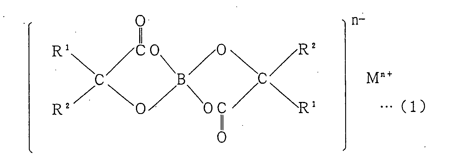
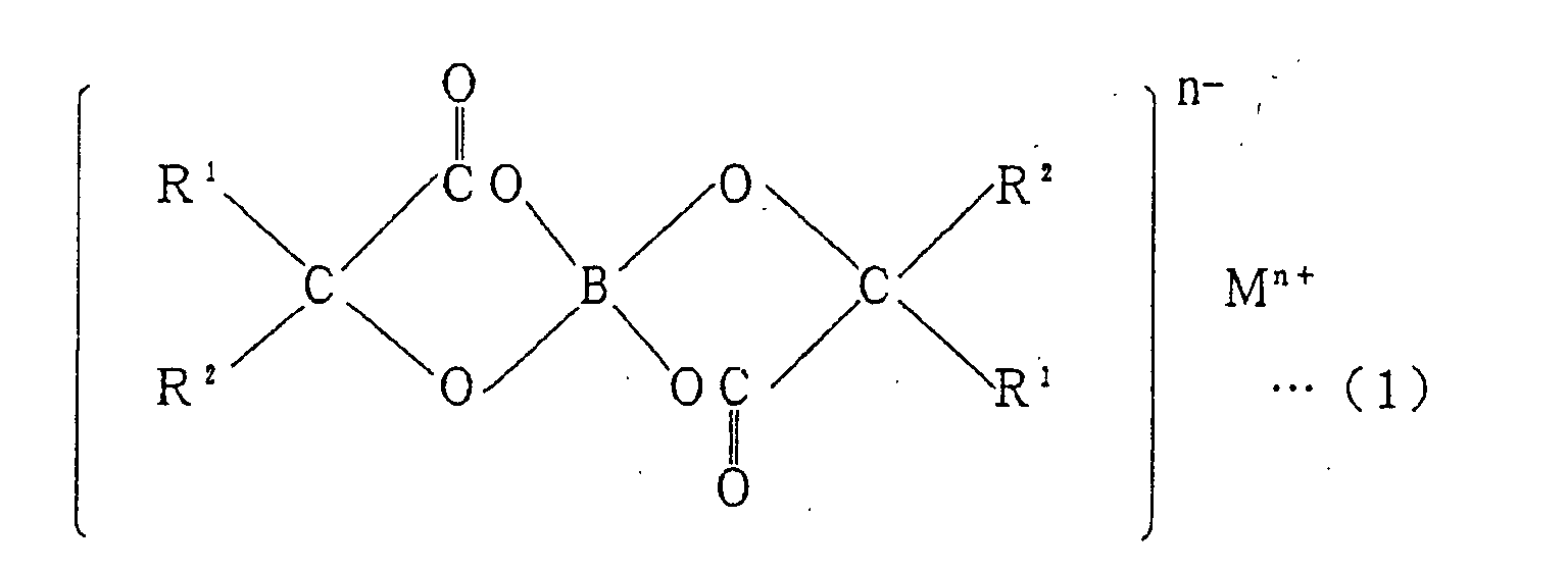
base polymer and a borate compound represented by the
following general formula (1):
wherein R
1 and R
2, which may be the same or different,
each represent a hydrogen atom, an alkyl group or an aryl
group; M is an alkaline metal or an alkaline earth metal;
and n is a positive number.
-
The inventors of the present invention conducted
intensive studies on an electrically conductive
composition to provide an electrically conductive foam
component which is free from blooming and has a stable
electrically conductive property. The inventors
further conducted studies, focusing on a borate compound
which is not generally used for ion conductive
applications. As a result, the inventors found that the
borate compound is slightly inferior in electrical
conductivity to a quaternary ammonium salt, but a product
produced by foaming a borate-containing composition has
a stable and practically acceptable electrically
conductive property (107 to 1010Ω·cm), and that the
borate compound is highly compatible with a base polymer.
Thus, the inventors found that an electrically
conductive foam compound produced by foaming an
electrically conductive composition comprising a base
polymer and a borate compound represented by the
aforesaid general formula (1) is free from blooming and
has a stable electrically conductive property, and
attained the present invention.
BRIEF DESCRIPTION OF THE DRAWINGS
-
- Fig. 1 is a perspective view illustrating a toner
supply roll as an example of an electrically conductive
foam component according to the present invention; and
- Fig. 2 is a sectional view for explaining a
production method for the toner supply roll.
-
DESCRIPTION OF THE PREFERRED EMBODIMENTS
-
The present invention will hereinafter be
described in detail by way of embodiments thereof.
-
An electrically conductive foam component
according to the present invention is produced by foaming
an electrically conductive composition comprising a base
polymer and a specific borate compound.
-
The base polymer is not particularly limited, but
examples thereof include urethane polymers,
acrylonitrile-butadiene rubbers (NBR), epichlorohydrin
rubbers (ECO), chloroprene rubbers (CR), acryl rubbers
(ACM), urethane rubbers, polar rubbers having
polyoxyalkylene units, and natural rubbers (NR), which
may be used either alone or in combination. Among these
polymers, liquid polymers such as urethane polymers and
liquid rubbers are preferred in consideration of an
expansion factor. The rubbers described above may be
in a solid form or in a liquid form.
-
The urethane polymers are not particularly
limited, but examples thereof include those derived from
ether based polyols such as polyether polyols and polymer
polyols, ester based polyols such as diethylene glycol
adipate, polycarbonate polyols and polycaprolactam
polyols, and olefin based polyols such as
polyoxyethylene polyols, polyoxypropylene polyols,
polyisoprene polyols, polybutadiene polyols and
hydrogenated isoprene polyols, which may be used either
alone or in combination. Among these urethane polymers,
the urethane polymers derived from the ether based
polyols (e.g., the polyether polyols and the polymer
polyols) and the ester based polyols (e.g., diethylene
glycol adipate) are preferred because they are highly
compatible with the aforesaid specific borate compound
and less water-absorptive.
-
The specific borate compound to be used in
combination with the base polymer is represented by the
following general formula (1):
wherein R
1 and R
2, which may be the same or different,
each represent a hydrogen atom, an alkyl group or an aryl
group; M is an alkaline metal or an alkaline earth metal;
and n is a positive number.
-
In the aforesaid general formula (1), the alkyl
group represented by R1 or R2 is not particularly limited,
but preferably an alkyl group having a carbon number of
1 to 18. Preferred examples of the alkyl group include
an ethyl group, a propyl group, a butyl group and a pentyl
group, among which the butyl group and the pentyl group
are particularly preferred.
-
In the aforesaid general formula (1), the aryl
group represented by R1 or R2 is not particularly limited,
but preferred examples thereof include a phenyl group,
a tolyl group, a xylyl group, a biphenylyl group, a
naphthyl group, an anthryl group and a phenanthryl group,
among which the phenyl group is particularly preferred.
-
In the aforesaid general formula (1), the alkaline
metal or the alkaline earth metal represented by M is
not particularly limited, but examples thereof include
lithium, potassium, calcium and sodium, among which
lithium and potassium are preferred.
-
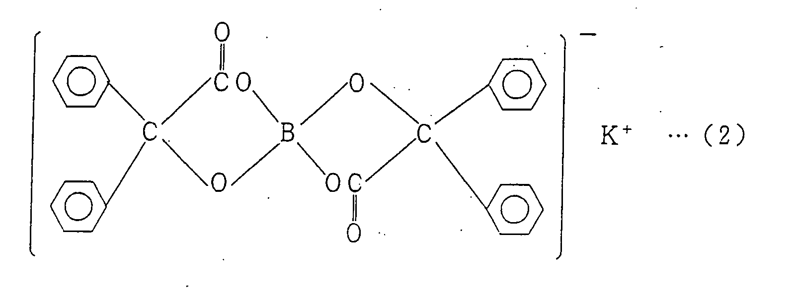
Among borate compounds represented by the
aforesaid general formula (1), a potassium borate
compound represented by the following formula (2) and
a lithium borate compound represented by the following
formula (3) are preferred in terms of electrical
conductivity and dispersion stability. The potassium
borate compound represented by the formula (2) is
particularly preferred.
-
The borate compound is preferably present in the
composition in a proportion of 0.001 to 20 parts by weight
(hereinafter referred to simply as "parts"), more
preferably 0.05 to 5 parts, based on 100 parts of the
base polymer. If the proportion of the borate compound
is smaller than 0.001 part, the resulting foam component
may have an insufficient electrically conductive
property. If the proportion of the borate compound is
greater than 20 parts, the resulting foam component tends
to have a higher hardness and suffer from blooming.
-
In addition to the base polymer and the specific
borate compound, additives such as one or more of a
cross-linking agent, a cross-linking accelerator, a
cross-linking assisting agent, an anti-aging agent, a
foaming agent, a foaming assisting agent, a catalyst and
a foam stabilizer may be blended in the electrically
conductive composition as required.
-
The cross-linking agent is not particularly
limited, but may properly be selected according to the
base polymer to be employed. Examples of cross-linking
agents include an isocyanate, a hydrosilyl cross-linking
agent, sulfur, a peroxide and a resin cross-linking agent,
which may be used either alone or in combination. Among
these cross-linking agents, the isocyanate and the
hydrosilyl cross-linking agent are preferred because
they provide higher cross-linking rates, higher
expansion factors with minute cells and smaller
permanent compression strains.
-
The isocyanate is not particularly limited, but
may be a polyisocyanate having two or more functional
groups. Specific examples of the polyisocyanate
include 4,4'-diphenylmethane diisocyanate (MDI),
isophorone diisocyanate (IPDI), 4,4'-dicyclohexylmethane
diisocyanate (hydrogenated MDI),
trimethylhexamethylene diisocyanate (TMHDI), tolylene
diisocyanate (TDI), carbodiimide-modified MDI,
polymethylene phenyl polyisocyanate (PAPI), o-toluidine
diisocyanate (TODI), naphthylene diisocyanate (NDI),
xylene diisocyanate (XDI), hexamethylene diisocyanate
(HMDI), p-phenylene diisocyanate (PDI), lysine
diisocyanate methyl ester (LDI) and dimethyl
diisocyanate (DDI), which may be used either alone or
in combination. Among these isocyanates, MDI and TDI
are preferred. These isocyanates may be used in the form
of an intermediate product, for example, in an adduct
form, a prepolymer form or a block form.
-
The isocyanate is preferably present in the
composition in a proportion of 5 to 40 parts,
particularly preferably 10 to 25 parts, based on 100
parts of the base polymer.
-
The hydrosilyl cross-linking agent is not
particularly limited, but examples thereof include those
having a hydrosilyl group in a molecule thereof. The
hydrosilyl group has a silicon atom and a hydrogen
atom(s) bonded to at least one of four bonding sites of
the silicon atom.
-
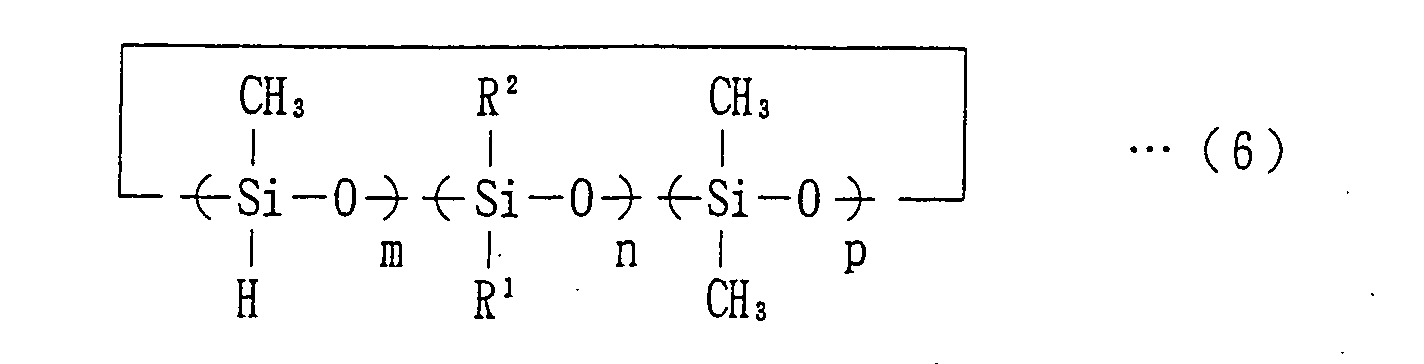
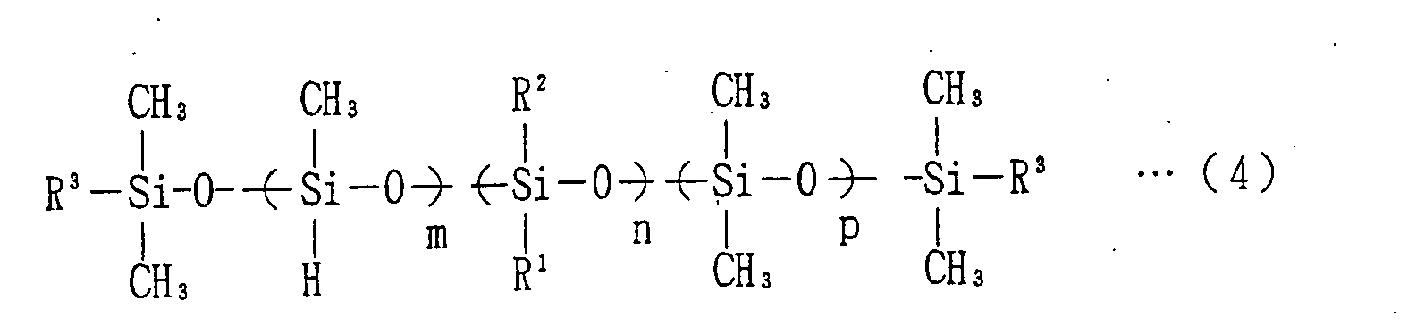
Among the aforesaid hydrosilyl cross-linking
agents, hydrosilyl cross-linking agents represented by
the following general formulae (4) to (6) are preferred
because they are highly compatible with the base polymer
and highly resistant to permanent compression strain.
In the following general formulae, repeating units
identified by numerals m, n, p may be polymerized by any
polymerization method, e.g., by random polymerization
or block polymerization.
wherein group R
1 is a hydrocarbon group having a carbon
number of 2 to 20; group R
2 is a hydrocarbon group having
a carbon number of 1 to 20; groups R
3, which may be the
same or different, each represent a hydrogen atom or a
methyl group; m is a positive number of not smaller than
1; n is a positive number of not smaller than 1; p is
0 or a positive number; and m, n and p satisfy 2 ≦ m+n+p
≦ 200.
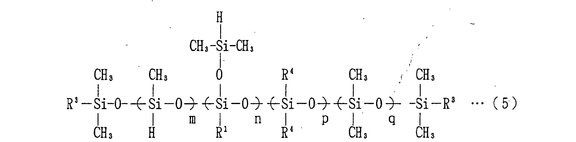
wherein group R
1 is a hydrocarbon group having a carbon
number of 2 to 20; groups R
3, which may be the same or
different, each represent a hydrogen atom or a methyl
group; groups R
4, which may be the same or different, each
represent a hydrocarbon group having a carbon number of
1 to 20; m is 0 or a positive number; n is a positive
number of not smaller than 1; p is 0 or a positive number;
q is 0 or a positive number; and m, n, p and q satisfy
1 ≦ m+n+p+q ≦ 200.
wherein group R
1 is a hydrocarbon group having a carbon
number of 2 to 20; group R
2 is a hydrocarbon group having
a carbon number of 1 to 20; m is a positive number of
not smaller than 2; n is a positive number of not smaller
than 1; p is 0 or a positive number; and m, n and p satisfy
3 ≦ m+n+p ≦ 500.
-
The hydrosilyl cross-linking agents represented
by the aforesaid general formulae (4) to (6) are prepared
by the following
methods 1 ○ to 4 ○, among which the method
3 ○ is particularly preferred for easier preparation of
the hydrosilyl cross-linking agents.
- 1 ○ A hydrocarbon compound having a chlorosilyl group
(SiCl) in its molecule is treated with a reducing agent
(e.g., LiAlH4, NaBH4) for reduction of the chlorosilyl
group into a hydrosilyl group.
- 2 ○ A hydrocarbon compound having a functional group
is reacted with a compound having a hydrosilyl group and
a functional group reactive with the functional group
of the hydrocarbon compound.
- 3 ○ A hydrocarbon compound having an alkenyl group is
reacted with a polyhydrosilane compound so that a
hydrosilyl group remains in the molecular structure of
the resulting reaction product.
- 4 ○ A cyclic siloxane having a hydrosilyl group is
reacted with a cyclic siloxane having a hydrocarbon
group.
-
-
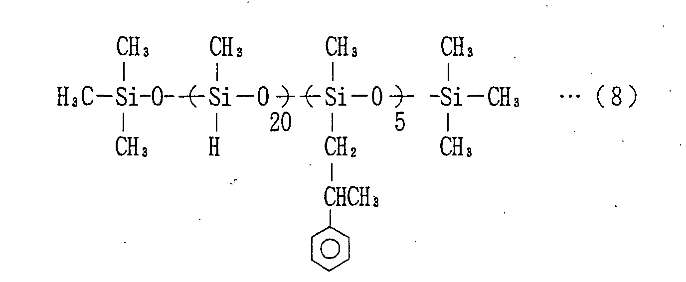
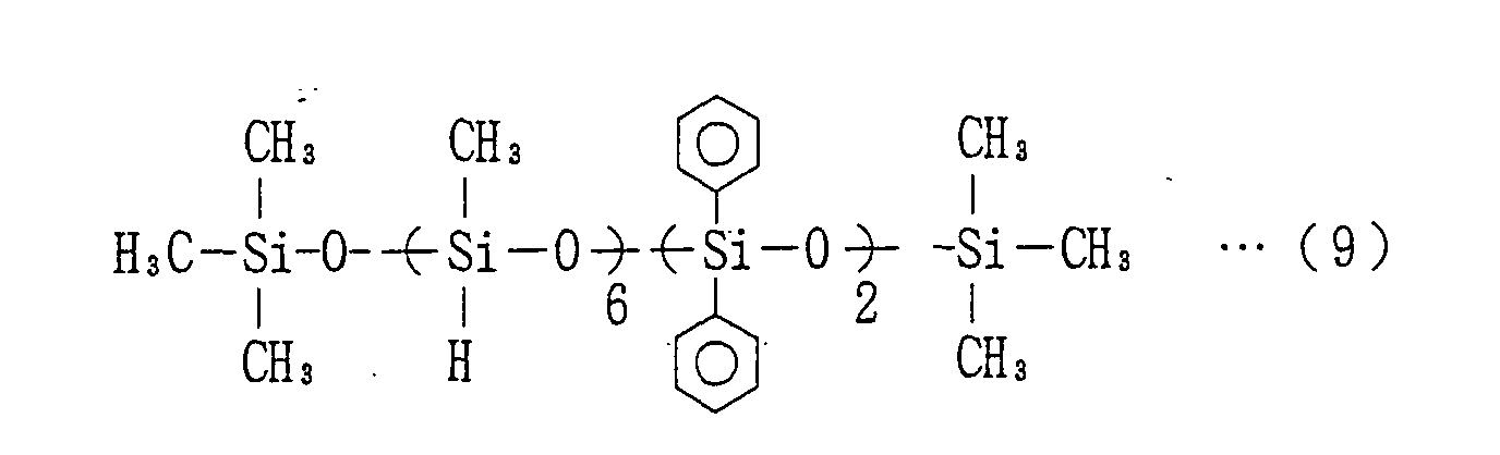
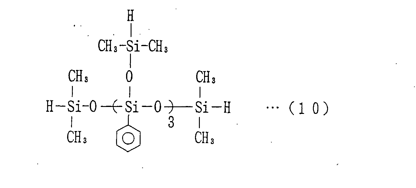
Among the hydrosilyl cross-linking agents thus
prepared, those having the following structural formulae
(7) to (11) are particularly preferred. Repeating units
in each of the hydrosilyl cross-linking agents may be
polymerized by any polymerization method, e.g., by
random polymerization or block polymerization.
-
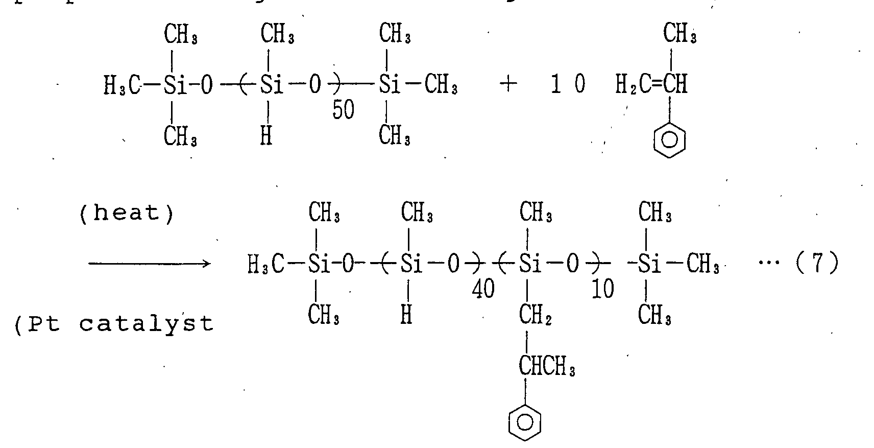
For example, the hydrosilyl cross-linking agent
represented by the above structural formula (7) is
prepared through the following reaction:
-
Preparation of the hydrosilyl cross-linking
agents represented by the above structural formulae (8)
to (11) is achieved in substantially the same manner as
the preparation of the hydrosilyl cross-linking agent
represented by the aforesaid structural formula (7).
-
The hydrosilyl cross-linking agent is preferably
present in the composition in a proportion of 1 to 35
parts, particularly preferably 2 to 18 parts, based on
100 parts of the base polymer.
-
Examples of the foaming agent include water,
chemical foaming agents such as N,N'-dinitrosopentamethylenetetramine
(DPT), 2,2'-azoisobutyronitrile
(AIBN), 4,4'-oxybis(benzene
sulfonyl hydrazide) (OBSH), azodicarbonamide (ADCA),
p-toluenesulfonyl hydrazide (TSH) and sodium
bicarbonate (baking soda) , foaming agents which generate
water, nitrogen, hydrogen or carbon dioxide in a reaction,
foaming agents which disperse and dissolve gas in the
composition for foaming of the composition, and foaming
agents which utilize a volume change from a hypercritical
or hypocritical phase into a gaseous phase by pressure
and temperature control.
-
The foaming agent is preferably present in the
composition in a proportion of 1 to 15 parts,
particularly preferably 3 to 7 parts, based on 100 parts
of the base polymer.
-
Examples of the catalyst include tertiary amine
catalysts, organic metal compounds, and hydrosilylation
catalysts.
-
Examples of the tertiary amine catalysts include:
monoamines such as triethylamine (TEA), N,N-dimethylcyclohexylamine
(DMEDA); diamines such as
N,N,N',N'-tetramethylethylenediamine (TMEDA);
triamines such as N,N',N",N"-pentamethyldiethylenetriamine
(PMDETA); cyclic amines
such as triethylenediamine (TEDA); alcoholamines such
as dimethylaminoethanol (DMEA); etheramines such as
bis(2-dimethylaminoethyl) ether (BDMEE). These amine
catalysts may be used either alone or in combination.
-
Examples of the organic metal compound include
stannous octoate, dibutyltin diacetate, dibutyltin
dilaurate and dibutyltin thiocarboxylate, which may be
used either alone or in combination.
-
Examples of the foam stabilizer include silicone
based foam stabilizers (polyoxyalkylenedimethylpolysiloxane
copolymers) and non-silicone based
foam stabilizers (acrylic copolymers).
-
Next; a toner supply roll as shown in Fig. 1 will
be described as a specific example of the inventive
electrically conductive foam component. The toner
supply roll is of a single layer structure, which
comprises a shaft 1 and an electrically conductive foam
layer 2 of the urethane foam or the elastomer foam
provided around the shaft 1. In the present invention,
the electrically conductive foam layer 2 is formed by
foaming the electrically conductive composition
containing the specific borate compound.
-
The shaft 1 is not particularly limited, but may
be a solid metal shaft or a hollow cylindrical metal shaft,
for example. Exemplary materials for the shaft 1
include stainless steel, aluminum and plated iron.
-
As described above, the electrically conductive
foam layer 2 is formed by foaming the electrically
conductive composition containing the specific borate
compound.
-
The toner supply roll shown in Fig. 1 is produced,
for example, in the following manner. As shown in Fig.
2, a mold is prepared which includes a cylindrical mold
portion 21 having a length nearly equal to the axial
length of the electrically conductive layer 2 of the
toner supply roll and caps 22, 23 for closing opposite
ends of the cylindrical mold portion 21. The shaft 1
is positioned in the cylindrical mold portion 21, and
the opposite ends of the cylindrical mold portion 21 are
closed with the caps 22, 23 with opposite ends of the
shaft 1 respectively held by the caps 22, 23, whereby
a mold cavity 24 is defined in the cylinder mold portion
21 to provide a final roll shape (outer diameter) of the
intended toner supply roll. As the material for the
electrically conductive foam layer 2, the electrically
conductive composition containing the borate compound
is injected into the mold cavity 24, and heated in an
oven at a predetermined temperature (about 60 ° C) for a
predetermined period (about 30 minutes) for foaming and
cross-linking thereof. Then, the resulting product is
unmolded. Thus, the toner supply roll of the single
layer structure is provided, which has the electrically
conductive foam layer 2 around the shaft 1 as shown in
Fig. 1.
-
The expansion factor of the electrically
conductive foam layer 2 is preferably 2 to 12,
particularly preferably 3 to 10. If the expansion
factor is smaller than 2, it may be impossible to impart
the electrically conductive foam layer with a desired
flexibility and a desired cell configuration. If the
expansion factor is greater than 12, the electrically
conductive foam layer tends to have an insufficient
strength and thereby may be broken during unmolding or
chipped during use.
-
The electrically conductive foam layer 2
typically has a thickness of 2 to 8 mm, preferably 3 to
6 mm.
-
The structure of the toner supply roll according
to the present invention is not limited to the single
layer structure shown in Fig. 1, but the toner supply
roll may be of a multi-layer structure having two or more
layers.
-
The electrically conductive foam component
according to the present invention is not limited to use
in a toner supplying member, e.g., the toner supply roll
shown in Fig. 1. The electrically conductive foam
component is applicable to other electrophotographic
apparatus members, e.g., a transferring member such as
a transfer roll or a transfer belt, a developing member
such as a developing roll, a charging member such as a
charging roll, a sheet feeding and transporting member
such as a sheet feed roll, and a cleaning member such
as a cleaning roll or a cleaning blade.
-
Next, an explanation will be given to examples and
comparative examples.
-
Prior to the explanation of the examples and the
comparative examples, preparation of the following
electrically conductive compositions will be described.
Electrically conductive composition (A)
-
An electrically conductive composition (A)
(polyurethane material) was prepared, which contained
90 parts of a polyether polyol (FA718 available from
Sanyo Kasei Co.), 10 parts of a polymer polyol (POP31-28
available from Mitsui Chemicals, Inc.), 0.5 parts of a
tertiary amine catalyst (KAORIZER No.31 available from
Kao Corporation), 0.05 parts of a tertiary amine catalyst
(TOYOCAT HX-35 available from Toso Co., Ltd.), 2 parts
of a foaming agent (water), 2 parts of a silicone based
foam stabilizer (L-5309 available from Nippon Uniker Co.,
Ltd. ), 8.8 parts of a crude MDI (SUMIDUR 44V20 available
from Sumitomo Bayer Urethane Co, Ltd.), 20.5 parts of
tolylene diisocianate (TDI-80 available from Mitsui
Chemicals, Inc.), and 1 part of a potassium borate
compound represented by the formula (2) (LR147 available
from Nippon Carlit Co., Ltd.).
Electrically conductive composition (B)
-
An electrically conductive composition (B)
(polyurethane material) was prepared in substantially
the same manner as the electrically conductive
composition (A), except that 1 part of a lithium borate
compound represented by the formula (3) (PEL20BBL
available from Nippon Carlit Co., Ltd.) was employed
instead of 1 part of the potassium borate compound (LR147
available from Nippon Carlit Co., Ltd.).
Electrically conductive composition (C)
-
An electrically conductive composition (C)
(polyurethane material) was prepared, which contained
100 parts of diethylene glycol adipate (ODX2376
available from Dainippon Ink and Chemicals, Inc.), 0.5
parts of a tertiary amine catalyst (KAORIZER No.31
available from Kao Corportation), 0.05 parts of a
tertiary amine catalyst (TOYOCAT HX-35 available from
Toso Co., Ltd.), 2 parts of a foaming agent (water), 2
parts of a silicone based foam stabilizer (L-5309
available from Nippon Uniker Co., Ltd.), 8.8 parts of
a crude MDI (SUMIDUR 44V20 available from Sumitomo Bayer
Urethane Co, Ltd.), 20.5 parts of tolylene diisocianate
(TDI-80 available from Mitsui Chemicals, Inc.), and 1
part of a potassium borate compound (LR147 available from
Nippon Carlit Co., Ltd.).
Electrically conductive composition (D)
-
An electrically conductive composition (D)
(polyurethane material) was prepared in substantially
the same manner as the electrically conductive
composition (A), except that the proportion of the
potassium borate compound (LR147 available from Nippon
Carlit Co., Ltd.) was increased to 20 parts.
Electrically conductive composition (E)
-
An electrically conductive composition (E)
(rubber composition) was prepared, which contained 80
parts of NBR containing nitrile at a medium- to
high-ratio (JSRN230S available from JSR Co., Ltd.), 20
parts of a liquid NBR (NIPOLE 1312 available from Nippon
Zeon Co., Ltd.), 1.5 parts of sulfur (cross-linking
agent), 5 parts of ZnO (zinc white No.1, cross-linking
assisting agent), 1 part of stearic acid (cross-linking
assisting agent), 50 parts of calcium carbonate (filler,
WHITEN available from Shiraishi Calcium Co., Ltd.), 0.6
parts of a cross-linking accelerator (NOCCELER TS
available from Ouchi Shinko Chemical Industry Co., Ltd.),
1.5 parts of an anti-aging agent (OZONON 3C available
from Seika Chemical Co., Ltd.), 1 part of a potassium
borate compound (LR147 available from Nippon Carlit Co.,
Ltd.), 6 parts of N,N'-dinitrosopentamethylenetetramine
(DPT, foaming agent), and 6 parts of a foaming assisting
agent (CELLTON N available from Sankyo Kasei K.K.).
Electrically conductive composition (F)
-
An electrically conductive composition (F)
(rubber composition) was prepared, which contained 100
parts of an epichlorohydrin rubber (EPICHLOMER CG
available from Daiso Co., Ltd.), 1.5 parts of sulfur
(cross-linking agent), 5 parts of ZnO (zinc white No.1,
cross-linking assisting agent), 1 part of stearic acid
(cross-linking assisting agent), 50 parts of calcium
carbonate (filler, WHITEN available from Shiraishi
Calcium Co., Ltd.), 1 part of a cross-linking accelerator
(SANCELER CZ available from Sanshin Chemical Industry
Co., Ltd.), 1 part of a cross-linking accelerator
(NOCCELER BZ available from Ouchi Shinko Chemical
Industry Co., Ltd.), 1 part of a potassium borate
compound (LR147 available from Nippon Carlit Co., Ltd.),
6 parts of N,N'-dinitrosopentamethylenetetramine (DPT,
foaming agent), and 6 parts of a foaming assisting agent
(CELLTON N available from Sankyo Kasei K.K.).
Electrically conductive composition (G)
-
An electrically conductive composition (G)
(rubber composition) was prepared, which contained 100
parts of a chloroprene rubber (NEOPRENE WRT available
from Showa DDE Manufacturing Co., Ltd.), 1.5 parts of
a thiourea based cross-linking agent (SANCELER 22C
available from Sanshin Chemical Industry Co., Ltd.), 5
parts of ZnO (zinc white No.1, cross-linking assisting
agent), 1 part of stearic acid (cross-linking assisting
agent), 30 parts of calcium carbonate (filler, WHITEN
available from Shiraishi Calcium Co., Ltd.), 1 part of
a potassium borate compound (LR147 available from Nippon
Carlit Co., Ltd.), 6 parts of N,N'-dinitrosopentamethylenetetramine
(DPT, foaming agent),
and 6 parts of a foaming assisting agent (CELLTON N
available from Sankyo Kasei K.K.).
Electrically conductive composition (H)
-
An electrically conductive composition (H)
(rubber composition) was prepared, which contained 100
parts of an acryl rubber (DENKA ER3400 available from
Denki Kagaku Kogyo K.K.), 1 part of an amine based
cross-linking agent (Diak No.1 available from Dupont Dow
Elastomer Co.), 5 parts of ZnO (zinc white No.1,
cross-linking assisting agent), 2 parts of stearic acid
(cross-linking assisting agent), 30 parts of calcium
carbonate (filler, WHITEN available from Shiraishi
Calcium Co., Ltd.), 2 parts of a cross-linking
accelerator (SOXINOL DT available from Sumitomo Chemical
Co., Ltd.), 1 part of a potassium borate compound (LR147
available from Nippon Carlit Co., Ltd.), 6 parts of
N,N'-dinitrosopentamethylenetetramine (DPT, foaming
agent), and 6 parts of a foaming assisting agent (CELLTON
N available from Sankyo Kasei K.K.).
Electrically conductive composition (I)
-
An electrically conductive composition (I)
(rubber composition) was prepared, which contained 80
parts of a natural rubber (RSS #1), 20 parts of a
depolymerized liquid natural rubber (DPR available from
ELEMENTIS Co., Ltd.), 3.5 parts of sulfur (cross-linking
agent), 6 parts of ZnO (zinc white No.1, cross-linking
assisting agent), 50 parts of calcium carbonate (filler,
WHITEN available from Shiraishi Calcium Co., Ltd.), 1
part of a cross-linking accelerator (NOCCELER DM
available from Ouchi Shinko Chemical Industry Co., Ltd.),
1 part of an anti-aging agent (NOCRAC 6C available from
Ouchi Shinko Chemical Industry Co., Ltd.), 1 part of a
potassium borate compound (LR147 available from Nippon
Carlit Co., Ltd.), 6 parts of N,N'-dinitrosopentamethylenetetramine
(DPT, foaming agent,
CELLMIC A available from Sankyo Kasei K.K.), and 6 parts
of a foaming assisting agent (CELLTON N available from
Sankyo Kasei K.K.).
Electrically conductive composition (J)
-
An electrically conductive composition (J)
(rubber composition) was prepared, which contained 100
parts of a urethane rubber (UN278 available from Sakai
Chemical Industry Co., Ltd.), 1 part of sulfur
(cross-linking agent), 5 parts of ZnO (zinc white No.1,
cross-linking assisting agent), 1 part of a cross-linking
accelerator (Thanecure available from TSE
Industries Co.), 2 parts of a cross-linking accelerator
(SOXINOL MP available from Sumitomo Chemical Co., Ltd.),
1 part of a cross-linking accelerator (NOCCELER DM
available from Ouchi Shinko Chemical Industry Co. , Ltd.),
1 part of a potassium borate compound (LR147 available
from Nippon Carlit Co., Ltd.), 6 parts of N,N'-dinitrosopentamethylenetetramine
(DPT, foaming agent,
CELLMIC A available from Sankyo Kasei K.K.), and 6 parts
of a foaming assisting agent (CELLTON N available from
Sankyo Kasei K.K.).
Electrically conductive composition (K)
-
An electrically conductive composition (K)
(liquid rubber composition) was prepared, which
contained 100 parts of a vinyl terminated liquid
polyether polymer (SILYL ACX009A available from
Kanegafuchi Kagaku Kogyo K.K.), 0.003 parts of a
hydrosilylation catalyst, 6.2 parts of a hydrosilyl
cross-linking agent represented by the aforesaid formula
(8), 1 part of a potassium borate compound (LR147
available from Nippon Carlit Co. , Ltd.), and 6 parts of
2,2'-azoisobutyronitrile (AIBN) (foaming agent).
Electrically conductive composition (L)
-
An electrically conductive composition (L)
(liquid rubber composition) was prepared, which
contained 100 parts of a polyether polyol (polypropylene
glycol terminated ethylene oxide having an OH equivalent
of 1000, GL3000 available from Sanyo Kasei Co.), 0.0001
part of a chlorinated platinumate (catalyst), 3 parts
of an activated hydrogen containing compound (isopropyl
alcohol), 25.7 parts of a hydrosilyl cross-linking agent
represented by the following formula (12), and 1 part
of a potassium borate compound (LR147 available from
Nippon Carlit Co., Ltd.).
Electrically conductive composition (a)
-
An electrically conductive composition (a)
(polyurethane material) was prepared, which contained
100 parts of a polyoxypropylene glycol (MITECH TN2192
available from Mitsubishi Chemical Corporation), 15
parts of a urethane prepolymer prepared by
prepolymerization of PPG with MDI (GP512A available from
Mitsubishi Chemical Corporation), and 0.5 parts of a
potassium borate compound (LR147 available from Nippon
Carlit Co., Ltd.).
Electrically conductive composition (b)
-
An electrically conductive composition (b)
(polyurethane material) was prepared in substantially
the same manner as the electrically conductive
composition (A), except that the potassium borate
compound (LR147 available from Nippon Carlit Co., Ltd. )
was not blended.
Electrically conductive composition (c)
-
An electrically conductive composition (c)
(polyurethane material) was prepared in substantially
the same manner as the electrically conductive
composition (A), except that 3 parts of electrically
conductive carbon black (KETJEN BLACK EC available from
Ketjen Black International Co.) was employed instead of
1 part of the potassium borate compound (LR147 available
from Nippon Carlit Co., Ltd.).
Electrically conductive composition (d)
-
An electrically conductive composition (d)
(polyurethane material) was prepared in substantially
the same manner as the electrically conductive
composition (A), except that a lithium perchlorate
compound (PEL20A available from Nippon Carlit Co., Ltd.)
was employed instead of the potassium borate compound
(LR147 available from Nippon Carlit Co., Ltd.).
Electrically conductive composition (e)
-
An electrically conductive composition (e)
(polyurethane material) was prepared in substantially
the same manner as the electrically conductive
composition (A), except that a quaternary ammonium salt
(TBAHS available from Lion Corporation) was employed
instead of the potassium borate compound (LR147
available from Nippon Carlit Co., Ltd.).
Electrically conductive composition (f)
-
An electrically conductive composition (f)
(polyurethane material) was prepared, which contained
100 parts of diethylene glycol adipate (.ODX2376
available from Dainippon Ink and Chemicals, Inc.), 0.5
parts of a tertiary amine catalyst (KAORIZER No.31
available from Kao Corporation), 0.05 parts of a tertiary
amine catalyst (TOYOCAT HX-35 available from Toso Co.,
Ltd.), 2 parts of a foaming agent (water), 2 parts of
a silicone based foam stabilizer (L-5309 available from
Nippon Uniker Co., Ltd.), 8.8 parts of a crude MDI
(SUMIDUR 44V20 available from Sumitomo Bayer Urethane
Co, Ltd.), 20.5 parts of tolylene diisocyanate (TDI-80
available from Mitsui Chemicals, Inc.), and 1 part
of a quaternary ammonium salt (TBAHS available from Lion
Corporation).
Electrically conductive composition (g)
-
An electrically conductive composition (g)
(rubber composition) was prepared, which contained 80
parts of NBR containing nitrile at a medium- to
high-ratio (JSRN230S available from JSR Co., Ltd.), 20
parts of a liquid NBR (NIPOLE 1312 available from Nippon
Zeon Co., Ltd.), 1.5 parts of sulfur (cross-linking
agent), 5 parts of ZnO (zinc white No.1, cross-linking
assisting agent), 1 part of stearic acid (cross-linking
assisting agent), 50 parts of calcium carbonate (filler,
WHITEN available from Shiraishi Calcium Co., Ltd.), 0.6
parts of a cross-linking accelerator (NOCCELER TS
available from Ouchi Shinko Chemical Industry Co., Ltd.),
1.5 parts of an anti-aging agent (OZONON 3C available
from Seika Chemical Co., Ltd.), 1 part of a quaternary
ammonium salt (TBAHS available from Lion Corporation),
6 parts of N,N'-dinitrosopentamethylenetetramine (DPT,
foaming agent), and 6 parts of a foaming assisting agent
(CELLTON N available from Sankyo Kasei K.K.).
Electrically conductive composition (h)
-
An electrically conductive composition (h)
(rubber composition) was prepared, which contained 100
parts of an epichlorohydrin rubber (EPICHLOMER CG
available from Daiso Co., Ltd.), 1.5 parts of sulfur
(cross-linking agent), 5 parts of ZnO (zinc white No.1,
cross-linking assisting agent), 1 part of stearic acid
(cross-linking assisting agent), 50 parts of calcium
carbonate (filler, WHITEN available from Shiraishi
Calcium Co., Ltd.), 1 part of a cross-linking accelerator
(SANCELER CZ available from Sanshin Chemical Industry
Co., Ltd.), 1 part of a cross-linking accelerator
(NOCCELER BZ available from Ouchi Shinko Chemical
Industry Co., Ltd.), 1 part of a quaternary ammonium salt
(TBAHS available from Lion Corporation), 6 parts of
N,N'-dinitrosopentamethylenetetramine (DPT, foaming
agent), and 6 parts of a foaming assisting agent (CELLTON
N available from Sankyo Kasei K.K.).
Electrically conductive composition (i)
-
An electrically conductive composition (i)
(rubber composition) was prepared, which contained 80
parts of a natural rubber (RSS #1), 20 parts of a
depolymerized liquid natural rubber (DPR available from
ELEMENTIS Co., Ltd.), 3.5 parts of sulfur (cross-linking
agent), 6 parts of ZnO (zinc white No.1, cross-linking
assisting agent), 50 parts of calcium carbonate (filler,
WHITEN available from Shiraishi Calcium Co., Ltd.), 1
part of a cross-linking accelerator (NOCCELER DM
available from Ouchi Shinko Chemical Industry Co., Ltd.),
1 part of an anti-aging agent (NOCRAC 6C available from
Ouchi Shinko Chemical Industry Co. , Ltd.), 1 part of a
quaternary ammonium salt (TBAHS available from Lion
Corporation), 6 parts of N,N'-dinitrosopentamethylenetetramine
(DPT, foaming agent,
CELLMIC A available from Sankyo Kasei K.K.), and 6 parts
of a foaming assisting agent (CELLTON N available from
Sankyo Kasei K.K.).
Electrically conductive composition (j)
-
An electrically conductive composition (j)
(rubber composition) was prepared, which contained 100
parts of a urethane rubber (UN278 available from Sakai
Chemical Industry Co., Ltd.), 1 part of sulfur
(cross-linking agent), 5 parts of ZnO (zinc white No.1,
cross-linking assisting agent), 1 part of a cross-linking
accelerator (Thanecure available from TSE
Industries Co.), 2 parts of a cross-linking accelerator
(SOXINOL MP available from Sumitomo Chemical Co., Ltd.),
1 part of a cross-linking accelerator (NOCCELER DM
available from Ouchi Shinko Chemical Industry Co. , Ltd.),
1 part of a quaternary ammonium salt (TBAHS available
from Lion Corporation), 6 parts of N,N'-dinitrosopentamethylenetetramine
(DPT, foaming agent,
CELLMIC A available from Sankyo Kasei K.K.), and 6 parts
of a foaming assisting agent (CELLTON N available from
Sankyo Kasei K.K.).
Electrically conductive composition (k)
-
An electrically conductive composition (k)
(liquid rubber composition) was prepared, which
contained 100 parts of a vinyl terminated liquid
polyether polymer (SILYL ACX009A available from
Kanegafuchi Kagaku Kogyo K.K.), 0.003 parts of
chlorinated platinumate (hydrosilylation catalyst), 6.2
parts of a hydrosilyl cross-linking agent represented
by the aforesaid formula (8), 1 part of a quaternary
ammonium salt (TBAHS available from Lion Corporation),
and 6 parts of 2,2 '-azoisobutyronitrile (AIBN) (foaming
agent).
Example 1
-
A mold for molding a toner supply roll was prepared.
After a metal shaft (composed of SUS304 and having a
diameter of 5 mm) was set in a cylindrical mold portion
of the mold, the electrically conductive composition (A)
(polyurethane material) was injected into a mold cavity
of the mold, foamed and cross-linked. Then, the
resulting product was unmolded. Thus, a toner supply
roll was produced, which had an electrically conductive
urethane foam layer (having a thickness of 4 mm) formed
around the shaft.
Examples 2 to 12
-
Toner supply rolls were produced in substantially
the same manner as in Example 1, except that the
electrically conductive compositions shown in Tables 1
and 2 were employed instead of the electrically
conductive composition (A).
Comparative Example 1
-
A toner supply roll was produced according to an
embodiment described in Japanese Unexamined Patent
Publication No. HEI10(1998)-48912. More specifically,
a mold for molding a toner supply roll was prepared.
After a metal shaft (composed of SUS304 and having a
diameter of 5 mm) was set in a cylindrical mold portion
of the mold, the electrically conductive composition (a)
(polyurethane material) was injected into a mold cavity
of the mold, and heated and cured at 100 ° C for 30 minutes.
Then, the resulting product was unmolded. Thus, a toner
supply roll was produced, which had a cured urethane
layer (having a thickness of 4 mm) formed around the shaft.
It is noted that the cured urethane layer is not in a
foamed form and, hence, differs from the electrically
conductive urethane foam layer according to Example 1.
Comparative Examples 2 to 11
-
Toner supply rolls were produced in substantially
the same manner as in Example 1, except that the
electrically conductive compositions shown in Tables 3
and 4 were employed instead of the electrically
conductive composition (A).
-
The toner supply rolls of the examples and the
comparative examples thus produced were evaluated for
their properties in the following manners. The results
of the evaluation are shown in Tables 1 to 4.
Expansion factor
-
The pre-foaming specific gravity and post-foaming
specific gravity of each of the electrically
conductive compositions were measured in conformity with
Japanese Industrial Standard (JIS) K7222, and the ratio
of the pre-foaming specific gravity to the post-foaming
specific gravity was determined as the expansion factor.
Stability of material
-
The materials (electrically conductive
compositions) were each visually inspected for
separation (or sedimentation) after they were stored at
a room temperature for one month. For the evaluation
of the stabilities of the materials in Tables 1 to 4,
a symbol ○ indicates that no separation (nor
sedimentation) occurred, and a symbol × indicates that
separation (or sedimentation) occurred.
Electrical resistance (median)
-
The toner supply rolls were each placed on a SUS304
plate having a thickness of 5 mm, and then an electrical
resistance (median) between the shaft and the plate was
measured under conditions of 20°C and 50%RH while
opposite ends of the roll were each pressed against the
plate with a force of 500 g.
Variation in electrical resistance
-
The electrical resistance of each of the toner
supply rolls was measured at ten different points in
conformity with the method specified in SRIS 2304. At
this time, a voltage applied to the roll was 500 V. For
the evaluation of the variation in electrical resistance
in Tables 1 to 4, a difference between maximum and minimum
levels out of the measurements of the electrical
resistance at the ten points is shown on a logarithmic
basis.
Blooming resistance
-
The toner supply rolls were each incorporated in
a printer (MICROLINE 400 available from Oki Electric
Industry Co., Ltd.), and allowed to stand under
conditions of 25 ° C and 53%RH for one month. Then, the
toner supply roll was visually inspected for blooming.
For the evaluation of the blooming resistance in Tables
1 to 4, a symbol ○ indicates that the blooming did not
occur, and a symbol × indicates that the blooming
occurred.
Cross-linking rate
-
For the evaluation of the cross-linking rate in
Tables 1 to 4, a symbol ○ indicates that the degree of
the cross-linking exceeded 90% within 5 minutes when the
electrically conductive composition was cross-linked at
a temperature of not higher than 100 ° C, and a symbol Δ
indicates that the degree of the cross-linking exceeded
90% within 15 minutes when the electrically conductive
composition was cross-linked at a temperature of not
higher than 150° C. A symbol × indicates that the
electrically conductive composition falls into neither
of the aforesaid categories.
Toner supply sustainability
-
The toner supply rolls were each incorporated in
a printer (MICROLINE 400 available from Oki Electric
Industry Co., Ltd. ) and, after 5,000 printed sheets were
outputted, the condition of the toner supply roll was
inspected. For the evaluation of the toner supply
sustainability in Tables 1 to 4, a symbol ○ indicates
that the roll was free from toner clogging and hence
exerted no influence on outputted images, and a symbol
× indicates that the roll suffered from toner clogging
with influenced outputted images.
| | Example |
| | 1 | 2 | 3 | 4 | 5 | 6 |
| Electrically conductive composition | A | B | C | D | E | F |
| Expansion factor | 10.5 | 11.2 | 9.5 | 4.6 | 2.5 | 4.1 |
| Stability of material | ○ | ○ | ○ | ○ | ○ | ○ |
| Median electrical resistance (Ω) | 3 × 10⁸ | 2 × 10⁸ | 2 × 10⁹ | 1 × 10⁷ | 7 × 10⁸ | 8 × 10⁷ |
| Variation in electrical resistance (on logarithmic basis) | 0.3 | 0.3 | 0.3 | 0.3 | 0.3 | 0.3 |
| Blooming resistance | ○ | ○ | ○ | ○ | ○ | ○ |
| Cross-linking rate | ○ | ○ | ○ | ○ | Δ | Δ |
| Toner supply sustainability | ○ | ○ | ○ | ○ | ○ | ○ |
| | Example |
| | 7 | 8 | 9 | 10 | 11 | 12 |
| Electrically conductive composition | G | H | I | J | K | L |
| Expansion factor | 2.8 | 3.9 | 3.6 | 4.2 | 6.2 | 9.7 |
| Stability of material | ○ | ○ | ○ | ○ | ○ | ○ |
| Median electrical resistance (Ω) | 4 × 10⁹ | 1.5 × 10⁹ | 4 × 10⁹ | 3 × 10⁸ | 5 × 10⁸ | 9 × 10⁷ |
| Variation in electrical resistance (on logarithmic basis) | 0.3 | 0.3 | 0.3 | 0.3 | 0.3 | 0.3 |
| Blooming resistance | ○ | ○ | ○ | ○ | ○ | ○ |
| Cross-linking rate | Δ | Δ | Δ | Δ | ○ | ○ |
| Toner supply sustainability | ○ | ○ | ○ | ○ | ○ | ○ |
| | Comparative Example |
| | 1 | 2 | 3 | 4 | 5 | 6 |
| Electrically conductive composition | a | b | c | d | e | f |
| Expansion factor | - | 12.1 | 6.8 | 10.9 | 10.4 | 8.8 |
| Stability of material | ○ | ○ | × | × | × | × |
| Median electrical resistance (Ω) | 2 × 10⁸ | 3 × 10¹¹ | 5 × 10⁸ | 2 X 10⁸ | 8 × 10⁸ | 2 × 10⁹ |
| Variation in electrical resistance (on logarithmic basis) | 0.2 | 0.2 | 3.2 | 0.3 | 0.3 | 0.3 |
| Blooming resistance | ○ | ○ | ○ | × | × | × |
| Cross-linking rate | ○ | ○ | ○ | ○ | ○ | ○ |
| Toner supply sustainability | × | × | × | × | × | × |
| | Comparative Example |
| | 7 | 8 | 9 | 10 | 11 |
| Electrically conductive composition | g | h | i | j | k |
| Expansion factor | 2.5 | 4.0 | 2.8 | 4.0 | 3.5 |
| Stability of material | ○ | ○ | ○ | ○ | ○ |
| Median electrical resistance (Ω) | 7 × 10⁸ | 8 × 10⁷ | 5 × 10⁹ | 2 × 10⁹ | 5 × 10⁹ |
| Variation in electrical resistance (on logarithmic basis) | 0.3 | 0.3 | 0.3 | 0.3 | 0.3 |
| Blooming resistance | × | × | × | × | × |
| Cross-linking rate | Δ | Δ | Δ | Δ | ○ |
| Toner supply sustainability | × | × | × | × | × |
-
As can be understood from the results, the
materials for the toner supply rolls of the examples were
highly stable. Further, the toner supply rolls of the
examples had stable electrically conductive properties,
and were free from blooming. Thus, the toner supply
rolls of the examples were excellent in toner supply
sustainability.
-
On the other hand, the toner supply roll of
Comparative Example 1 was inferior in toner carrying
capability and incapable of properly charging toner,
because the electrically conductive layer thereof was
not foamed. The toner supply roll of Comparative
Example 2 was free from blooming because the electrically
conductive layer thereof contained no electrically
conductive agent, but inferior in toner supply
sustainability with an excessively high median
electrical resistance. The toner supply roll of
Comparative Example 3 was free from blooming because the
electrically conductive layer thereof contained the
solid electrically conductive carbon black, but inferior
in toner supply sustainability with a greater variation
in electrical resistance. The toner supply rolls of
Comparative Examples 4 to 11 suffered from blooming
because the electrically conductive layers thereof
contained the ionic electrically conductive agents and,
therefore, are inferior in toner supply sustainability.
Example 13
-
A transfer roll including a base layer, an
intermediate layer and a surface layer was produced in
the following manner.
Preparation of material for base layer
-
As a material for the base layer, the electrically
conductive composition (A) was prepared in the aforesaid
manner.
Preparation of material for intermediate layer
-
A material for the intermediate layer was prepared
by dissolving a methoxymethylated nylon (TORESIN EF30T
available from Nagase Chemtech Co., Ltd.) in a solvent
mixture of methanol and water and dispersing 10 parts
of Ketjen Black in the resulting mixture.
Preparation of material for surface layer
-
A material for the surface layer was prepared by
dissolving a tetrafluoropropane-vinylidene fluoride
copolymer (KYNAR SL available from Elfatochem Japan,
Inc.) in methyl ethyl ketone (MEK) and dispersing 60
parts of electrically conductive titanium oxide
(TITANIUM BLACK 13M available from Mitsubishi Material
Corporation) in the resulting mixture.
Production of transfer roll
-
A metal shaft (composed of SUS304 and having a
diameter of 10 mm) was set in a mold for injection molding,
and the base layer material was injected into the mold
and heated at 150 ° C for 45 minutes. The resulting
product was unmolded. Thus, a base layer (having a
thickness of 3 mm) was formed around the shaft. Then,
the intermediate layer material was applied on the
peripheral surface of the base layer, whereby an
intermediate layer (having a thickness of 10µm) was
formed. Subsequently, the surface layer material was
applied on the peripheral surface of the intermediate
layer, whereby a surface layer (having a thickness of
10µm) was formed. Thus, a transfer roll was produced,
which included the base layer provided around the shaft,
the intermediate layer provided on the peripheral
surface of the base layer and the surface layer provided
on the peripheral surface of the intermediate layer.
Examples 14 to 24
-
Transfer rolls were produced in substantially the
same manner as in Example 13, except that the
electrically conductive compositions shown in Tables 5
and 6 were employed as the base layer material.
-
The transfer rolls of the examples thus produced
were evaluated for their properties in the following
manner. The results of the evaluation are shown in
Tables 5 and 6.
Electrical resistance (median)
-
The measurement was performed in the same manner
as the measurement for the toner supply rolls.
Variation in electrical resistance
-
The measurement was performed in the same manner
as the measurement for the toner supply rolls.
Transfer characteristics
-
The transfer rolls were each incorporated in a
commercially available color printer, and an output
image (halftone image) was evaluated. For the
evaluation of the transfer characteristics in Tables 5
and 6, a symbol ○ indicates that the halftone image was
free from density inconsistency, thin line
discontinuation and color misregistration, and a symbol
× indicates that the halftone image suffered from
density inconsistency, thin line discontinuation or
color misregistration.
| | Example |
| | 13 | 14 | 15 | 16 | 17 | 18 |
| Electrically conductive composition | A | B | C | D | E | F |
| Median electrical resistance (Ω) | 6 × 10⁶ | 4 × 10⁶ | 4 × 10⁷ | 2 × 10⁷ | 2 × 10⁷ | 2 × 10⁶ |
| Variation in electrical resistance (on logarithmic basis) | 0.2 | 0.2 | 0.2 | 0.2 | 0.2 | 0.2 |
| Transfer characteristics | ○ | ○ | ○ | ○ | ○ | ○ |
| | Example |
| | 19 | 20 | 21 | 22 | 23 | 24 |
| Electrically conductive composition | G | H | I | J | K | L |
| Median electrical resistance (Ω) | 8 × 10⁷ | 5 × 10⁷ | 8 × 10⁷ | 7 × 10⁶ | 1 × 10⁹ | 2 × 10⁸ |
| Variation in electrical resistance (on logarithmic basis) | 0.2 | 0.2 | 0.2 | 0.2 | 0.2 | 0.2 |
| Transfer characteristics | ○ | ○ | ○ | ○ | ○ | ○ |
-
As can be understood from the results, the
transfer rolls of the examples were excellent in transfer
characteristics with a smaller variation in electrical
resistance.
Example 25
-
A developing roll including a base layer, an
intermediate layer and a surface layer was produced in
the following manner.
Preparation of material for base layer
-
As a material for the base layer, the electrically
conductive composition (A) was prepared in the aforesaid
manner.
Preparation of material for intermediate layer
-
A material for the intermediate layer was prepared
by dissolving a methoxymethylated nylon (TORESIN EF30T
available from Nagase Chemtech Co., Ltd.) in a solvent
mixture of methanol and water and dispersing 10 parts
of Ketjen Black in the resulting mixture.
Preparation of material for surface layer
-
A material for the surface layer was prepared by
dissolving a thermoplastic urethane elastomer (TPU) in
MEK and dispersing 8 parts of acetylene black (DENKA
BLACK HS-100 available from Denki Kagaku Kogyo K.K.) and
15 parts of acrylsilicone (ARON GS-30 available from Toa
Gosei Co., Ltd.) in the resulting mixture.
Production of developing roll
-
A metal shaft (composed of SUS304 and having a
diameter of 10 mm) was set in a mold for injection molding,
and the base layer material was injected into the mold
and heated at 150 ° C for 45 minutes. The resulting
product was unmolded. Thus, a base layer (having a
thickness of 3 mm) was formed around the shaft. Then,
the intermediate layer material was applied on the
peripheral surface of the base layer, whereby an
intermediate layer (having a thickness of 10µm) was
formed. Subsequently, the surface layer material was
applied on the peripheral surface of the intermediate
layer, whereby a surface layer (having a thickness of
10µm) was formed. Thus, a developing roll was produced,
which included the base layer provided around the shaft,
the intermediate layer provided on the peripheral
surface of the base layer and the surface layer provided
on the peripheral surface of the intermediate layer.
Examples 26 to 36
-
Developing rolls were produced in substantially
the same manner as in Example 25, except that the
electrically conductive compositions shown in Tables 7
and 8 were employed as the base layer material.
-
The developing rolls of the examples thus produced
were evaluated for their properties in the following
manner. The results of the evaluation are shown in
Tables 7 and 8.
Electrical resistance (median)
-
The measurement was performed in the same manner
as the measurement for the toner supply rolls.
Variation in electrical resistance
-
The measurement was performed in the same manner
as the measurement for the toner supply rolls.
Developing characteristics
-
The developing rolls were each incorporated in a
commercially available color printer, and an output
image (halftone image) was evaluated. For the
evaluation of the developing characteristics in Tables
7 and 8, a symbol ○ indicates that the halftone image
was free from density inconsistency, thin line
discontinuation, color misregistration and toner
scattering, and a symbol × indicates that the halftone
image suffered from density inconsistency, thin line
discontinuation, color misregistration or toner
scattering.
| | Example |
| | 25 | 26 | 27 | 28 | 29 | 30 |
| Electrically conductive composition | A | B | C | D | E | F |
| Median electrical resistance (Ω) | 9 × 10⁶ | 7 × 10⁶ | 5 × 10⁷ | 2 . 5 × 10⁷ | 2 × 10⁷ | 3 × 10⁶ |
| Variation in electrical resistance (on logarithmic basis) | 0.2 | 0.2 | 0.2 | 0.2 | 0.2 | 0.2 |
| Developing characteristics | 0 | 0 | 0 | 0 | 0 | 0 |
| | Example |
| | 31 | 32 | 33 | 34 | 35 | 36 |
| Electrically conductive composition | G | H | I | J | K | L |
| Median electrical resistance (Ω) | 1.5 × 10⁸ | 5 × 10⁸ | 1 × 10⁸ | 1 × 10⁷ | 1.5 × 10⁹ | 9 × 10⁷ |
| Variation in electrical resistance (on logarithmic basis) | 0.2 | 0.2 | 0.2 | 0.2 | 0.2 | 0.2 |
| Developing characteristics | ○ | ○ | ○ | ○ | ○ | ○ |
-
As can be understood from the results, the
developing rolls of the examples were excellent in
developing characteristics with a smaller variation in
electrical resistance.
Example 37
-
A charging roll including a base layer, an
intermediate layer and a surface layer was produced in
the following manner.
Preparation of material for base layer
-
As a material for the base layer, the electrically
conductive composition (A) was prepared in the aforesaid
manner.
Preparation of material for intermediate layer
-
A material for the intermediate layer was prepared
by dissolving a methoxymethylated nylon (TORESIN EF30T
available from Nagase Chemtech Co., Ltd) in a solvent
mixture of methanol and water and dispersing 10 parts
of Ketjen Black in the resulting mixture.
Preparation of material for surface layer
-
A material for the surface layer was prepared by
dissolving a tetrafluoropropane-vinylidene fluoride
copolymer (KYNAR SL available from Elfatochem Japan,
Inc.) in methyl ethyl ketone (MEK) and dispersing 60
parts of electrically conductive titanium oxide
(TITANIUM BLACK 13M available from Mitsubishi Material
Corporation) in the resulting mixture.
Production of charging roll
-
A metal shaft (composed of SUS304 and having a
diameter of 10 mm) was set in a mold for injection molding,
and the base layer material was injected into the mold
and heated at 150 ° C for 45 minutes. The resulting
product was unmolded. Thus, a base layer (having a
thickness of 3 mm) was formed around the shaft. Then,
the intermediate layer material was applied on the
peripheral surface of the base layer, whereby an
intermediate layer (having a thickness of 10µm) was
formed. Subsequently, the surface layer material was
applied on the peripheral surface of the intermediate
layer, whereby a surface layer (having a thickness of
10µm) was formed. Thus, a charging roll was produced,
which included the base layer provided around the shaft,
the intermediate layer provided on the peripheral
surface of the base layer and the surface layer provided
on the peripheral surface of the intermediate layer.
Examples 38 to 48
-
Charging rolls were produced in substantially the
same manner as in Example 37, except that the
electrically conductive compositions shown in Tables 9
and 10 were employed as the base layer material.
-
The charging rolls of the examples thus produced
were evaluated for their properties in the following
manner. The results of the evaluation are shown in
Tables 9 and 10.
Electrical resistance (median)
-
The measurement was performed in the same manner
as the measurement for the toner supply rolls.
Variation in electrical resistance
-
The measurement was performed in the same manner
as the measurement for the toner supply rolls.
Charging characteristics
-
The charging rolls were each incorporated in a
commercially available color printer, and an output
image (halftone image) was evaluated. For the
evaluation of the charging characteristics in Tables 9
and 10, a symbol ○ indicates that the halftone image was
free from density inconsistency, thin line
discontinuation, color misregistration and black and
white streaks, and a symbol × indicates that the
halftone image suffered from density inconsistency, thin
line discontinuation, color misregistration or black and
white streaks.
| | Example |
| | 37 | 38 | 39 | 40 | 41 | 42 |
| Electrically conductive composition | A | B | C | D | E | F |
| Median electrical resistance (Ω) | 6 × 10⁶ | 3 × 10⁶ | 3 × 10⁷ | 1.5× 10⁷ | 1.5 × 10⁷ | 1.8 × 10⁶ |
| Variation in electrical resistance (on logarithmic basis) | 0.2 | 0.2 | 0.2 | 0.2 | 0.2 | 0.2 |
| Charging characteristics | ○ | ○ | ○ | ○ | ○ | ○ |
| | Example |
| | 43 | 44 | 45 | 46 | 47 | 48 |
| Electrically conductive composition | G | H | I | J | K | L |
| Median electrical resistance (Ω) | 7 × 10⁷ | 1.3 × 10⁹ | 6 × 10⁷ | 7 × 10⁶ | 1.5 × 10⁹ | 2.5 × 10⁸ |
| Variation in electrical resistance (on logarithmic basis) | 0.2 | 0.2 | 0.2 | 0.2 | 0.2 | 0.2 |
| Charging characteristics | ○ | ○ | ○ | ○ | ○ | ○ |
-
As can be understood from the results, the
charging rolls of the examples were excellent in charging
characteristics with a smaller variation in electrical
resistance.
Example 49
-
The electrically conductive composition (A)
(polyurethane material) was prepared in the aforesaid
manner. A mold was prepared, and a metal shaft (composed
of SUS304 and having a diameter of 5 mm) was set in a
cylindrical mold portion of the mold. Then, the
electrically conductive composition (A) was injected
into a mold cavity of the mold, foamed and cross-linked.
Thereafter, the resulting product was unmolded, and the
surface of the product was polished. Thus, a sheet feed
roll was produced, which included an electrically
conductive foam layer (having a thickness of 4 mm)
provided around the shaft.
Examples 50 to 60
-
Sheet feed rolls were produced in substantially
the same manner as in Example 49, except that
electrically conductive compositions shown in Tables 11
and 12 were employed.
-
The sheet feed rolls of the examples thus produced
were evaluated for their properties in the following
manner. The results of the evaluation are shown in
Tables 11 and 12.
Electrical resistance (median)
-
The measurement was performed in the same manner
as the measurement for the toner supply rolls.
Variation in electrical resistance
-
The measurement was performed in the same manner
as the measurement for the toner supply rolls.
Sheet feeding characteristics
-
The sheet feed rolls were each incorporated in a
commercially available color printer, and a sheet
feeding state was evaluated. For the evaluation of the
sheet feeding characteristics in Tables 11 and 12, a
symbol ○ indicates that plural-sheet feeding (which
means that two or more sheets were fed- at a time) did
not occur when 10,000 image-formed sheets were
continuously outputted, and a symbol × indicates that
the plural-sheet feeding occurred.
| | Example |
| | 49 | 50 | 51 | 52 | 53 | 54 |
| Electrically conductive composition | A | B | C | D | E | F |
| Median electrical resistance (Ω) | 2.5 × 10⁸ | 2 × 10⁸ | 3.1 × 10⁹ | 1.8 × 10⁹ | 6 × 10⁸ | 7 × 10⁷ |
| Variation in electrical resistance (on logarithmic basis) | 0.3 | 0.3 | 0.3 | 0.3 | 0.3 | 0.3 |
| Sheet feeding characteristics | ○ | ○ | ○ | ○ | ○ | ○ |
| | Example |
| | 55 | 56 | 57 | 58 | 59 | 60 |
| Electrically conductive composition | G | H | I | J | K | L |
| Median electrical resistance (Ω) | 2.5 × 10⁹ | 1 × 10⁹ | 5 × 10⁹ | 3 × 10⁸ | 5 × 10⁸ | 8 × 10⁷ |
| Variation in electrical resistance (on logarithmic basis) | 0.3 | 0.3 | 0.3 | 0.3 | 0.3 | 0.3 |
| Sheet feeding characteristics | ○ | ○ | ○ | ○ | ○ | ○ |
-
As can be understood from the results, the sheet
feed rolls of the examples were excellent in sheet
feeding characteristics with a smaller variation in
electrical resistance.
Example 61
-
The electrically conductive composition (A)
(polyurethane material) was prepared in the aforesaid
manner. A mold was prepared, and a metal shaft (composed
of SUS304 and having a diameter of 5 mm) was set in a
cylindrical mold portion of the mold. Then, the
electrically conductive composition (A) was injected
into a mold cavity of the mold, foamed and cross-linked.
Thereafter, the resulting product was unmolded, and the
surface of the product was polished. Thus, a cleaning
roll was produced, which included an electrically
conductive foam layer (having a thickness of 4 mm)
provided around the shaft.
Examples 62 to 72
-
Cleaning rolls were produced in substantially the
same manner as in Example 61, except that electrically
conductive compositions shown in Tables 13 and 14 were
employed.
-
The cleaning rolls of the examples thus produced
were evaluated for their properties in the following
manners. The results of the evaluation are shown in
Tables 13 and 14.
Electrical resistance (median)
-
The measurement was performed in the same manner
as the measurement for the toner supply rolls.
Variation in electrical resistance
-
The measurement was performed in the same manner
as the measurement for the toner supply rolls.
Cleaning characteristics
-
The cleaning rolls were each incorporated in a
commercially available color printer, and an output
image was evaluated. For the evaluation of the cleaning
characteristics in Tables 13 and 14, a symbol ○
indicates that the output image was free from unwanted
toner scattering and streaks, and a symbol × indicates
that the output image suffered from unwanted toner
scattering or streaks.
| | Example |
| | 61 | 62 | 63 | 64 | 65 | 66 |
| Electrically conductive composition | A | B | C | D | E | F |
| Median electrical resistance (Ω) | 2 × 10⁸ | 1.5 × 10⁸ | 1.8 × 10⁹ | 1.2 × 10⁹ | 3 × 10⁸ | 5 × 10⁷ |
| Variation in electrical resistance (on logarithmic basis) | 0.3 | 0.3 | 0.3 | 0.3 | 0.3 | 0.3 |
| Cleaning characteristics | ○ | ○ | ○ | ○ | ○ | ○ |
| | Example |
| | 67 | 68 | 69 | 70 | 71 | 72 |
| Electrically conductive composition | G | H | I | J | K | L |
| Median electrical resistance (Ω) | 3 × 10⁹ | 1.2 × 10⁹ | 2.5 × 10⁹ | 2.5 × 10⁸ | 3 × 10⁸ | 8 × 10⁷ |
| Variation in electrical resistance (on logarithmic basis) | 0.3 | 0.3 | 0.3 | 0.3 | 0.3 | 0.3 |
| Clean characteristics | ○ | ○ | ○ | ○ | ○ | ○ |
-
As can be understood from the results, the
cleaning rolls of the examples were excellent in cleaning
characteristics with a smaller variation in electrical
resistance.
-
As described above, the electrically conductive
foam component according to the present invention is
produced by foaming the electrically conductive
composition containing the borate compound represented
by the general formula (1). Since this borate compound
is highly compatible with the base polymer, the
electrically conductive composition is free from
separation (or sedimentation) during storage thereof and
highly stable. Therefore, the electrically conductive
foam component is free from blooming over time. The
borate compound is slightly inferior in electrical
conductivity to the quaternary ammonium salt, but
imparts the electrically conductive foam component with
a stable electrically conductive property.
-
Where the base polymer is a urethane polymer
derived from an ether based polyol or an ester based
polyol, the base polymer is highly compatible with the
borate compound represented by the general formula (1),
and the electrically conductive foam component has a
reduced electrical resistance and an increased expansion
factor.
-
Where the base polymer is a liquid polymer, the
expansion factor and the cross-linking rate are
increased.
-
Where an isocyanate or a hydrosilyl cross-linking
agent is contained as a cross-linking agent in the
electrically conductive composition, the electrically
conductive composition has a higher cross-linking rate.
The features disclosed in the foregoing description, in the claims and/or in the
accompanying drawings may, both separately and in any combination thereof,
be material for realising the invention in diverse forms thereof.

 wherein R1 and R2, which may be the same or different,
each represent a hydrogen atom, an alkyl group or
an aryl group; M is an alkaline metal or an alkaline
earth metal; and n is a positive number.
wherein R1 and R2, which may be the same or different,
each represent a hydrogen atom, an alkyl group or
an aryl group; M is an alkaline metal or an alkaline
earth metal; and n is a positive number.

 wherein group R1 is a hydrocarbon group having a carbon number of 2 to 20; groups R3, which may be the same or different, each represent a hydrogen atom or a methyl group; groups R4, which may be the same or different, each represent a hydrocarbon group having a carbon number of 1 to 20; m is 0 or a positive number; n is a positive number of not smaller than 1; p is 0 or a positive number; q is 0 or a positive number; and m, n, p and q satisfy 1 ≦ m+n+p+q ≦ 200.
 wherein group R1 is a hydrocarbon group having a carbon number of 2 to 20; group R2 is a hydrocarbon group having a carbon number of 1 to 20; m is a positive number of not smaller than 2; n is a positive number of not smaller than 1; p is 0 or a positive number; and m, n and p satisfy 3 ≦ m+n+p ≦ 500.