-
This invention relates generally to deposition from compressed
fluids and, more particularly, to patterned deposition from compressed fluids onto
suitable substrates with the use of masks.
-
Processes that enable patterned deposition of materials onto a
substrate have a number of applications, especially in the electronic microcircuit
industry. Microfabrication of electronic circuits relies on the ability to create
multi-layer patterns of numerous functional materials, with varying electrical
properties. The technologies used for creating these multi-layer patterns may be
additive, subtractive, or a combination of the two. Additive technologies deposit
the functional material on the substrate in the desired pattern, i.e., the pattern is
generated directly on the substrate during the deposition/layering process.
Subtractive processes, on the other hand, first create a continuous layer of the
functional material on the substrate. The desired pattern is then subsequently
created by the selective removal of functional material from the deposited layer,
i.e., the pattern is created subsequent to the deposition/layering process. A
detailed description of various patterned deposition/layering processes used in the
microfabrication industry may be found in "The Physics of Micro/Nano-Fabrication"
by Ivor Brodie and Julius J. Murray, Plenum Press, NY, 1992.
-
Traditional micro-fabrication processes utilize either or both the
additive and subtractive processes depending upon the specific application, and
are generally carried out in a high vacuum (low-pressure) environment. The high
vacuum process generally involves the evaporation of functional material by
heating or by ion bombardment followed by deposition onto the substrate by
condensation or by a chemical reaction. In these deposition processes, the
functional material is required to be thermally stable or to have a thermally stable
precursor that can generate the functional material on the substrate by a chemical
reaction. As skilled artisans will appreciate, these processes are not useful in
generating patterned layers of thermally unstable materials.
-
Further, those skilled in the art will appreciate that it is common to
use a mask technique for patterned deposition. Typically, the mask employed for
patterning on a planar substrate surface is a photoresist material. However, when
the surface is nonplanar, difficulties can be encountered in depositing and cleaning
off the photoresist material, necessitating the use of shadow masks or stencils.
For example, U.S. Patent No. 4,218,532 titled "Photolithographic Technique For
Depositing Thin Films," issued August 19, 1980 to Dunkleberger discloses a
method for patterned deposition of thin films of metals, such as lead alloys, by
vacuum evaporation onto a substrate through openings in a mask fabricated with a
predetermined pattern. A shortcoming of this development is that it cannot be
used for the patterned deposition of thermally unstable materials since these are
not suitable for vacuum evaporation.
-
In U.S. Patent No. 4,013,502 titled "Stencil Process For High
Resolution Pattern Replication," issued March 22, 1977 to Staples, a process for
obtaining high-resolution pattern replication using stencils is disclosed. The
stencil in Staples is a mask effecting molecular beam deposition of thin films onto
a substrate through openings in the stencil. In this deposition process, the
molecular beam source is an electron-beam evaporator. Much like the
Dunkleberger development, a shortcoming of Staples' technology is that it cannot
be used for patterned deposition of thermally unstable materials that are not
suitable for evaporation using an electron beam evaporator.
-
Furthermore, it is well known that patterned deposition of
thermally unstable materials on substrates may be achieved by liquid phase
processes such as electroplating, electrophoresis, sedimentation, or spin coating
but these processes are system specific. For example, in the case of electroplating,
it is necessary that an electrochemically active solution of the functional material
precursor is available. In the case of sedimentation and spin coating, a stable
colloidal dispersion is necessary. In the case of electrophoresis, it is also
necessary that the stable colloidal dispersion be charged. Microfabrication of
multi-layer structures usually requires multiple stages, necessitating the complete
removal of residual liquids/solvents at the end of every stage, which can be very
energy, time, and cost intensive. Further, many of these liquid-based processes
require the use of non-aqueous liquids/solvents, which are hazardous to health and
the disposal of which can be prohibitively expensive. For example, in U.S. Patent
No. 5,545,307 titled "Process For Patterned Electroplating," issued August 13,
1996 to Doss et al., a process is disclosed for patterned electroplating of metals
onto a substrate 14 through a mask. The Doss et al. process, however, has at least
two major shortcomings. First, it is only applicable to materials that have
electrochemically active precursors. Second, it uses an aqueous electroplating
bath for the process that requires the coated substrate be cleaned and then dried at
the end of the coating process.
-
Moreover, it is well known that to eliminate the need for
potentially harmful solvents that need drying, it is possible to use environmental
and health-benign supercritical fluids such as carbon dioxide as solvents. For
example, in U.S. Patent No. 4,737,384 titled "Deposition Of Thin Films Using
Supercritical Fluids," issued April 12, 1988 to Murthy et al., a process is disclosed
for depositing thin films of materials that are soluble in supercritical fluids onto a
substrate. Murthy et al. include the steps of exposing a substrate at supercritical
temperatures and pressures to a solution comprising a metal or polymer dissolved
in water or a non-polar organic solvent. The metal or polymer is substantially
insoluble in the solvent under sub-critical conditions and is substantially soluble in
the solvent under supercritical conditions. Reducing the pressure alone, or
temperature and pressure together, to sub-critical values cause the deposition of a
thin coating of the metal or polymer onto the substrate. Nonetheless, a
shortcoming of the process of Murthy et al. is its limited applicability to materials
that can be dissolved in compressed fluids, severely limiting the choice of
materials that can be deposited on a substrate using this technology. Another
shortcoming of the process of Murthy et al. is that it does not teach a process for
the patterned deposition of functional materials.
-
In U.S. Patent No. 4,582,731 titled "Supercritical Fluid Molecular
Spray Film Deposition and Powder Formation," issued April 15, 1986 to Smith,
and U. S. Patent No. 4,734,227 titled "Method Of Making Supercritical Fluid
Molecular Spray Films, Powder And Fibers," issued March 29, 1988 to Smith,
independent processes are disclosed for producing solid films on a substrate by
dissolving a solid material into supercritical fluid solution at an elevated pressure.
In both cases, the supercritical fluid solution is then rapidly expanded in a region
of relatively low pressure through a heated nozzle having a relatively short orifice.
Both of the aforementioned Smith processes have similar shortcomings to those
indicated above, i.e., they are only applicable to materials that are soluble in
compressed fluids and do not teach a process for patterned deposition.
-
Therefore, a need persists in the art for a patterned deposition
system that permits the patterned deposition of thermally unstable/labile materials
and that eliminates the use of expensive and both environmentally and human
health-hazardous solvents. A further need exists for a patterned deposition system
that eliminates the need for post-deposition drying for solvent-elimination.
Moreover, there is an additional need for a patterned deposition technique that is
applicable for a wide range of functional materials and that is not limited by
specific properties of the functional materials.
-
It is, therefore, an object of the invention to provide a coating
deposition system that permits the patterned deposition of thermally
unstable/labile materials.
-
Another object of the invention is to provide a coating deposition
system that eliminates the need for post-deposition drying for solvent elimination.
-
Yet another object of the invention is to provide a coating
deposition system that is applicable for a wide range of functional materials.
-
To achieve these and other objects and advantages of the invention,
there is provided, in one aspect of the invention, a system for producing patterned
deposition from compressed fluids. The system includes a means for delivering a
functional material that is dissolved and/or dispersed in a compressed fluid and
then precipitating the functional material by decompressing the compressed fluid
to a state where the functional material is no longer soluble and/or dispersible in
the compressed fluid. A controlled environment retains a substrate bearing a
shadow mask. The controlled environment exposes the substrate bearing the
shadow mask to receive precipitated functional material as a patterned deposition
on the substrate.
-
There are numerous advantageous effects of the present invention
over prior developments. More particularly, the present system has the ability to
deposit thermally unstable/labile materials and is useful for a wider range of
materials unlike prior art developments. Further, the present system is
considerably more efficient and controllable than existing systems. Moreover, the
present invention eliminates the need for harmful and expensive materials used for
drying.
-
In the detailed description of the preferred embodiments of the
invention presented below, reference is made to the accompanying drawings, in
which:
- FIG. 1 is a schematic view of a preferred embodiment made in
accordance with the present invention;
- FIG. 2 is enlarged schematic view of a controlled environment in
one embodiment of the invention;
- FIG. 3 is a schematic view of an alternative embodiment of an
enclosure used in the invention
- FIG. 4 is a diagram schematically representing the operation of the
present invention;
- FIG. 5 is a schematic view of an alternative embodiment of a
controlled environment or deposition chamber useful in the invention; and,
- FIG. 6 is a schematic view of an alternative embodiment of another
controlled environment or deposition chamber useful in the invention.
-
-
Turning now to the drawings, and more particularly to FIG. 1,
system 10, broadly defined, for producing patterned deposition from compressed
fluids includes a delivery system 12, a deposition chamber, or alternatively
controlled environment, 30, and a substrate 14 retained in the deposition chamber,
or alternatively, controlled environment 30. Controlled environment 30 is more
typically a deposition chamber, as described in detail below. A typical delivery
system 12 contemplated by the invention is one disclosed, for instance, in
commonly assigned in U.S. Patent Application Publication No. 2002/0118245A1
titled "Apparatus And Method Of Delivering A Focused Beam Of A
Thermodynamically Stable/Metastable Mixture Of A Function Material In A
Dense Fluid Onto A Receiver," by Ramesh Jagannathan, published August 29,
2002. Each of the disclosed delivery systems is capable of delivering a precipitate
functional material (as described below) and can be used in the invention.
-
Referring to FIG. 1, delivery system 12, capable of delivering
fluids along fluid delivery path 13 in a compressed state, generally includes a
source 16 of compressed fluid, a formulation reservoir 18 for containing a
formulation material, a discharge assembly 20, each being described in detail in
the above U.S. patent documents. Delivery system 12 serves several important
functions in the invention. It enables the dissolution and/or dispersal of a selected
material into a compressed fluid with density greater than 0.1 g/cc3. Further, a
solution and/or dispersion of an appropriate functional material or combination of
functional materials in the chosen compressed fluid is produced in delivery system
12. Moreover, delivery system 12 delivers the functional materials as a beam or
spray into a deposition chamber 30 in a controlled manner. In this context, the
chosen materials taken to a compressed fluid state with a density greater than
0.1g/cc3 are gases at ambient pressure and temperature. Ambient conditions are
preferably defined as temperature in the range from -100 to +100 °C, and pressure
in the range from 1x10⁻⁸ - 100 atm for this application.
-
As depicted in FIG. 1, controlled environment 30, such as a
deposition chamber, is arranged proximate to delivery system 12. Controlled
environment 30 is positioned at one end of the fluid delivery path 13 and adjacent
the discharge assembly 20 of delivery system 12. As illustrated in FIG. 2,
substrate 14 to be patterned with deposition material and is suitably arranged
within deposition chamber 30. In close proximity to substrate 14, a mask 22 is
preferably used (but not required) to control the location of the deposited
functional material on the substrate 14.
-
Referring to FIG. 3, in many applications, it is desirable to
maintain an exact concentration of functional material within the controlled
enclosure 31. Whilst open loop systems relying on valve opening times can be
used, for greater precision and reliability it is desirable to use a system such as the
one illustrated in FIG. 3. According to FIG. 3, enclosure 31 (applies to enclosures
of FIGS. 2, 5 and 6) is fitted with at least one viewing window or port 33.
Viewing window 33 can be used alone to provide a visual indication of the
conditions inside the enclosure 31. On the other hand, a viewing window 33 is
also required to facilitate the use of optical emitters 35 and optical detectors 37 for
the purpose of a more accurate assessment of the concentration of functional
material inside the enclosure 31. The optical emitter 35 emits a beam of light that
travels across the inside of the enclosure 31 and is detected by optical detector 37.
This optical detector 37 sends an electrical signal to the microprocessor 39 in
proportion to the amount of light received (which is a function of the amount of
functional material inside the controlled enclosure 31). This information can be
used in many ways, most simply as a check of the process, but also as an input to
a closed loop control of the input valve 24. For example, if the concentration in
the controlled enclosure 31 is low, the valve 24 is opened allowing more
functional material to enter the controlled enclosure 31. This method relies on the
cleanliness of the viewing windows 33 to be effective, and therefore either by
routine maintenance, calibration, or the application of a like charge as the particles
to the viewing windows 33, the viewing windows 33 themselves should be kept
free of debris. Skilled artisans will appreciate that there are many variations and
other detection methods that could be applied to a closed loop concentration
monitoring and control method described above. For example, in an optical
detection scheme, the optical emitter 35 and optical detector 37 could be on the
same side of the controlled enclosure 31 relying on a reflective surface on the
opposite side to reflect the beam. The scope is not limited to optical detection,
any method that provides an indication of the amount of functional material such
as electrical properties, physical properties, or chemical properties could be used.
-
Referring back to FIG. 1, a compressed fluid carrier contained in
the source 16 of compressed fluid is any material that
dissolves/solubilizes/disperses a functional material. Source 16 of compressed
fluids, containing compressed fluid delivers the compressed fluid carrier at
predetermined conditions of pressure, temperature, and flow rate as a compressed
fluid. Compressed fluids are defined in the context of this application as those
fluids that have a density of greater than 0.1 grams per cubic centimeter in the
defined range of temperature and pressure of the formulation reservoir, and are
gases at ambient temperature and pressure. Materials in their compressed fluid
state that exist as gases at ambient conditions find application here because of
their unique ability to solubilize and/or disperse functional materials of interest in
the compressed fluid state, and precipitate the functional material under ambient
conditions.
-
Fluids of interest that may be used to transport the functional
material include but are not limited to carbon dioxide, nitrous oxide, ammonia,
xenon, ethane, ethylene, propane, propylene, butane, isobutane,
chlorotrifluoromethane, monofluoromethane, sulphur hexafluoride, and mixtures
thereof. Due to environmental compatibility, low toxicity, low cost, wide
availability, and non-flammability, carbon dioxide is generally preferred.
-
Referring again to FIG. 1, formulation reservoir 18 is utilized to
dissolve and/or disperse functional materials in compressed liquids or compressed
fluids with or without cosolvents and/or dispersants and/or surfactants, at desired
formulation conditions of temperature, pressure, volume, and concentration. The
formulation may include additives to modify surface tension for charging and
wetting viscosity through the use of rheology modifiers and/or thickeners,
stabilizers, binders, and dopants. Functional materials may be any material that
needs to be delivered to a substrate 14, for example electroluminescent molecules,
imaging dyes, nanoparticles, polymers etc.
-
In addition, the formulation reservoir 18 can include a source that
electrically charges the material particles prior to the material being ejected from
the discharge assembly 20. Charging the particles is an important step in many of
the preferred embodiments. Alternatively, the marking materials can also be
chosen such that the marking material stream becomes charged as it is ejected
from the discharge assembly 20 and does not need additional charging.
Additionally, additives that can promote charging of the marking materials can
also be chosen such that the marking material stream becomes charged as it is
ejected from the discharge assembly 20. Such additives may include surfactants.
-
Further, formulation reservoir 18 can be made out of any suitable
materials that can withstand the formulation conditions. An operating range from
0.001 atmospheres (1.013 x 10² Pa) to 1000 atmospheres (1.013 x 10⁸ Pa) in
pressure and from -25° Centigrade to 1000° Centigrade is preferred. Typically,
the preferred materials of construction include various grades of high pressure
stainless steel. However, the material of choice is determined by temperature and
pressure range of operation.
-
Formulation reservoir 18 should be precisely controlled with
respect to the operating conditions, i.e., pressure, temperature, and volume. The
solubility/dispersability of functional materials depends upon the conditions
within the formulation reservoir 18 and even small changes in the operating
conditions within the formulation reservoir 18 can have undesired effects on
functional material solubility/dispersability.
-
Any suitable surfactant and dispersant material that is capable of
solubilizing/dispersing the functional materials in the compressed liquid for the
required application can be used in this method. Such materials include but are
not limited to fluorinated polymers such as perfluoropolyether and silane and
siloxane compounds.
-
Referring to FIGS. 1 and 4, delivery system 12 is shown in fluid
communication through orifices/nozzles 28 with enclosed, controlled environment
30 that contains substrate 14 and mask 22. According to FIG. 1, valve 24 may be
designed to actuate with a specific frequency or for a fixed time period so as to
permit the controlled release of formulation from formulation reservoir 18 into
enclosed environment 30 via orifices/nozzles 28. According to FIG. 4, the
controlled release of functional material 40 into enclosed environment 30 results
in the evaporation of the compressed fluid 41 and the precipitation and/or
aggregation of the dissolved and/or dispersed functional material 40. The
precipitated/aggregated functional material may be allowed to gravity-settle or
may be settled using an electric, electrostatic, electromagnetic, or magnetic assist.
Mask 22 in close proximity to substrate 14 results in the patterned deposition of
functional material 40 on the substrate 14.
-
Substrate 14 may be any solid including an organic, an inorganic, a
metallo-organic, a metallic, an alloy, a ceramic, a synthetic and/or natural
polymeric, a gel, a glass, and a composite material. Substrate 14 may be porous
or non-porous. Additionally, the substrate 14 can have more than one layer.
Additionally, the substrate 14 may be flexible or rigid.
-
As best illustrated in FIGS. 2 and 4, mask 22 may be physical
(separate) or integral. The purpose of the mask 22 is to provide a pattern for the
deposition of functional solute material. Those skilled in the art will appreciate
that mask design and manufacture is well established. Physical masks require
direct contact between mask 22 and substrate 14. Their advantage is that they are
relatively inexpensive and can be re-used for multiple substrates 14. However, if
the substrate 14 is delicate, the physical contact may damage the substrate 14.
Precise alignment is also difficult. Integral masks 22 are structures formed on the
substrate 14 prior to coating/deposition. Alignment and spacing is easier because
the mask 22 is a part of the substrate 14. However, because of the potential need
to remove the mask 22 after deposition, a subsequent etching step may be
necessary, potentially making this more expensive and time-consuming.
-
Referring to FIG. 4, nozzle 28 directs the flow of the functional
material 40 from formulation reservoir 18 via delivery system 12 into enclosed
environment 30. Nozzle 28 is also used to attenuate the final velocity with which
the functional material 40 enters the enclosed environment 30. In our preferred
application, it is desirable to rapidly spread the stream of precipitated functional
material 40 using a divergent nozzle geometry. Skilled artisans will however
appreciate that nozzle geometry can vary depending on a particular application, as
described in U.S. Patent Application Publication No. 2002/O118245A1.
-
Operation of system 10 will now be described. FIG. 4 is a diagram
schematically representing the operation of delivery system 10 and should not be
considered as limiting the scope of the invention in any manner. The description
below uses a single nozzle 28 although multiple nozzles and/or multiple nozzle
shapes and/or multiple delivery devices and shapes are within the contemplation
of the invention. (See for instance other nozzle exemplars disclosed in U.S. Patent
Application Publication No. 2002/0118245A1.
-
Referring to FIG. 4, a formulation 42 of functional material 40 in a
compressed liquid 41 is prepared in the formulation reservoir 18 used in the
invention. Functional material 40, which may be any material of interest in solid
or liquid phase, can be dispersed (as shown in FIG. 4) and/or dissolved in a
supercritical fluid and/or compressed liquid 41 making a mixture or formulation
42. Functional material 40 may have various shapes and sizes depending on the
type of the functional material 40 used in the formulation.
-
According to FIG. 4, the supercritical fluid and/or compressed
liquid 41 form a continuous phase and functional material 40 forms a dispersed
and/or dissolved single phase. The formulation 42 (i.e., the functional material 40
and the supercritical fluid and/or compressed liquid 41) is maintained at a suitable
temperature and a suitable pressure for the functional material 40 and the
supercritical fluid and/or compressed liquid 41 used in a particular application.
The shutter 32 is actuated to enable the ejection of a controlled quantity of the
formulation 42.
-
With reference to FIGS. 1 and 4, functional material 40 is
controllably introduced into the formulation reservoir 18. The compressed fluid
41 is also controllably introduced into the formulation reservoir 18. The contents
of the formulation reservoir 18 are suitably mixed using a mixing device (not
shown) to ensure intimate contact between the functional material 40 and
compressed fluid 41. As the mixing process proceeds, functional material 40 is
dissolved and/or dispersed within the compressed fluid 41. The process of
dissolution/dispersion, including the amount of functional material 40 and the rate
at which the mixing proceeds, depends upon the functional material 40 itself, the
particle size and particle size distribution of the functional material 40 (if the
functional material 40 is a solid), the compressed fluid 41 used, the temperature,
and the pressure within the formulation reservoir 18. When the mixing process is
complete, the mixture or formulation 42 of functional material and compressed
fluid is thermodynamically stable/metastable in that the functional material is
dissolved or dispersed within the compressed fluid in such a fashion as to be
indefinitely contained in the same state as long as the temperature and pressure
within the formulation reservoir 18 are maintained constant or in the same state
for the period of the efficient operation of the process (metastable). This
thermodynamically stable state is distinguished from other physical mixtures in
that there is no settling, precipitation, and/or agglomeration of functional material
particles within the formulation reservoir 18 unless the thermodynamic conditions
of temperature and pressure within the formulation reservoir 18 are changed. As
such, the functional material 40 and compressed fluid 41 mixtures or formulations
42 of the present invention are said to be thermodynamically stable.
-
The functional material 40 can be a solid or a liquid. Additionally,
the functional material 40 can be an organic molecule, a polymer molecule, a
metallo-organic molecule, an inorganic molecule, an organic nanoparticle, a
polymer nanoparticle, a metallo-organic nanoparticle, an inorganic nanoparticle,
an organic microparticle, a polymer micro-particle, a metallo-organic
microparticle, an inorganic microparticle, and/or composites of these materials,
etc. After suitable mixing with the compressed fluid 41 within the formulation
reservoir 18, the functional material 40 is uniformly distributed within a
thermodynamically stable/metastable mixture, that can be a solution or a
dispersion, with the compressed fluid 41. This thermodynamically
stable/metastable mixture or formulation 42 is controllably released from the
formulation reservoir 18 through the discharge assembly 20.
-
Referring again to FIG. 4, during the discharge process, the
functional material 40 is precipitated from the compressed fluid 41 as the
temperature and/or pressure conditions change. The precipitated functional
material 44 is ejected into the deposition chamber or controlled environment 30 by
the discharge assembly 20. The particle size of the functional material 40 ejected
into the chamber 30 and subsequently deposited on the substrate 14 is typically in
the range from 1 nanometer to 1000 nanometers. The particle size distribution
may be controlled to be more uniform by controlling the formulation (functional
solute materials and their concentrations) rate of change of temperature and/or
pressure in the discharge assembly 20, and the ambient conditions inside the
controlled environment 30.
-
Although not specifically shown, delivery system 12 (FIG. 4),
contemplated by the invention, is also designed to appropriately change the
temperature and pressure of the formulation 42 to permit a controlled precipitation
and/or aggregation of the functional material 40 (see for instance U.S. Patent
Application Publication No. 2002/0118245A1). As the pressure is typically
stepped down in stages, the formulation 42 fluid flow is self-energized.
Subsequent changes to the conditions of formulation 42, for instance, a change in
pressure, a change in temperature, etc., result in the precipitation and/or
aggregation of the functional material 40 coupled with an evaporation of the
compressed fluid 41. The resulting precipitated and/or aggregated functional
material 44 deposits on the substrate 14 evenly. According to FIG. 4, evaporation
of the compressed fluid 41 can occur in a region located outside of the discharge
assembly 20 within deposition chamber 30. Alternatively, evaporation of the
compressed fluid 41 can begin within the discharge assembly 20 and continue in
the region located outside the discharge assembly 20 but within deposition
chamber 30. Alternatively, evaporation can occur within the discharge assembly
20.
-
According to FIG. 4, a stream 43 of the functional material 40 and
the compressed fluid 41 is formed as the formulation 42 moves through the
discharge assembly 20. When the size of the stream 43 of precipitated and/or
aggregated functional material 44 is substantially equal to an exit diameter of the
nozzle 28 of the discharge assembly 20, the stream 43 of precipitated and/or
aggregated functional material 44 has been collimated by the nozzle 28. When the
size of the stream 43 of precipitated and/or aggregated functional material 44 is
less than the exit diameter of the nozzle 28 of the discharge assembly 20, the
stream 43 of precipitated and/or aggregated functional material 44 has been
focused by the nozzle 28. It may be desirable for a deposition chamber input to be
a diverging beam to quickly spread the precipitated and/or aggregated functional
material 44 and dissipate its kinetic energy. Such an input is possible without a
nozzle 28.
-
Referring again to FIGS. 2, 4 & 5, substrate 14 resides within
deposition chamber 30 such that the stream 43 of precipitated and/or aggregated
functional material stream 44 is deposited onto the substrate 14. The distance of
the substrate 14 from the discharge assembly 20 is chosen such that the
compressed fluid 41 evaporates prior to reaching the substrate 14. Hence, there is
no need for subsequent substrate 14 drying processes. Further, subsequent to the
ejection of the formulation 42 from the nozzle 28 and the precipitation of the
functional material 44, additional focusing and/or collimation may be achieved
using external devices such as electro-magnetic fields, mechanical shields,
magnetic lenses, electrostatic lenses, etc. Alternatively, the substrate 14 can be
electrically or electrostatically charged such that the position of the functional
material 40 can be controlled.
-
Referring again to FIG. 4, it is also desirable to control the velocity
with which individual particles 46 of functional material 40 are ejected from the
nozzle 28. Since there may be a sizable pressure drop from within the delivery
system 10 to the operating environment, the pressure differential converts the
potential energy of the delivery system 10 into kinetic energy that propels the
functional material particles 46 onto the substrate 14. The velocity of these
particles 46 can be controlled by suitable nozzle design (see discussion above) and
by controlling the rate of change of operating pressure and temperature within the
system. Further, subsequent to the ejection of the formulation 42 from nozzle 28
and the precipitation of the functional material 40, additional velocity regulation
of the functional material 40 may be achieved using external devices such as
electro-magnetic fields, mechanical shields, magnetic lenses, electrostatic lenses,
etc. The nozzle design will depend upon the particular application addressed.
(See, for instance, U.S. Patent Application Publication No. 2002/0118245A1).
-
Moreover, the temperature of nozzle 28 may also be controlled.
Referring to FIG. 4, the temperature of nozzle 28 may be controlled as required by
specific applications to ensure that the nozzle opening 47 maintains the desired
fluid flow characteristics. Nozzle temperature can be controlled through the
nozzle heating module (not shown) using a water jacket, electrical heating
techniques, etc. (See, for instance, U.S. Patent Application Publication No.
2002/0118245A1). With appropriate nozzle design, the exiting stream
temperature can be controlled at a desired value by enveloping the exiting stream
with a co-current annular stream of a warm or cool inert gas.
-
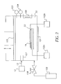
Referring to FIG. 2, controlled environment 30 is designed for use
at extremes of pressure. Incorporated in the controlled environment 30 is a
pressure modulator 105. The pressure modulator 105, as shown, resembles a
piston. This is for illustration only. Skilled artisans will also appreciate that
pressure modulator 105 could also be a pump or a vent used in conjunction with
an additional pressure source. An example of an additional pressure source is the
source 109 of compressed fluid. This source 109 is modulated with a flow control
device or valve 108 to enable functional material to enter the deposition chamber
30 via a fluid delivery path 13. The pressure inside the deposition chamber 30 is
carefully monitored by a pressure sensor 103 and can be set at any pressure less
than that of the delivery system 12 (including levels of vacuum) to facilitate
precipitation/aggregation. In addition, the deposition chamber 30 is provided with
temperature sensor 104 and temperature modulator 106. Temperature modulator
106 is shown as an electric heater but could consist of any of the following (not
shown): heater, a water jacket, a refrigeration coil, and a combination of
temperature control devices.
-
Referring to FIGS. 1, 2, and 4, deposition chamber 30 generally
serves to hold the substrate 14 and the mask 22 and facilitates the deposition of
the precipitated functional material 44. To enable a more complete and even
distribution of the functional material 40, electric or electrostatic charges can be
applied to the substrate 14 and/or mask 22. Through the ejection process in the
discharge assembly 20, the particles are known to become charged. If desired,
additional charge can be applied to them using a particle charging device 107
(FIG. 2). The functional material 40, now charged can be attracted or repelled
from various surfaces to aid in the deposition process. According to FIG. 2,
charging devices 102a, 102b are provided for both the substrate 14 and mask 22,
respectively. For illustrative purposes only, a positive charge (+) is shown on
substrate 14 and a negative charge (-) is shown on mask 22. The polarity may be
changed to suit the application. A charge equal to that of the functional material
40 is applied to the mask 22, whereas a charge opposite of that of the functional
material 40 is applied to the substrate 14 to attract the functional material.
Obviously there can be no electrical conduction between the two to maintain the
charge differential. This may limit the material selection of one or both, or add
the requirement for an additional insulating layer (not shown). In a similar
manner, it may be beneficial to create other electric or electrostatic charges on the
deposition chamber 30 or on any other mechanical elements within the deposition
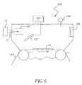
chamber 30. As shown in FIG. 6, an internal baffle 122 may be used to provide a
more even distribution of functional material 40 within the deposition chamber
200. A charge may be applied to the internal baffling by a baffle charging device
123.
-
Referring again to FIG. 2, deposition chamber 30 also provides
easy access for the insertion and removal of the substrate 14 through access port
101. This process will potentially be automated by mechanical devices which are
not shown. Access port 101 of deposition chamber 30 also provides access for the
insertion and removal of the mask 22 as well as for the proper placement of the
mask 22. Mask alignment relative to the substrate 14 is key to this application and
may be manual or preferably, automated. Though it is shown oriented with the
substrate 14 facing upwards, this is not a requirement of the invention. When
attracting particles electrostatically, it may be advantageous to orient the substrate
14 facing downward. In this manner, no debris from the deposition chamber 30
could inadvertently fall onto the substrate 14.
-
The controlled environment can be used for post deposition
processing of the deposited material on the substrate. Post deposition processing
may involve the control of humidity, temperature, atmospheric conditions
including pressure, and chemical composition of the atmosphere. As an example,
many processes require the curing of the materials to obtain desired functionality
at elevated temperature. The thermal control that is already built into the
enclosure can be utilized for this purpose. Alternatively, the post processing
required can be done outside the enclosure.
-
It should be appreciated that deposition chamber 30 should also be
designed so that there are no dead volumes that may result in the accumulation of
precipitated functional materials 44 and so that it may be easily cleaned. As such,
it may be further partitioned into more than one sub-chamber to facilitate the
above (not shown). It may also be equipped with suitable mechanical devices to
aid the precipitation and deposition of functional material 40. An example of such
a device would be a mechanical agitator.
-
Turning now to FIG. 5, another embodiment of deposition chamber
100, contemplated by the invention, is shown. It contains many of the same
features previously described in the discussion of FIG. 2, with the addition of a
medium 111 which divides the deposition chamber 100 into a preparation sub-chamber
100a and a deposition sub-chamber 100b. The materials in these sub-chambers
100a, 100b are allowed to flow through controllable dual chamber
interface valve 110. Each sub-chamber 100a, 100b is configured with
independent control of pressure and temperature through the use of pressure
sensors 103, temperature sensors 104, pressure modulators 105, and temperature
modulators 106. The preparation sub-chamber 100a differs from the formulation
reservoir 18 (FIG. 1) in that the functional material 40 can be (but is not
necessarily) precipitated. The addition of a preparation sub-chamber 100a to the
system allows for a potentially large volume of prepared deposition material to be
ready and maintained at a higher than ambient pressure while still allowing the
changing of substrate 14 and deposition material through the access port 101.
-
In FIG. 6, a simplified deposition chamber 200 is illustrated. In
this embodiment, no provision is made for maintaining a pressure above that of
ambient. Many of the other features described in FIGS. 2 and 5 are still possible,
but by no longer requiring the deposition chamber 200 to support an elevated
pressure, certain additional advantages can be realized. For example, the substrate
14 no longer is required to be contained in deposition chamber 200. This is
illustrated in FIG. 6 by showing a moving substrate in the form of a web 120 that
is transported by conveyors 121. In such a system, it is possible to perform
continuous coating operations. In this case, a separate mask would likely not be
used except for the case of a step and repeat process. Rather, a mask integral to
the substrate, as previously described, is the preferred method of achieving
patterned deposition. Alternatively, a similar approach, illustrated in FIGS. 2 and
5, could be used also without need for access port 101.
-
Additional aspects of the invention may include multiple
deposition chambers 30, 100, or 200, as illustrated in FIGS. 2, 5, and 6, for
coating multiple layers onto substrate 14. Alternatively, multiple masks 22 may
be used such that a mask with a specific configurational structure of aperture
patterns is used and subsequently replaced with another shadow mask of different
configurational structure of aperture patterns on the same substrate 14. Multiple
masks, indexing of a mask, multiple layers, and multiple material processes are
commonly used in the manufacture of displays, therefore details and methods to
provide proper registration such as through the use of optical fiducials are well
known. The sequential process used for deposition of colored material(s) for
display products applications may be interspersed with other processes, including
deposition of other material(s) and/or post treatment of deposited material(s), as
needed, to create a desired product.
-
The system for producing a patterned deposition on a movable
substrate from a compressed fluid, wherein said shadow mask is provided with an
electrical charge forming an electrically charged shadow mask, said electrically
charged shadow mask and said charged precipitate functional material having the
same polarity.
-
The system for producing a patterned deposition on a movable
substrate from a compressed fluid, further comprising means for orienting said
movable substrate relative to a stream of charged precipitate functional material.
-
The system for producing a patterned deposition on a movable
substrate from a compressed fluid, wherein said movable substrate has an
orientation relative to said stream of precipitate functional material that indirectly
exposes said movable substrate to said stream of precipitate functional material.
-
The system for producing a patterned deposition on a movable
substrate from a compressed fluid, wherein said movable substrate has an
orientation relative to said stream of precipitate functional material that exposes
said movable substrate directly to said stream of precipitate functional material.
-
The system for producing a patterned deposition on a movable
substrate from a compressed fluid, wherein said means for controllably delivering
said functional material exposes said precipitate functional material to a pressure
higher than the pressure inside said partial enclosure.
-
The system for producing a patterned deposition on a movable
substrate from a compressed fluid, wherein said pressure modulator is a piston-like
element.
-
The system for producing a patterned deposition on a movable
substrate from a compressed fluid, wherein said pressure modulator is a pump.
-
The system for producing a patterned deposition on a movable
substrate from a compressed fluid, wherein said pressure modulator is a vent
arranged in said partial enclosure and a pressure control means cooperatively
associated with said vent.
-
The system for producing a patterned deposition on a movable
substrate from a compressed fluid, wherein said partial enclosure is further
provided with a first electrostatic charging element for imparting a charge on said
precipitate functional material.
-
The system for producing a patterned deposition on a movable
substrate from a compressed fluid, wherein said partial enclosure is further
provided with a second electrostatic charging element for imparting an
electrostatic charge on said movable substrate.
-
The system for producing a patterned deposition on a movable
substrate from a compressed fluid, wherein said partial enclosure is further
provided with a third electrostatic charging element for imparting an electrostatic
charge on said shadow mask.
-
The system for producing a patterned deposition on a movable
substrate from a compressed fluid, wherein said functional material comprises a
material selected from the group consisting of: electroluminescent molecules,
imaging dyes, ceramic nano-particles, and polymeric materials.
-
The system for producing a patterned deposition on a movable
substrate from a compressed fluid, wherein a charge applied to said movable
substrate is applied for a predetermined duration, said predetermined duration
being determinate of an amount of precipitate functional material deposited on
said movable substrate.
-
The system for producing a patterned deposition on a movable
substrate from a compressed fluid, wherein said compressed fluid comprises a
material selected from the group consisting of: carbon dioxide, nitrous oxide,
ammonia, xenon, ethane, ethylene, propane, propylene, butane, isobutane,
chlorotrifluoromethane, monofluromethane, sulfur hexafluoride, and mixtures
thereof.
-
The system for producing a patterned deposition on a movable
substrate from a compressed fluid, wherein said partial enclosure is
electrostatically charged to prevent deleterious particles from adhering thereto.
-
The system for producing a patterned deposition on a movable
substrate from a compressed fluid, wherein an optical emitter cooperates with an
optical detector determining the concentration of functional material inside said
partial enclosure.
-
The system for producing a patterned deposition on a movable
substrate from a compressed fluid, wherein said partial enclosure has at least one
viewing port for observing activity inside said partial enclosure.
-
The system for producing a patterned deposition on a movable
substrate from a compressed fluid, wherein a reflective surface is arranged in said
partial enclosure opposite said optical emitter for reflecting energy from said
optical emitter that is detected by said optical detector.
-
The system for producing a patterned deposition on a movable
substrate from a compressed fluid, wherein said optical detector transmits an
electrical signal to a microprocessor thereby generating data for future processing.
-
The system for producing a patterned deposition on a movable
substrate from a compressed fluid, wherein said means for controllably delivering
comprises a discharge assembly having a nozzle for ejecting a stream of
precipitate functional material into said partial enclosure.
-
The system for producing a patterned deposition on a movable
substrate from a compressed fluid, wherein said nozzle is a divergent nozzle.
-
The system for producing a patterned deposition on a movable
substrate from a compressed fluid, wherein said precipitate functional material is
further propelled from said nozzle in the presence of an electro-magnetic field in
said partial enclosure.
-
The system for producing a patterned deposition on a movable
substrate from a compressed fluid, wherein said precipitate functional material is
further propelled from said nozzle in the presence of at least one mechanical
shield arranged in said partial enclosure.
-
The system for producing a patterned deposition on a movable
substrate from a compressed fluid, wherein said precipitate functional material is
further propelled from said nozzle in the presence of at least one magnetic lens
arranged in said partial enclosure.
-
The system for producing a patterned deposition on a movable
substrate from a compressed fluid, wherein said precipitate functional material is
further propelled from said nozzle in the presence of at least one electrostatic lens
arranged in said partial enclosure.
-
The system for producing a patterned deposition on a movable
substrate from a compressed fluid, wherein said nozzle is provided with a heating
means to promote a predetermined fluid flow rate.
-
The system for producing a patterned deposition on a movable
substrate from a compressed fluid, wherein said movable substrate and said means
for controllably delivering are spaced apart by a predetermined distance that
enables the compressed fluid to evaporate from a liquid or compressed phase to a
gas phase prior to depositing on said movable substrate.
-
The system for producing a patterned deposition on a movable
substrate from a compressed fluid, wherein said functional material is dissolved in
said compressed state.
-
The system for producing a patterned deposition on a movable
substrate from a compressed fluid, wherein said functional material is dispersed in
said compressed state.
-
It is to be understood that elements not specifically shown or
described may take various forms well known to those skilled in the art.
Additionally, materials identified as suitable for various facets of the invention,
for example, functional materials. These are to be treated as exemplary, and are
not intended to limit the scope of the invention in any manner.