EP1426020A2 - Drug eluting stent graft combination - Google Patents
Drug eluting stent graft combination Download PDFInfo
- Publication number
- EP1426020A2 EP1426020A2 EP03257113A EP03257113A EP1426020A2 EP 1426020 A2 EP1426020 A2 EP 1426020A2 EP 03257113 A EP03257113 A EP 03257113A EP 03257113 A EP03257113 A EP 03257113A EP 1426020 A2 EP1426020 A2 EP 1426020A2
- Authority
- EP
- European Patent Office
- Prior art keywords
- stents
- filter
- catheter
- coating
- vascular
- Prior art date
- Legal status (The legal status is an assumption and is not a legal conclusion. Google has not performed a legal analysis and makes no representation as to the accuracy of the status listed.)
- Withdrawn
Links
Images



Classifications
-
- A—HUMAN NECESSITIES
- A61—MEDICAL OR VETERINARY SCIENCE; HYGIENE
- A61F—FILTERS IMPLANTABLE INTO BLOOD VESSELS; PROSTHESES; DEVICES PROVIDING PATENCY TO, OR PREVENTING COLLAPSING OF, TUBULAR STRUCTURES OF THE BODY, e.g. STENTS; ORTHOPAEDIC, NURSING OR CONTRACEPTIVE DEVICES; FOMENTATION; TREATMENT OR PROTECTION OF EYES OR EARS; BANDAGES, DRESSINGS OR ABSORBENT PADS; FIRST-AID KITS
- A61F2/00—Filters implantable into blood vessels; Prostheses, i.e. artificial substitutes or replacements for parts of the body; Appliances for connecting them with the body; Devices providing patency to, or preventing collapsing of, tubular structures of the body, e.g. stents
- A61F2/02—Prostheses implantable into the body
- A61F2/04—Hollow or tubular parts of organs, e.g. bladders, tracheae, bronchi or bile ducts
- A61F2/06—Blood vessels
- A61F2/07—Stent-grafts
-
- A—HUMAN NECESSITIES
- A61—MEDICAL OR VETERINARY SCIENCE; HYGIENE
- A61F—FILTERS IMPLANTABLE INTO BLOOD VESSELS; PROSTHESES; DEVICES PROVIDING PATENCY TO, OR PREVENTING COLLAPSING OF, TUBULAR STRUCTURES OF THE BODY, e.g. STENTS; ORTHOPAEDIC, NURSING OR CONTRACEPTIVE DEVICES; FOMENTATION; TREATMENT OR PROTECTION OF EYES OR EARS; BANDAGES, DRESSINGS OR ABSORBENT PADS; FIRST-AID KITS
- A61F2/00—Filters implantable into blood vessels; Prostheses, i.e. artificial substitutes or replacements for parts of the body; Appliances for connecting them with the body; Devices providing patency to, or preventing collapsing of, tubular structures of the body, e.g. stents
- A61F2/82—Devices providing patency to, or preventing collapsing of, tubular structures of the body, e.g. stents
- A61F2/86—Stents in a form characterised by the wire-like elements; Stents in the form characterised by a net-like or mesh-like structure
- A61F2/89—Stents in a form characterised by the wire-like elements; Stents in the form characterised by a net-like or mesh-like structure the wire-like elements comprising two or more adjacent rings flexibly connected by separate members
-
- A—HUMAN NECESSITIES
- A61—MEDICAL OR VETERINARY SCIENCE; HYGIENE
- A61F—FILTERS IMPLANTABLE INTO BLOOD VESSELS; PROSTHESES; DEVICES PROVIDING PATENCY TO, OR PREVENTING COLLAPSING OF, TUBULAR STRUCTURES OF THE BODY, e.g. STENTS; ORTHOPAEDIC, NURSING OR CONTRACEPTIVE DEVICES; FOMENTATION; TREATMENT OR PROTECTION OF EYES OR EARS; BANDAGES, DRESSINGS OR ABSORBENT PADS; FIRST-AID KITS
- A61F2230/00—Geometry of prostheses classified in groups A61F2/00 - A61F2/26 or A61F2/82 or A61F9/00 or A61F11/00 or subgroups thereof
- A61F2230/0002—Two-dimensional shapes, e.g. cross-sections
- A61F2230/0028—Shapes in the form of latin or greek characters
- A61F2230/005—Rosette-shaped, e.g. star-shaped
-
- A—HUMAN NECESSITIES
- A61—MEDICAL OR VETERINARY SCIENCE; HYGIENE
- A61F—FILTERS IMPLANTABLE INTO BLOOD VESSELS; PROSTHESES; DEVICES PROVIDING PATENCY TO, OR PREVENTING COLLAPSING OF, TUBULAR STRUCTURES OF THE BODY, e.g. STENTS; ORTHOPAEDIC, NURSING OR CONTRACEPTIVE DEVICES; FOMENTATION; TREATMENT OR PROTECTION OF EYES OR EARS; BANDAGES, DRESSINGS OR ABSORBENT PADS; FIRST-AID KITS
- A61F2230/00—Geometry of prostheses classified in groups A61F2/00 - A61F2/26 or A61F2/82 or A61F9/00 or A61F11/00 or subgroups thereof
- A61F2230/0063—Three-dimensional shapes
- A61F2230/0073—Quadric-shaped
- A61F2230/0078—Quadric-shaped hyperboloidal
-
- A—HUMAN NECESSITIES
- A61—MEDICAL OR VETERINARY SCIENCE; HYGIENE
- A61F—FILTERS IMPLANTABLE INTO BLOOD VESSELS; PROSTHESES; DEVICES PROVIDING PATENCY TO, OR PREVENTING COLLAPSING OF, TUBULAR STRUCTURES OF THE BODY, e.g. STENTS; ORTHOPAEDIC, NURSING OR CONTRACEPTIVE DEVICES; FOMENTATION; TREATMENT OR PROTECTION OF EYES OR EARS; BANDAGES, DRESSINGS OR ABSORBENT PADS; FIRST-AID KITS
- A61F2250/00—Special features of prostheses classified in groups A61F2/00 - A61F2/26 or A61F2/82 or A61F9/00 or A61F11/00 or subgroups thereof
- A61F2250/0058—Additional features; Implant or prostheses properties not otherwise provided for
- A61F2250/0067—Means for introducing or releasing pharmaceutical products into the body
Definitions
- the present invention relates generally to medical devices, and more particularly to a vascular stent graft and delivery system.
- Vascular filters may be used for a variety of therapeutic applications, including implantable vena cava filters for capturing thrombus, or for distal protection during a vascular procedure.
- the present invention relates to a system including a vascular filter or a stent, or a stent graft combination that can be placed inside a body passage or cavity, such as a blood vessel, through a catheter consisting of a tubular basic body with a distal end, a proximal end and a lumen extending in between the ends.
- the device can be received in a compressed state inside the lumen, and the catheter is provided with an ejection device that can be used to eject the vascular filter from the distal end of the catheter.
- the device may be implanted either permanently or temporarily.
- Vascular filters, stents and stent-grafts are often made of an elastic or so-called "memory" material.
- the device Prior to actually positioning the vascular filter or other device according to the known technique inside the blood vessel, the device is arranged in a compressed state in the catheter. By means of an ejection member, the device may be pushed from the open distal tip of the catheter into the blood vessel.
- vascular filters expand from the compressed state inside the catheter lumen to an enlarged or deployed state, when released or deployed at the desired site for treatment. Some vascular filters tend to resiliently expand to that deployed state, which facilitates ejection from the catheter. Also, this resilient outward pressing may resist longitudinal movement from the desired site or compressive external forces.
- vascular filter capable of being more easily positioned accurately, and which tends to proceed smoothly and predictably during deployment.
- the present invention therefore provides a vascular filter for use with a catheter to introduce the filter, wherein a brake is provided.
- the brake acts between the filter and catheter which may tend to control ejection by means of engaging the lumen. This engagement may of course be frictional, and the brake may be provided on the filter or the catheter, or may consist of cooperating components on both filter and catheter.
- an accelerating force exerted by the vascular filter on the distal tip of the catheter can be resisted or even negated by the brake.
- the brake preferably frictionally opposes the movement of the filter out of the catheter. Consequently any expansive accelerating force exerted during ejection of the filter is controlled, at least any particular expansive force which may cause an unexpected longitudinal advance in relation to the distal tip of the catheter.
- the brake may have any of a number of embodiments, as will be discussed in the detailed explanation below which are given by way of example.
- the brake may have been biassed, or the brakes may form a unit with the filter, or may act in unison with additional brakes.
- the vascular filter, stent or graft is covered with an impermeable cover, so as to be able to deliver a drug to the wall of the lumen situated between the stent and the lumen.
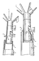
- Figure 1 shows a vascular filter 1 which has been introduced into a blood vessel 2 by means of a catheter 3, which is substantially hollow.
- a catheter 3 which is substantially hollow.
- the filter is pushed along the entire length of the catheter from its proximal end to its distal end, after the catheter distal end has been advanced to the desired position.
- the filter is packed, in a compressed state, in transport packaging forming a covering.
- the vascular filter may be ejected from the distal tip 4 of the catheter 3 by means of a pushing wire 5 and introduced into the blood vessel. Due to release from the radially compressive force imposed by the lumen at the distal tip 4 of the catheter 3, the vascular filter 1 will tend to expand resiliently to obtain an expanded shape.
- the vascular filter illustrated here comprises a number of ribs 6 extending in an axial direction in relation to the blood vessel 2 and along the internal wall hereof. These ribs 6 form an elongated body member. On either side of the ribs 6, filters 7 have been arranged each forming a grid shape. Liquid inside the blood vessel can pass through in an unimpeded fashion, but thrombus will tend to be intercepted by one of the two filters 7.
- An advantage of this configuration is that it provides two chances at intercepting thrombus moving inside the blood vessel.
- the configuration of the ribs 6 which extend along the internal wall of the blood vessel 2 there should be no free ends of ribs which might stick into the internal wall of the blood vessel 2.
- the configuration of the vena cava filter according to the present invention illustrated is consequently designed so as to minimize any distress or damage to the blood vessel inside of which it has been arranged.
- filters 7 have been arranged on either side of the ribs 6, and consequently a symmetrical shape has been obtained, there is no difference in the performance of the filter regarding the direction from which this vascular filter 1 has been placed inside the blood vessel 2.
- each of the filters 7 is such that each of the ribs 6 is connected with a number of the components of these filters. Furthermore, each of the ribs 6 is connected with both filters 7 on either side. Due to this configuration, an added safety feature is that one of the ribs 6 or a component of one of the filters 7 may even break without a part of the filter 1 separating as a consequence.
- tipping over or misalignment of either filter is less likely due to the more or less tubular shape into which the ribs 6 have been arranged, so that positioning of the vascular filter 1 inside the blood vessel 2 can take place with unprecedented stability and reliability.
- the vascular filter 1 is preferably made of a very resilient material, like nitinol. Following ejection from the distal tip 4 of the catheter 3, filter 1 can expand and will be wedged against the internal wall 8 of the blood vessel 2.
- two projections 9 form a resilient brake, arranged close to the proximal end of the vascular filter 1. These resilient projections 9 serve in particular to control ejection of the proximal section of the filter 1.
- the projections 9 push against the inside of the catheter lumen close to the distal end of the catheter 3.
- the proximal filter 7 may tend to exert a force on the distal edge of the catheter 3 during ejection of the filter 1. In this way the projections 9 slow down the rate of expansion, and thus control the expansive force of the filter 7.
- accuracy when positioning a vascular filter according to the present invention may be improved.
- the projections 9 have been biassed and extend in an outward radial direction in relation to the proximal end section of the filter 1, so that they push against the internal wall of the catheter 3, before escaping from the catheter themselves. These outwardly directed projections 9 consequently cause a braking force on the internal wall of the catheter 3, which is also directed outwards, so that control of the ejection of the filter 1 is effected.
- the projections 9 form a unit with the filter 1, in the sense that each of the projections 9 has been made of material from the filter 1 located in between closely arranged cuts 10. The strips of material from the cuts 10 have subsequently been biassed.
- the filter 1 shown in the Figures has been made of a cylindrical unit.
- the filter may have been made from a plate-like unit or from an assembly of riblike elements. Other options are possible as well.
- the filter may have been made of a resilient material, such as nitinol, which expands into the filter 1 with the shape illustrated here, following ejection of the cylindrical body 1'.
- different types of memory materials, or other shape-memory metals may be used.
- the projections 9 are positioned radially opposite each other near to the proximal end of the filter 1, so that as a consequence a more uniformly distributed force is exerted on the internal wall of the catheter 3.
- more than two projections 9 may be employed.
- the action of the projections 9, which push from the proximal end of the filter 1 against the internal wall of the distal end 4 of the catheter 3, has been illustrated schematically.
- this braking effect is preferably present especially during the release and expansion of the proximal filter 7 of the vena cava filter 1 according to the present invention.
- the projections 9 tend to slow down the ejection speed of the vascular filter 1, which is caused by elements of the proximal filter 7 pushing off against the extreme edge of the catheter 3 at the distal end hereof.
- Figure 3 shows the situation illustrated in Figure 2 during a slightly later stage, and it is clear that the projections 9 pushed against the internal wall of the catheter 3 with a certain force. This situation is evidenced by confirming that the projections 9 protrude more than the internal dimensions of the catheter 3, in the state illustrated in Figure 3. The compression of the projections 9 illustrated in 2 consequently ensures that a braking force is exerted on the internal wall of the catheter 3, which tends to control expansion of the proximal filter 7.
- the brake is formed as a single loop 11.
- the loop 11 is resilient in the sense that it has a tendency to expand from the state drawn with continuous lines, in the direction indicated by arrow A, into the state drawn with dotted lines.
- the loop 11 has been illustrated in a state which corresponds to transportation inside the catheter 3 to the desired position.
- the state of the loop 11 indicated with dotted lines corresponds to the relaxed situation, in which the vascular filter 1 has been ejected into the blood vessel.
- This last situation has been illustrated in greater detail in Figure 5, in which the vascular filter 1 and the proximal filter 7 with its loop 11 have expanded in a controlled manner.
- loop 11 may be used to later remove the vascular filter 1. Loop 11 can thus serve as a target for a hook-shaped extraction element, in order to remove the vascular filter 1.
- the hook-shaped extraction body (not shown) may engage the loop 11, and pull the entire vascular filter 1 back into a catheter enveloping the extraction element.
- vascular filter which has a different shape than the one described above. It is also possible to use a more conventional vascular filter without the double filter-function.
- the vascular filter also does not need to comprise ribs extending in an axial direction in relation to the blood vessel.
- one or more removal members may be added at the distal end of the vascular filter, which may have been embodied in the shape of a hook or a loop. Such a removal member can be gabbed from the other side or the distal side such that removal of the filter is possible.
- vascular filters or stents 11 according to the present invention are illustrated.
- the vascular filters 11 have just been introduced into a blood vessel 2 by means of a catheter 3, which is substantially hollow.
- a catheter 3 which is substantially hollow.
- the distal tip 4 of the catheter 3 at least one vascular filter was initially arranged in a compressed state.
- the filter or stent is pushed along the entire length of the catheter from its proximal end to its distal end, after the catheter distal end has been advanced to the desired position.
- the filter is packed, in a compressed state, in transport packaging forming a covering.
- the vascular filter may be ejected from the distal tip 4 of the catheter 3 by means of a pushing wire 5 and introduced into the blood vessel. Due to release from the radially compressive force imposed by the lumen at the distal tip 4 of the catheter 3, the vascular filter or stent 11 will tend to expand resiliently to obtain an expanded shape.
- the stent 11 illustrated here comprises a number of ribs 6 extending in an axial direction in relation to the blood vessel 2 and along the internal wall hereof. These ribs 6 form an elongated body member. Due to the configuration of the ribs 6 which extend along the internal wall of the blood vessel 2, there should be no free ends of ribs that might stick into the internal wall of the blood vessel 2. In addition, tipping over or misalignment of either filter is less likely due to the more or less tubular shape into which the ribs 6 have been arranged, so that positioning of the vascular filter 1 inside the blood vessel 2 can take place with unprecedented stability and reliability.
- the vascular filter or stent 11 is preferably made of a very resilient material such as a shape memory alloy, especially nitinol. Following ejection from the distal tip 4 of the catheter 3, filter 1 can expand and will be wedged against the internal wall 8 of the blood vessel 2.
- the stents 11 contain between themselves a cover 20.
- This cover 20 is made of any conventional graft material, especially with low friction characteristics, for example a polyester such as that sold under the trade mark Dacron, or a fluorinated polyolefin, especially a polytetrafluoroethylene such as that sold under the trade mark Teflon.
- the cover 20 is impregnated with a drug coated controlled release polymer, so that a therapeutic amount of the drug can be released into the wall of the lumen.
- a drug coated controlled release polymer Some exemplary drugs that are useful are rapamycin, paclitaxel, and any analgesic such as acetaminophen.
- the polymer coating techniques that are useful to embed the coating into the cover 20 are known, such as those disclosed in WO-A-01/87342.
Landscapes
- Health & Medical Sciences (AREA)
- Heart & Thoracic Surgery (AREA)
- Animal Behavior & Ethology (AREA)
- Cardiology (AREA)
- Oral & Maxillofacial Surgery (AREA)
- Transplantation (AREA)
- Engineering & Computer Science (AREA)
- Biomedical Technology (AREA)
- Gastroenterology & Hepatology (AREA)
- Pulmonology (AREA)
- Vascular Medicine (AREA)
- Life Sciences & Earth Sciences (AREA)
- General Health & Medical Sciences (AREA)
- Public Health (AREA)
- Veterinary Medicine (AREA)
- Prostheses (AREA)
- Surgical Instruments (AREA)
- Media Introduction/Drainage Providing Device (AREA)
- Materials For Medical Uses (AREA)
Abstract
Description
Claims (6)
- A device for delivery through a catheter to a desired site in a body vessel for therapeutic treatment of a patient, comprising:a pair of stents having a compressed shape and an expanded shape, and the stents tending to resiliently expand from the compressed shape to the expanded shape, such that when the stents are positioned at the desired site and immersed in a body fluid flowing past the desired site, the stents allow passage of body fluid; anda cover connecting said stents, said cover embedded with a coating wherein the coating is impregnated with a drug on its outer surface, such that when the stents expand against the surface of a lumen, it forces said drug against the lumen walls.
- The device as set forth in claim 1, wherein at least a portion of the stents comprises a shape memory alloy.
- The device as set forth in claim 1, wherein said coating comprises a low friction polymer, preferably a fluorinated polyolefin.
- The device of claim 1 wherein the stents are self-expanding.
- The device of claim 1 wherein the stents have a pair of ends and a centre, wherein the centre has a lower self expanding force than the ends, so that the ends expand against the wall surface and leave the drug on said coating trapped against the centre of the stent.
- The device of claim 6 wherein the coating a low friction polymer, preferably a fluorinated polyolefin.
Applications Claiming Priority (2)
| Application Number | Priority Date | Filing Date | Title |
|---|---|---|---|
| US291996 | 2002-11-12 | ||
| US10/291,996 US20040093064A1 (en) | 2002-11-12 | 2002-11-12 | Drug eluting stent graft combination |
Publications (2)
| Publication Number | Publication Date |
|---|---|
| EP1426020A2 true EP1426020A2 (en) | 2004-06-09 |
| EP1426020A3 EP1426020A3 (en) | 2005-06-22 |
Family
ID=32229342
Family Applications (1)
| Application Number | Title | Priority Date | Filing Date |
|---|---|---|---|
| EP03257113A Withdrawn EP1426020A3 (en) | 2002-11-12 | 2003-11-11 | Drug eluting stent graft combination |
Country Status (5)
| Country | Link |
|---|---|
| US (1) | US20040093064A1 (en) |
| EP (1) | EP1426020A3 (en) |
| JP (1) | JP2004160233A (en) |
| AU (1) | AU2003261557A1 (en) |
| CA (1) | CA2448942A1 (en) |
Cited By (1)
| Publication number | Priority date | Publication date | Assignee | Title |
|---|---|---|---|---|
| US9867727B2 (en) | 1998-02-09 | 2018-01-16 | Trivascular, Inc. | Endovascular graft |
Families Citing this family (25)
| Publication number | Priority date | Publication date | Assignee | Title |
|---|---|---|---|---|
| US7314477B1 (en) | 1998-09-25 | 2008-01-01 | C.R. Bard Inc. | Removable embolus blood clot filter and filter delivery unit |
| US9204956B2 (en) | 2002-02-20 | 2015-12-08 | C. R. Bard, Inc. | IVC filter with translating hooks |
| US7704267B2 (en) | 2004-08-04 | 2010-04-27 | C. R. Bard, Inc. | Non-entangling vena cava filter |
| ATE483716T1 (en) * | 2004-08-27 | 2010-10-15 | Cordis Corp | SOLVENT-FREE AMORPHIC RAPAMYCIN |
| US20060165667A1 (en) * | 2004-12-03 | 2006-07-27 | Case Western Reserve University | Novel methods, compositions and devices for inducing neovascularization |
| US12115057B2 (en) | 2005-05-12 | 2024-10-15 | C.R. Bard, Inc. | Tubular filter |
| WO2006124405A2 (en) | 2005-05-12 | 2006-11-23 | C.R. Bard Inc. | Removable embolus blood clot filter |
| JP4851522B2 (en) | 2005-08-09 | 2012-01-11 | シー・アール・バード・インコーポレーテッド | Insertion type thrombus filter and delivery system |
| JP2009519731A (en) | 2005-11-18 | 2009-05-21 | シー・アール・バード・インコーポレイテツド | Vena cava filter with filament |
| US10188496B2 (en) | 2006-05-02 | 2019-01-29 | C. R. Bard, Inc. | Vena cava filter formed from a sheet |
| US9326842B2 (en) | 2006-06-05 | 2016-05-03 | C. R . Bard, Inc. | Embolus blood clot filter utilizable with a single delivery system or a single retrieval system in one of a femoral or jugular access |
| US8007470B2 (en) * | 2007-07-10 | 2011-08-30 | Cook Medical Technologies Llc | Minimally invasive medical device and method for delivery of therapeutic or diagnostic agents into a vessel wall |
| US8066755B2 (en) | 2007-09-26 | 2011-11-29 | Trivascular, Inc. | System and method of pivoted stent deployment |
| US8226701B2 (en) | 2007-09-26 | 2012-07-24 | Trivascular, Inc. | Stent and delivery system for deployment thereof |
| US8663309B2 (en) | 2007-09-26 | 2014-03-04 | Trivascular, Inc. | Asymmetric stent apparatus and method |
| US10159557B2 (en) | 2007-10-04 | 2018-12-25 | Trivascular, Inc. | Modular vascular graft for low profile percutaneous delivery |
| US8083789B2 (en) | 2007-11-16 | 2011-12-27 | Trivascular, Inc. | Securement assembly and method for expandable endovascular device |
| US8328861B2 (en) | 2007-11-16 | 2012-12-11 | Trivascular, Inc. | Delivery system and method for bifurcated graft |
| JP5685253B2 (en) | 2009-07-29 | 2015-03-18 | シー・アール・バード・インコーポレーテッドC R Bard Incorporated | Tubular filter |
| CN101843531A (en) * | 2010-05-25 | 2010-09-29 | 天健医疗科技(苏州)有限公司 | Medicament coated thrombus filter |
| EP2663256A1 (en) * | 2011-01-13 | 2013-11-20 | Innovia LLC | Endoluminal drug applicator and method of treating diseased vessels of the body |
| US8992595B2 (en) | 2012-04-04 | 2015-03-31 | Trivascular, Inc. | Durable stent graft with tapered struts and stable delivery methods and devices |
| US9498363B2 (en) | 2012-04-06 | 2016-11-22 | Trivascular, Inc. | Delivery catheter for endovascular device |
| CN103961191A (en) * | 2014-04-29 | 2014-08-06 | 天津博安医用有限公司 | Vena cava filter device capable of releasing thrombolytic drug |
| CN116439876B (en) | 2023-05-06 | 2024-06-04 | 苏州中天医疗器械科技有限公司 | Remote protector and manufacturing method thereof |
Family Cites Families (6)
| Publication number | Priority date | Publication date | Assignee | Title |
|---|---|---|---|---|
| US5078726A (en) * | 1989-02-01 | 1992-01-07 | Kreamer Jeffry W | Graft stent and method of repairing blood vessels |
| US6124523A (en) * | 1995-03-10 | 2000-09-26 | Impra, Inc. | Encapsulated stent |
| US6193745B1 (en) * | 1995-10-03 | 2001-02-27 | Medtronic, Inc. | Modular intraluminal prosteheses construction and methods |
| US6168619B1 (en) * | 1998-10-16 | 2001-01-02 | Quanam Medical Corporation | Intravascular stent having a coaxial polymer member and end sleeves |
| US6402779B1 (en) * | 1999-07-26 | 2002-06-11 | Endomed, Inc. | Balloon-assisted intraluminal stent graft |
| US6776796B2 (en) * | 2000-05-12 | 2004-08-17 | Cordis Corportation | Antiinflammatory drug and delivery device |
-
2002
- 2002-11-12 US US10/291,996 patent/US20040093064A1/en not_active Abandoned
-
2003
- 2003-11-11 AU AU2003261557A patent/AU2003261557A1/en not_active Abandoned
- 2003-11-11 EP EP03257113A patent/EP1426020A3/en not_active Withdrawn
- 2003-11-11 JP JP2003381496A patent/JP2004160233A/en active Pending
- 2003-11-12 CA CA002448942A patent/CA2448942A1/en not_active Abandoned
Cited By (2)
| Publication number | Priority date | Publication date | Assignee | Title |
|---|---|---|---|---|
| US9867727B2 (en) | 1998-02-09 | 2018-01-16 | Trivascular, Inc. | Endovascular graft |
| US10548750B2 (en) | 1998-02-09 | 2020-02-04 | Trivascular, Inc. | Endovascular graft |
Also Published As
| Publication number | Publication date |
|---|---|
| AU2003261557A1 (en) | 2004-05-27 |
| CA2448942A1 (en) | 2004-05-12 |
| JP2004160233A (en) | 2004-06-10 |
| EP1426020A3 (en) | 2005-06-22 |
| US20040093064A1 (en) | 2004-05-13 |
Similar Documents
| Publication | Publication Date | Title |
|---|---|---|
| US20040093064A1 (en) | Drug eluting stent graft combination | |
| US6099549A (en) | Vascular filter for controlled release | |
| US6264671B1 (en) | Stent delivery catheter and method of use | |
| US9693851B2 (en) | Filter delivery system | |
| EP1718242B1 (en) | Centering intravascular filters | |
| US8088154B2 (en) | Medical device delivery system with sheath separation | |
| US6241746B1 (en) | Vascular filter convertible to a stent and method | |
| US7736385B2 (en) | Exchangeable delivery system with distal protection | |
| EP1220648B1 (en) | Removable thrombus filter | |
| JP4680193B2 (en) | Suppression mechanism and manufacturing method thereof | |
| US8025675B2 (en) | Temporary filter device | |
| US9125765B2 (en) | Implant deployment restraint device | |
| EP1346703A1 (en) | Releasable and retrievable vascular filter system | |
| US20060184225A1 (en) | Force distributing system for delivering a self-expanding stent | |
| AU5152500A (en) | Stent delivery system for prevention of kinking, and method of loading and using same | |
| US5855599A (en) | Silicon micro machined occlusion implant | |
| EP2777643A1 (en) | Implant introducer with helical trigger wire | |
| US20080275487A1 (en) | Removable medical filter with stand-off arms | |
| CN117297848A (en) | Release system for self-expanding endoprosthesis | |
| US20100222862A1 (en) | Stent, Stent Graft and Other Implantable Assemblies | |
| KR20240154059A (en) | Flexible features for color transfer deployment |
Legal Events
| Date | Code | Title | Description |
|---|---|---|---|
| PUAI | Public reference made under article 153(3) epc to a published international application that has entered the european phase |
Free format text: ORIGINAL CODE: 0009012 |
|
| AK | Designated contracting states |
Kind code of ref document: A2 Designated state(s): AT BE BG CH CY CZ DE DK EE ES FI FR GB GR HU IE IT LI LU MC NL PT RO SE SI SK TR |
|
| AX | Request for extension of the european patent |
Extension state: AL LT LV MK |
|
| PUAL | Search report despatched |
Free format text: ORIGINAL CODE: 0009013 |
|
| AK | Designated contracting states |
Kind code of ref document: A3 Designated state(s): AT BE BG CH CY CZ DE DK EE ES FI FR GB GR HU IE IT LI LU MC NL PT RO SE SI SK TR |
|
| AX | Request for extension of the european patent |
Extension state: AL LT LV MK |
|
| 17P | Request for examination filed |
Effective date: 20051122 |
|
| AKX | Designation fees paid |
Designated state(s): AT BE BG CH CY CZ DE DK EE ES FI FR GB GR HU IE IT LI LU MC NL PT RO SE SI SK TR |
|
| 17Q | First examination report despatched |
Effective date: 20070925 |
|
| R17C | First examination report despatched (corrected) |
Effective date: 20080107 |
|
| STAA | Information on the status of an ep patent application or granted ep patent |
Free format text: STATUS: THE APPLICATION IS DEEMED TO BE WITHDRAWN |
|
| 18D | Application deemed to be withdrawn |
Effective date: 20080520 |