EP1425890B1 - Power source regulation along a transmission line with feedback loop - Google Patents
Power source regulation along a transmission line with feedback loop Download PDFInfo
- Publication number
- EP1425890B1 EP1425890B1 EP02759322A EP02759322A EP1425890B1 EP 1425890 B1 EP1425890 B1 EP 1425890B1 EP 02759322 A EP02759322 A EP 02759322A EP 02759322 A EP02759322 A EP 02759322A EP 1425890 B1 EP1425890 B1 EP 1425890B1
- Authority
- EP
- European Patent Office
- Prior art keywords
- voltage
- feedback
- source
- impedance
- signal
- Prior art date
- Legal status (The legal status is an assumption and is not a legal conclusion. Google has not performed a legal analysis and makes no representation as to the accuracy of the status listed.)
- Expired - Lifetime
Links
Images


Classifications
-
- E—FIXED CONSTRUCTIONS
- E21—EARTH OR ROCK DRILLING; MINING
- E21B—EARTH OR ROCK DRILLING; OBTAINING OIL, GAS, WATER, SOLUBLE OR MELTABLE MATERIALS OR A SLURRY OF MINERALS FROM WELLS
- E21B47/00—Survey of boreholes or wells
- E21B47/12—Means for transmitting measuring-signals or control signals from the well to the surface, or from the surface to the well, e.g. for logging while drilling
-
- H—ELECTRICITY
- H04—ELECTRIC COMMUNICATION TECHNIQUE
- H04L—TRANSMISSION OF DIGITAL INFORMATION, e.g. TELEGRAPHIC COMMUNICATION
- H04L25/00—Baseband systems
- H04L25/02—Details ; arrangements for supplying electrical power along data transmission lines
Definitions
- the present invention generally relates to the field of data acquisition systems and more particularly to a wireline logging system and method that includes dynamic control of the power supplied to a load based upon a model of the wireline system.
- Wireline logging refers generally to the surveying of oil or gas wells to determine their geological, petro-physical, or geophysical properties using electronic measuring instruments.
- the electronic instruments are conveyed into a wellbore with an armored steel cable, referred to as a wireline cable. Measurements made by downhole instruments secured to the wireline cable are transmitted back to a data processing system located at the surface through electrical conductors in the wireline cable. Electrical, acoustical, nuclear and imaging tools are used to stimulate the formations and fluids within the wellbore and the electronic measuring instruments then measure the response of the formations and fluids.
- the wireline cable provides also the electrical power required by the logging tools to operate.
- a wireline logging system may be viewed as an electrical circuit comprising a head resistance (Rh) representing the downhole instruments in series with an impedance element representing the wireline cable itself.
- Rh head resistance
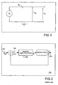
- FIG 1 illustrates a circuit diagram of the system. In this simple model, a voltage source Vs is applied across the series combination of the cable resistance (Rc) and the head resistance Rh.
- Voltage regulation system 120 compares a measured value of the load voltage V L 122 against a set voltage V set 124 to determine an error signal 126. Error signal 126 is indicative of the difference between V L 122 and the V set 124. Error signal 126 is then typically provided to an error amplification element 128.
- Amplification element 128 typically includes an operational amplifier and may employ a proportional, integrating, and/or differentiating circuit depending upon the application. Amplification element 128 typically generates a source voltage V s from error signal 126 to maintain V L at the desired level (i.e., V set ).
- a conventional voltage regulator such as system 120 requires an accurate measurement of the load voltage V L to implement the voltage control at the voltage source.
- V L load voltage
- feeding the load voltage back to the regulator circuitry presents no significant problem.
- it is logistically impracticable to feed the load voltage back to the source because of the tremendous length of contemporary wireline cables.
- it would be highly desirable to implement a voltage control system that could be suitably employed in a wireline logging application and other applications characterized by great distances between the load and the voltage regulator. This system would preferably allow the operation of the cable at or near its maximum power carrying capacity, while minimizing the voltage variation at the input of the electronic circuits powered. It would be further desirable if the implemented solution did not substantially increase the cost or complexity of the wireline logging operation.
- EP0689300 discloses apparatus for compensating centralized remote signal attenuation in power lines.
- the apparatus includes a selection circuit which detects the centralized remote control signals, and effectively re-injects them into the power lines.
- a control circuit detects the re-injected signals, and uses feedback to adjust them to have the correct remote control injection level.
- the present invention contemplates a system and method for controlling voltage at a load, such as the load at the end of a wireline cable, that is distant and effectively inaccessible from the control circuit.
- the invention incorporates a feedback unit configured to model the short circuit input impedance of the wireline cable itself.
- the current from the system's voltage source is provided to the feedback unit to create a feedback voltage that approximates the voltage drop that occurs along the cable.
- This feedback voltage is added to a set voltage where the set voltage equals the desired load voltage.
- the invention uses positive feedback to control the load voltage in an environment when the load voltage itself cannot be effectively measured.
- the system includes a control mechanism in which a signal measured at the voltage source provides the input to a circuit that models the impedance characteristics of the wireline cable.
- the output of the model circuit represents an approximation of the measured signal's effect on the load voltage in the actual wireline cable. This approximation is then used to alter the source voltage to cancel the effect on the load voltage caused by the cable's impedance.
- the signal that provides the input to the cable model circuit is the source current.
- the cable model circuit represents the short circuit input impedance of the cable, that is, the impedance of the cable when the load end of the cable is short circuited. This impedance may be measured empirically by characterizing the cable or by including the necessary measurement circuits into the system itself.
- the circuit When the source current is provided to this cable model circuit, the circuit generates a voltage offset signal that is representative of the voltage loss in the wireline cable. By adding this offset voltage to a set voltage, the voltage control system maintains the load voltage at the set voltage.
- a compensation circuit may be included in the feedback loop to improve the transient response and stability of the system.
- the source current is equal to the load current.
- the wireline cable introduces signal loss and time delay into the system.
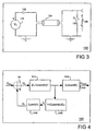
- FIG 3 a circuit model of a wireline cable system 130 that includes a transmission line element 134 representing the wireline cable is depicted.
- the characteristic impedance of transmission line 134 is denoted as Z 0 .
- V H V S / cosh ⁇ ⁇ l ⁇ Z H / Z H + Z 0 ⁇ tanh ⁇ ⁇ l
- I S V S / Z 0 ⁇ Z 0 / Z H ⁇ tanh ⁇ ⁇ l / Z H + Z 0 ⁇ tanh ⁇ ⁇ l
- l is the length of transmission cable 134 and ⁇ is the cable's propagation constant.
- the input impedance of the transmission cable when the load or distal end is short circuited is denoted herein as the short circuit input impedance Z is .
- the short circuit input impedance Z Z 0 tanh(K).
- V H V set .
- Equation 6 suggests that one may maintain the load voltage V H at approximately a desired voltage (V set ) by driving the wireline cable with a voltage (Vs) equal to V set plus a feedback voltage, where the feedback voltage is a function of the voltage source current (I s ).
- V set a desired voltage
- Vs voltage
- I s voltage source current
- the cosh(K) factor is approximately equal to 1 and the load voltage V H is substantially equal to V set .
- the cosh(K) factor represents transmission line losses and delay. While the line losses can be compensated for, compensating for delay could be achieved only if the current variations are anticipated. Since this is a theoretical impossibility, the cosh(K) factor does place a limit on the maximum frequency at which the feedback unit can track changes in the load impedance. Nevertheless, because the voltage source current Is is readily measurable at the surface, Equation 6 implies a control circuit that is useful over a wide range of frequencies and does not require a value, such as the load voltage, that
- a canonical model of a wireline logging system employing the feedback control suggested by Equation 6 is presented.
- a power supply 141 or other voltage source drives the wireline cable with a source voltage V S .
- the relationship between the load voltage V H and the source voltage V S as indicated in Equation 1 is reflected by blocks 143 and 144.
- the relationship between the source current Is and the source voltage V S according to Equation 2 above is reflected in blocks 143 and 145.
- blocks 143, 144, and 145 do not correspond to physical circuits in the system, but instead represent the relationship between the various input and output parameters of the system.
- the feedback voltage V F is added to a set voltage V set to produce the source voltage V S that drives the wireline cable.
- the short circuit line impedance Z is can be determined empirically during cable characterization, or the necessary circuits may be included in the system to perform the required measurement(s) at power up or periodically during operation.
- the feedback voltage V F approximates the voltage drop along the transmission line at the source current. By adding this voltage drop to the set voltage V set , the load voltage is maintained at approximately the set voltage where the approximation is highly accurate at steady state and low frequency conditions.
- a Nyquist plot is determined for an actual wireline cable loaded with a resistor that matches the resistance of the wireline, the plot would enclose the -1 point on the complex plane thereby indicating instability.
- a pole in the feedback loop can provide the necessary stability compensation.
- system 150 includes a set point unit 152 that generates a controlled voltage V set .
- Set point unit 152 may be implemented with a Zener diode circuit or any other suitable technique for generating an analog reference voltage signal.
- set point unit 152 may simply generate a signal indicative of V set rather than producing an actual voltage. If, for example, portions of system 150 are implemented with a digital signal processor (DSP), set point unit 152 may comprise a portion of the DSP that generates a digital value representative of V set . This digital value could be converted to V set by a digital-to-analog converter (DAC) or provided directly to a digitally controlled power source.
- DSP digital signal processor
- DAC digital-to-analog converter
- the output of set point unit 152 provides a first input to an adder unit 153.
- Adder unit 153 receives a second input from the output of a feedback unit 155 that generates a feedback voltage signal indicative of the feedback voltage V F .
- adder unit 153 may comprise a portion of a DSP that produces a signal comprising a digital value that is indicative of a corresponding voltage.
- Adder unit 153 generates a voltage signal 157 that provides an input to a power source.
- power source 154 is a modulating power supply that produces an output voltage V S that is proportional to the input voltage.
- power source 154 may be implemented as a switching mode power supply (also referred to as a switching converter) that provides a power supply function using low loss components such as capacitors, inductors, and transformers, and a set of 2-state switches.
- Power source 154 may be a digitally controlled power source.
- the voltage signal 157 may comprise a digital value indicative of a voltage rather than an actual voltage level.
- the feedback unit 155 is driven by the source current Is generated by power source 154.
- Feedback unit 155 generates a feedback voltage signal.
- the feedback voltage signal may be an analog signal having a voltage equal to the feedback voltage V F .
- the feedback voltage signal may comprise a digital value that is indicative of the feedback voltage V F .
- feedback unit 155 includes, a current measurement module 161, an impedance element 156, and a frequency compensation element 158.
- Current measurement module 161 includes a circuit that determines the magnitude of the source current Is and provides a signal to impedance element 156 that indicates the determined current.
- the impedance element 156 is designed to have an impedance that closely matches the short circuit input impedance Z is of the wireline cable.
- impedance element 156 may model the DC component of the short circuit input impedance (i.e., the DC resistance). This implementation represents a tradeoff in performance for simplicity and cost of implementation.
- the stability compensation element 158 is designed to improve the transient response and stability of the circuit.
- Feedback unit 155 may be entirely or partially implemented with a suitably programmed DSP. Referring to FIG 6 , a representative schematic of a circuit 160 suitable for implementing the system 150 of FIG 5 is depicted. In the depicted embodiment, current measurement module 161 of FIG.
- module 161 is implemented with a low ohm resistor, such as 1 ⁇ resistor 162 tied between the transmission cable 134 and ground such that the voltage across resistor 162 in volts is equal to the source current I S in amperes.
- the depicted embodiment of module 161 further includes operational amplifier circuit that provides an inverting and isolation function that is specific to the depicted implementation.
- the impedance element 156 of FIG. 5 is implemented as an RLC circuit 166 that models the short circuit line impedance of the wireline cable. The output of circuit 166 is combined via resistor 170 with a reference voltage.
- the reference voltage circuit includes the 15V voltage sources and their corresponding capacitors. Without the feedback voltage generated by RLC circuit 166, the resistors 174 and 176 produce a reference voltage (V set ) on node 172 under steady state conditions. With the feedback voltage generated by circuit 166, node 172 varies around the set voltage in response changes in the source current Is.
- the voltage source node 178 which represents the source voltage V S that drives the wireline cable mirrors the voltage on node 172 such that, as the voltage of node 172 varies in response to varying values of feedback voltage, the source voltage V S on node 178 varies as well.
- the integrator circuit 168 provides stability compensation. When the load impedance varies significantly, the source current increase or decrease will cause a corresponding increase or decrease in the feedback voltage, which causes the source voltage to increase or decrease to keep the load voltage at a relatively constant value.
- circuit elements depicted in FIG 6 may be implemented with more advanced technology than the discrete components depicted.
- a DSP for example, could be implemented to optimize circuit response time and stability.
- the DSP could, for example, provide a more accurate replication of the wireline cable impedance and the stability circuitry.
- alternative embodiments of the invention may employ proportional, differential, or integrating feedback elements in feedback unit 155.
- load voltage variations could be further limited by employing a passive low pass filter 159 between the cable and load impedance Z H or in parallel with the load impedance that would slow down the effects of fast load impedance Z H changes.
Landscapes
- Engineering & Computer Science (AREA)
- Geology (AREA)
- Physics & Mathematics (AREA)
- Mining & Mineral Resources (AREA)
- Life Sciences & Earth Sciences (AREA)
- Computer Networks & Wireless Communication (AREA)
- Fluid Mechanics (AREA)
- Environmental & Geological Engineering (AREA)
- Geophysics (AREA)
- General Life Sciences & Earth Sciences (AREA)
- Geochemistry & Mineralogy (AREA)
- Power Engineering (AREA)
- Remote Sensing (AREA)
- Signal Processing (AREA)
- Arrangements For Transmission Of Measured Signals (AREA)
- Control Of Voltage And Current In General (AREA)
- Cable Transmission Systems, Equalization Of Radio And Reduction Of Echo (AREA)
- Surgical Instruments (AREA)
- Amplifiers (AREA)
- Measurement And Recording Of Electrical Phenomena And Electrical Characteristics Of The Living Body (AREA)
- Electrotherapy Devices (AREA)
- Control Of Metal Rolling (AREA)
- Dc Digital Transmission (AREA)
- Direct Current Feeding And Distribution (AREA)
Abstract
Description
- The present invention generally relates to the field of data acquisition systems and more particularly to a wireline logging system and method that includes dynamic control of the power supplied to a load based upon a model of the wireline system.
- Wireline logging refers generally to the surveying of oil or gas wells to determine their geological, petro-physical, or geophysical properties using electronic measuring instruments. The electronic instruments are conveyed into a wellbore with an armored steel cable, referred to as a wireline cable. Measurements made by downhole instruments secured to the wireline cable are transmitted back to a data processing system located at the surface through electrical conductors in the wireline cable. Electrical, acoustical, nuclear and imaging tools are used to stimulate the formations and fluids within the wellbore and the electronic measuring instruments then measure the response of the formations and fluids. The wireline cable provides also the electrical power required by the logging tools to operate.
- From an electric power perspective, a wireline logging system may be viewed as an electrical circuit comprising a head resistance (Rh) representing the downhole instruments in series with an impedance element representing the wireline cable itself. If the wireline cable is modeled as a simple resistive element,
FIG 1 illustrates a circuit diagram of the system. In this simple model, a voltage source Vs is applied across the series combination of the cable resistance (Rc) and the head resistance Rh. - Two competing considerations govern wireline logging operations. On the one hand, it is desirable to maximize the power delivered to the head (tools) to maximize the rate of data acquisition and speed up operations in general. It is well known that maximum power is delivered to the load when the cable resistance Rc equals the head resistance Rh and the voltage at the head Vh is 1/2 the source voltage Vs. Under these conditions, however, the load voltage Vh varies by approximately 100% when the load impedance (Rh) goes from this minimum value to almost open circuit, which occurs when heavy loads are disconnected and only the control circuits remain powered. This variation is typically unacceptable for electronic circuits in general, and in wireline logging systems in particular. Some means of regulating the voltage supplied to the head is therefore required.
- Referring now to
FIG 2 , a block diagram representing a traditionalvoltage regulation system 120 is illustrated.Voltage regulation system 120 compares a measured value of theload voltage V L 122 against aset voltage V set 124 to determine anerror signal 126.Error signal 126 is indicative of the difference betweenV L 122 and theV set 124.Error signal 126 is then typically provided to an error amplification element 128. Amplification element 128 typically includes an operational amplifier and may employ a proportional, integrating, and/or differentiating circuit depending upon the application. Amplification element 128 typically generates a source voltage Vs fromerror signal 126 to maintain VL at the desired level (i.e., Vset). - A conventional voltage regulator such as
system 120 requires an accurate measurement of the load voltage VL to implement the voltage control at the voltage source. In many applications where the load is located in proximity to the source voltage, feeding the load voltage back to the regulator circuitry presents no significant problem. In a wireline logging application, unfortunately, it is logistically impracticable to feed the load voltage back to the source because of the tremendous length of contemporary wireline cables. Even if the wireline cable were constructed to include a feedback cable to carry the load voltage signal back to the surface, the loss and delay that would characterize the feedback cable would result in a significantly degraded load signal. Accordingly, it would be highly desirable to implement a voltage control system that could be suitably employed in a wireline logging application and other applications characterized by great distances between the load and the voltage regulator. This system would preferably allow the operation of the cable at or near its maximum power carrying capacity, while minimizing the voltage variation at the input of the electronic circuits powered. It would be further desirable if the implemented solution did not substantially increase the cost or complexity of the wireline logging operation. -
EP0689300 discloses apparatus for compensating centralized remote signal attenuation in power lines. The apparatus includes a selection circuit which detects the centralized remote control signals, and effectively re-injects them into the power lines. A control circuit detects the re-injected signals, and uses feedback to adjust them to have the correct remote control injection level. - Objects and advantages of the invention will become apparent upon reading the following detailed description and upon reference to the accompanying drawings in which:
-
FIG 1 is a circuit diagram of a resistive model of a wireline logging system; -
FIG 2 is a canonical representation of an electrical system employing a voltage control mechanism to control the load voltage according to the prior art; -
FIG 3 is a model of a wireline logging system including a transmission line element representing the wireline cable; -
FIG 4 is a canonical representation of a transmission line system according to one embodiment of the invention; -
FIG 5 is a block diagram illustrating an embodiment of the system represented inFIG 4 ; and -
FIG 6 is a circuit diagram illustrating additional detail of an implementation of the system ofFIG 5 . - While the invention is susceptible to various modifications and alternative forms, specific embodiments thereof are shown by way of example in the drawings and will herein be described in detail. It should be understood, however, that the drawings and detailed description presented herein are not intended to limit the invention to the particular embodiment disclosed, but on the contrary, the invention is limited only by the language of the appended claims.
- Generally speaking, the present invention contemplates a system and method for controlling voltage at a load, such as the load at the end of a wireline cable, that is distant and effectively inaccessible from the control circuit. The invention incorporates a feedback unit configured to model the short circuit input impedance of the wireline cable itself. The current from the system's voltage source is provided to the feedback unit to create a feedback voltage that approximates the voltage drop that occurs along the cable. This feedback voltage is added to a set voltage where the set voltage equals the desired load voltage. By adding a voltage that is approximately equal to the voltage drop caused by the wireline cable to the set voltage, the invention uses positive feedback to control the load voltage in an environment when the load voltage itself cannot be effectively measured.
- The system includes a control mechanism in which a signal measured at the voltage source provides the input to a circuit that models the impedance characteristics of the wireline cable. The output of the model circuit represents an approximation of the measured signal's effect on the load voltage in the actual wireline cable. This approximation is then used to alter the source voltage to cancel the effect on the load voltage caused by the cable's impedance. In one embodiment, the signal that provides the input to the cable model circuit is the source current. In this embodiment, the cable model circuit represents the short circuit input impedance of the cable, that is, the impedance of the cable when the load end of the cable is short circuited. This impedance may be measured empirically by characterizing the cable or by including the necessary measurement circuits into the system itself. When the source current is provided to this cable model circuit, the circuit generates a voltage offset signal that is representative of the voltage loss in the wireline cable. By adding this offset voltage to a set voltage, the voltage control system maintains the load voltage at the set voltage. A compensation circuit may be included in the feedback loop to improve the transient response and stability of the system.
- In the resistive circuit model illustrated in
FIG 1 , the source current is equal to the load current. In an actual wireline system, however, the wireline cable introduces signal loss and time delay into the system. Referring toFIG 3 , a circuit model of awireline cable system 130 that includes atransmission line element 134 representing the wireline cable is depicted. The characteristic impedance oftransmission line 134 is denoted as Z0. The relationship between thesource voltage V S 131, the source current Is 132, and load orhead voltage V H 138 is:

transmission cable 134 and γ is the cable's propagation constant. RearrangingEquations 1 and 2 and substituting K for γl yields:

- The input impedance of the transmission cable when the load or distal end is short circuited is denoted herein as the short circuit input impedance Zis. Given the cable's propagation constant γ and the transmission cable length l, the short circuit input impedance Zis=Z0tanh(K). Substituting for Z0tanh(K) in Equation 4 yields:

- Substituting the expression Vset/cosh(K) + ISZis for Vs in Equation 5 yields:

- Equation 6 suggests that one may maintain the load voltage VH at approximately a desired voltage (Vset) by driving the wireline cable with a voltage (Vs) equal to Vset plus a feedback voltage, where the feedback voltage is a function of the voltage source current (Is). Under steady state conditions and a useful range of low frequencies, the cosh(K) factor is approximately equal to 1 and the load voltage VH is substantially equal to Vset. The cosh(K) factor represents transmission line losses and delay. While the line losses can be compensated for, compensating for delay could be achieved only if the current variations are anticipated. Since this is a theoretical impossibility, the cosh(K) factor does place a limit on the maximum frequency at which the feedback unit can track changes in the load impedance. Nevertheless, because the voltage source current Is is readily measurable at the surface, Equation 6 implies a control circuit that is useful over a wide range of frequencies and does not require a value, such as the load voltage, that is only obtainable at the load.
- Referring now to
FIG 4 , a canonical model of a wireline logging system employing the feedback control suggested by Equation 6 is presented. In this model, apower supply 141 or other voltage source drives the wireline cable with a source voltage VS. The relationship between the load voltage VH and the source voltage VS as indicated inEquation 1 is reflected byblocks 143 and 144. The relationship between the source current Is and the source voltage VS according to Equation 2 above is reflected in blocks 143 and 145. It should be noted that, in this canonical representation, blocks 143, 144, and 145 do not correspond to physical circuits in the system, but instead represent the relationship between the various input and output parameters of the system. The feedback voltage VF is a function of the source current Is and the short circuit line impedance Zis=Z0tanh(K) as reflected inblock 146. The feedback voltage VF is added to a set voltage Vset to produce the source voltage VS that drives the wireline cable. - The short circuit line impedance Zis can be determined empirically during cable characterization, or the necessary circuits may be included in the system to perform the required measurement(s) at power up or periodically during operation. The feedback voltage VF approximates the voltage drop along the transmission line at the source current. By adding this voltage drop to the set voltage Vset, the load voltage is maintained at approximately the set voltage where the approximation is highly accurate at steady state and low frequency conditions.
- If a Nyquist plot is determined for an actual wireline cable loaded with a resistor that matches the resistance of the wireline, the plot would enclose the -1 point on the complex plane thereby indicating instability. To stabilize
voltage control circuit 140, a pole in the feedback loop can provide the necessary stability compensation. - Referring now to
FIG 5 , a block diagram of an embodiment of asystem 150 for driving a wireline cable system is depicted. In the depicted embodiment,system 150 includes a set point unit 152 that generates a controlled voltage Vset. Set point unit 152 may be implemented with a Zener diode circuit or any other suitable technique for generating an analog reference voltage signal. In another embodiment, set point unit 152 may simply generate a signal indicative of Vset rather than producing an actual voltage. If, for example, portions ofsystem 150 are implemented with a digital signal processor (DSP), set point unit 152 may comprise a portion of the DSP that generates a digital value representative of Vset. This digital value could be converted to Vset by a digital-to-analog converter (DAC) or provided directly to a digitally controlled power source. The output of set point unit 152 provides a first input to anadder unit 153. -
Adder unit 153 receives a second input from the output of afeedback unit 155 that generates a feedback voltage signal indicative of the feedback voltage VF. Like set point unit 152,adder unit 153 may comprise a portion of a DSP that produces a signal comprising a digital value that is indicative of a corresponding voltage.Adder unit 153 generates avoltage signal 157 that provides an input to a power source. - Typically, power source 154 is a modulating power supply that produces an output voltage VS that is proportional to the input voltage. In one embodiment, power source 154 may be implemented as a switching mode power supply (also referred to as a switching converter) that provides a power supply function using low loss components such as capacitors, inductors, and transformers, and a set of 2-state switches. Power source 154 may be a digitally controlled power source. In this embodiment, the
voltage signal 157 may comprise a digital value indicative of a voltage rather than an actual voltage level. - The
feedback unit 155 is driven by the source current Is generated by power source 154.Feedback unit 155 generates a feedback voltage signal. The feedback voltage signal may be an analog signal having a voltage equal to the feedback voltage VF. In another embodiment, the feedback voltage signal may comprise a digital value that is indicative of the feedback voltage VF. In the depicted embodiment,feedback unit 155 includes, acurrent measurement module 161, animpedance element 156, and afrequency compensation element 158.Current measurement module 161 includes a circuit that determines the magnitude of the source current Is and provides a signal toimpedance element 156 that indicates the determined current. In one embodiment, theimpedance element 156 is designed to have an impedance that closely matches the short circuit input impedance Zis of the wireline cable. In another embodiment,impedance element 156 may model the DC component of the short circuit input impedance (i.e., the DC resistance). This implementation represents a tradeoff in performance for simplicity and cost of implementation. Thestability compensation element 158 is designed to improve the transient response and stability of the circuit.Feedback unit 155 may be entirely or partially implemented with a suitably programmed DSP. Referring toFIG 6 , a representative schematic of acircuit 160 suitable for implementing thesystem 150 ofFIG 5 is depicted. In the depicted embodiment,current measurement module 161 ofFIG. 5 is implemented with a low ohm resistor, such as 1Ω resistor 162 tied between thetransmission cable 134 and ground such that the voltage acrossresistor 162 in volts is equal to the source current IS in amperes. The depicted embodiment ofmodule 161 further includes operational amplifier circuit that provides an inverting and isolation function that is specific to the depicted implementation. Theimpedance element 156 ofFIG. 5 is implemented as anRLC circuit 166 that models the short circuit line impedance of the wireline cable. The output ofcircuit 166 is combined viaresistor 170 with a reference voltage. - The reference voltage circuit includes the 15V voltage sources and their corresponding capacitors. Without the feedback voltage generated by
RLC circuit 166, theresistors node 172 under steady state conditions. With the feedback voltage generated bycircuit 166,node 172 varies around the set voltage in response changes in the source current Is. Thevoltage source node 178, which represents the source voltage VS that drives the wireline cable mirrors the voltage onnode 172 such that, as the voltage ofnode 172 varies in response to varying values of feedback voltage, the source voltage VS onnode 178 varies as well. Theintegrator circuit 168 provides stability compensation. When the load impedance varies significantly, the source current increase or decrease will cause a corresponding increase or decrease in the feedback voltage, which causes the source voltage to increase or decrease to keep the load voltage at a relatively constant value. - It will be appreciated that the circuit elements depicted in
FIG 6 may be implemented with more advanced technology than the discrete components depicted. A DSP, for example, could be implemented to optimize circuit response time and stability. The DSP could, for example, provide a more accurate replication of the wireline cable impedance and the stability circuitry. In addition, alternative embodiments of the invention may employ proportional, differential, or integrating feedback elements infeedback unit 155. Moreover, load voltage variations could be further limited by employing a passivelow pass filter 159 between the cable and load impedance ZH or in parallel with the load impedance that would slow down the effects of fast load impedance ZH changes. - It will be apparent to those skilled in the art having the benefit of this disclosure that the present invention contemplates a voltage control system and method suitable for use in a wireline logging application. It is understood that the form of the invention shown and described in the detailed description and the drawings are to be taken merely as presently preferred examples. It is intended that the invention is limited only by the claim language.
Claims (20)
- A voltage control system (150) comprising:a transmission cable (134) having a characteristic impedance Z0 and a load impedance ZH at a distal end of the cable;a power source (154) connected to the transmission cable (134) and configured to receive a voltage signal input (157) and to drive a source voltage VS based thereon;a feedback unit (155) configured to receive the current (IS) generated by the power source (154) as an input and further configured to generate a feedback voltage signal (VF) based thereon;a set voltage unit (152) configured to produce a constant set voltage signal (Vset), andan adder (153) configured to add the set voltage signal (Vset) to the feedback voltage signal (VF) to generate the voltage signal (157) that provides the input to power source (154).
- The system of claim 1, wherein the transmission line (134) comprises a wireline cable.
- The system of claim 1, wherein the feedback unit (155) includes a current measurement module (161) configured to receive the current (IS) produced by the power source (154) and to generate a voltage signal indicative of the received current.
- The system of claim 3, wherein the feedback unit (155) further includes an impedance element (156) configured to receive the signal produced by the current module (161) wherein the impedance element models the short circuit input impedance of the transmission line.
- The system of claim 4, wherein the impedance element (156) is adapted to model the DC resistance of the transmission line.
- The system of claim 4, wherein the impedance element (156) comprises an RLC circuit.
- The system of claim 4, wherein the feedback unit (155) further includes a stability compensation element (158).
- The system of claim 7, wherein the stability compensation element (158) comprises an integrator.
- The system of claim 1, wherein at least a portion of the feedback unit comprises a portion of a digital signal processor.
- The system of claim 9, wherein the set voltage unit and adder comprise a portion of the digital signal processor.
- The system of claim 10, wherein the voltage source is a digitally controlled voltage source and wherein the set voltage signal, the feedback voltage signal, and the power source input voltage signal comprise digital quantities indicative of respective voltage levels.
- The system of claim 1, wherein the set voltage signal is an analog signal with a voltage equal to the set voltage Vset.
- The system of claim 1, wherein the feedback voltage signal is an analog signal with a voltage equal to the feedback voltage VF.
- The system of claim 1, further comprising a passive low pass filter (159) connected in parallel with the load impedance ZH at the distal end of the cable.
- The system of claim 1, wherein the feedback loop (155) includes at least one of a differentiating circuit, a proportional circuit, and an integrating circuit.
- A method of controlling load voltage in an electronic system (150) including a transmission cable (134) having a characteristic impedance Z0 and a load impedance ZH at a distal end of the cable, comprising:driving the electronic system (150) with a source voltage (VS) derived by a voltage source (154) based on a voltage signal input (157) to the voltage source;measuring the source current (IS) produced by the voltage source (154);applying the measured current to an impedance element (156) in a feedback unit (155) that models the short circuit input impedance of the transmission cable to generate a signal indicative of a feedback voltage (VF); andadding (153) the feedback voltage signal (VF) to a set voltage signal indicative of a set voltage (Vset) to produce the voltage source input (157).
- The method of claim 16, wherein the source voltage (VS) is equal to the sum of the set voltage (Vset) and the feedback voltage (VF).
- The method of claim 16, wherein measuring the source current (Is) comprises passing the source current through a low value resistor and measuring the voltage across the resistor.
- The method of claim 18, wherein applying the measured current to an impedance element comprises driving the impedance element with the voltage across the low value resistor.
- The method of claim 19, wherein the impedance element comprises a portion of a digital signal processor configured to model the short circuit input impedance of the transmission cable.
Applications Claiming Priority (3)
| Application Number | Priority Date | Filing Date | Title |
|---|---|---|---|
| US951759 | 2001-09-11 | ||
| US09/951,759 US6522119B1 (en) | 2001-09-11 | 2001-09-11 | Power source regulator for wireline cable system |
| PCT/US2002/025429 WO2003024039A2 (en) | 2001-09-11 | 2002-08-12 | Power source regulation along a transmission line with feedback loop |
Publications (2)
| Publication Number | Publication Date |
|---|---|
| EP1425890A2 EP1425890A2 (en) | 2004-06-09 |
| EP1425890B1 true EP1425890B1 (en) | 2010-05-26 |
Family
ID=25492112
Family Applications (1)
| Application Number | Title | Priority Date | Filing Date |
|---|---|---|---|
| EP02759322A Expired - Lifetime EP1425890B1 (en) | 2001-09-11 | 2002-08-12 | Power source regulation along a transmission line with feedback loop |
Country Status (10)
| Country | Link |
|---|---|
| US (2) | US6522119B1 (en) |
| EP (1) | EP1425890B1 (en) |
| CN (1) | CN100583849C (en) |
| AT (1) | ATE469491T1 (en) |
| AU (1) | AU2002324664A1 (en) |
| CA (1) | CA2460100C (en) |
| DE (1) | DE60236523D1 (en) |
| MX (1) | MXPA04002091A (en) |
| RU (1) | RU2316038C2 (en) |
| WO (1) | WO2003024039A2 (en) |
Families Citing this family (20)
| Publication number | Priority date | Publication date | Assignee | Title |
|---|---|---|---|---|
| US6522119B1 (en) * | 2001-09-11 | 2003-02-18 | Schlumberger Technology Corporation | Power source regulator for wireline cable system |
| KR100442340B1 (en) * | 2002-10-10 | 2004-07-30 | 엘지전선 주식회사 | Power supplier for measuring line impedance of underground cable |
| JP4063185B2 (en) * | 2003-09-30 | 2008-03-19 | 富士電機システムズ株式会社 | Power supply |
| US7009312B2 (en) * | 2004-03-01 | 2006-03-07 | Schlumberger Technology Corporation | Versatile modular programmable power system for wireline logging |
| US7593747B1 (en) * | 2005-07-01 | 2009-09-22 | Cisco Technology, Inc. | Techniques for controlling delivery of power to a remotely powerable device based on temperature |
| US7586313B2 (en) * | 2007-04-26 | 2009-09-08 | Schlumberger Technology Corporation | Determining electrical characteristics of an electrical cable |
| US7974109B2 (en) * | 2007-05-07 | 2011-07-05 | Iwatt Inc. | Digital compensation for cable drop in a primary side control power supply controller |
| CN101515039B (en) * | 2008-02-19 | 2013-01-23 | 中油测井技术服务有限责任公司 | Underground power supply and signal transmission system |
| WO2009151680A2 (en) * | 2008-03-12 | 2009-12-17 | Baker Hughes Incorporated | Cable loss compensation in an electrical submersible pump system |
| US8314583B2 (en) * | 2008-03-12 | 2012-11-20 | Baker Hughes Incorporated | System, method and program product for cable loss compensation in an electrical submersible pump system |
| CN102902294B (en) * | 2011-07-26 | 2016-03-30 | 中国石油集团长城钻探工程有限公司 | The program control method of supplying power to of logging system subsurface equipment fully-automatic intelligent and system |
| US9146333B2 (en) | 2012-10-23 | 2015-09-29 | Schlumberger Technology Corporation | Systems and methods for collecting measurements and/or samples from within a borehole formed in a subsurface reservoir using a wireless interface |
| US8988030B2 (en) | 2012-11-13 | 2015-03-24 | Schlumberger Technology Corporation | Power control for electrical applications over long cables |
| GB2518631A (en) * | 2013-09-26 | 2015-04-01 | Ibm | Power converter for a computer device and method for operating a power converter |
| US9515610B2 (en) * | 2014-12-16 | 2016-12-06 | Mediatek Inc. | Line driver with active termination and associated method |
| CN106777695B (en) * | 2015-12-22 | 2020-04-28 | 中国电子科技集团公司第二十研究所 | A Digital Method of Current Loop Based on DSP |
| US11527886B2 (en) | 2019-07-10 | 2022-12-13 | Halliburton Energy Services, Inc. | Enhanced over voltage protection of a downhole system |
| WO2023141930A1 (en) * | 2022-01-28 | 2023-08-03 | 京东方科技集团股份有限公司 | Display device and voltage drop compensation method therefor |
| US12291962B2 (en) | 2023-06-27 | 2025-05-06 | Halliburton Energy Services, Inc. | Wireline parameter estimation in runtime with downhole tool deployed in the borehole |
| CN119224632B (en) * | 2024-12-03 | 2025-03-07 | 南京嘉拓电子有限公司 | Programmable direct current electronic load based on multimode compatible topology and regulation and control method |
Family Cites Families (8)
| Publication number | Priority date | Publication date | Assignee | Title |
|---|---|---|---|---|
| SU1341603A2 (en) * | 1985-04-10 | 1987-09-30 | Сибирское особое конструкторское бюро Научно-производственного объединения "Нефтегеофизика" | Complex-combined device for well logging |
| US5237264A (en) * | 1987-07-30 | 1993-08-17 | Lutron Electronics Co., Inc. | Remotely controllable power control system |
| US5081411A (en) * | 1990-12-20 | 1992-01-14 | Honeywell Inc. | AC/DC two-wire control techniques |
| JPH07212506A (en) * | 1994-01-14 | 1995-08-11 | Fujitsu Ltd | Terminal power supply method |
| FR2721457B1 (en) * | 1994-06-20 | 1996-07-19 | Schlumberger Ind Sa | Device to compensate for the attenuation of centralized remote control signals on an electrical network. |
| DK0970386T3 (en) * | 1998-01-23 | 2006-11-13 | Tokyo Electron Ltd | Impedance-to-voltage converter |
| RU2151868C1 (en) * | 1999-05-17 | 2000-06-27 | Закрытое акционерное общество "НТ-Курс" | Power supply system of instruments for logging of wells |
| US6522119B1 (en) * | 2001-09-11 | 2003-02-18 | Schlumberger Technology Corporation | Power source regulator for wireline cable system |
-
2001
- 2001-09-11 US US09/951,759 patent/US6522119B1/en not_active Expired - Lifetime
-
2002
- 2002-08-12 EP EP02759322A patent/EP1425890B1/en not_active Expired - Lifetime
- 2002-08-12 MX MXPA04002091A patent/MXPA04002091A/en active IP Right Grant
- 2002-08-12 CN CN02817754.1A patent/CN100583849C/en not_active Expired - Fee Related
- 2002-08-12 AT AT02759322T patent/ATE469491T1/en not_active IP Right Cessation
- 2002-08-12 DE DE60236523T patent/DE60236523D1/en not_active Expired - Lifetime
- 2002-08-12 RU RU2004110930/09A patent/RU2316038C2/en not_active IP Right Cessation
- 2002-08-12 CA CA002460100A patent/CA2460100C/en not_active Expired - Fee Related
- 2002-08-12 AU AU2002324664A patent/AU2002324664A1/en not_active Abandoned
- 2002-08-12 WO PCT/US2002/025429 patent/WO2003024039A2/en not_active Ceased
-
2003
- 2003-01-09 US US10/339,045 patent/US6841984B2/en not_active Expired - Lifetime
Also Published As
| Publication number | Publication date |
|---|---|
| ATE469491T1 (en) | 2010-06-15 |
| RU2004110930A (en) | 2005-09-10 |
| AU2002324664A1 (en) | 2003-03-24 |
| DE60236523D1 (en) | 2010-07-08 |
| EP1425890A2 (en) | 2004-06-09 |
| WO2003024039A3 (en) | 2003-09-25 |
| CN100583849C (en) | 2010-01-20 |
| CA2460100C (en) | 2008-07-08 |
| CA2460100A1 (en) | 2003-03-20 |
| MXPA04002091A (en) | 2004-06-07 |
| US6841984B2 (en) | 2005-01-11 |
| WO2003024039A2 (en) | 2003-03-20 |
| US20030098673A1 (en) | 2003-05-29 |
| CN1586061A (en) | 2005-02-23 |
| US6522119B1 (en) | 2003-02-18 |
| RU2316038C2 (en) | 2008-01-27 |
Similar Documents
| Publication | Publication Date | Title |
|---|---|---|
| US6522119B1 (en) | Power source regulator for wireline cable system | |
| US7586313B2 (en) | Determining electrical characteristics of an electrical cable | |
| US7525264B2 (en) | Shunt regulation apparatus, systems, and methods | |
| US5744877A (en) | Downhole power transmission system | |
| EP0340762A2 (en) | Impedance compensation circuit in a speaker driving system | |
| US20020070717A1 (en) | Apparatus and methods for boosting power supplied at a remote node | |
| US5483232A (en) | Method and apparatus for predicting peak voltage of a cable conveyed tool | |
| JPS628583A (en) | Apparatus for obtaining derivative of characteristic curve of electronic device and control of operation of electronic device | |
| US6624732B2 (en) | Superconducting magnet assembly and method | |
| EP0769708B1 (en) | Methods and apparatuses for measuring characteristics of a formation around a borehole | |
| JP2000148257A (en) | Power supply with voltage detection function | |
| EP0254465A2 (en) | Servo simulator | |
| US7710061B2 (en) | Motor control amplifier | |
| EP1313212B1 (en) | Power supply rejection ratio optimization during test | |
| US6958642B2 (en) | Ground difference compensating system | |
| US4451769A (en) | Electronic compensator for an electrohydraulic servovalve | |
| US4950916A (en) | Line voltage regulator | |
| KR100207719B1 (en) | Control device and method by transfer function transformation of integral system | |
| JPH07114326B2 (en) | High frequency signal generator | |
| RU2313817C2 (en) | System for powering a well instrument | |
| EP1017184B1 (en) | A powerfeed for a submarine communications system | |
| US12291962B2 (en) | Wireline parameter estimation in runtime with downhole tool deployed in the borehole | |
| US4890250A (en) | Hybrid estimating filter | |
| US20060022525A1 (en) | Remote sensing regulated voltage power supply | |
| US5504380A (en) | Method and apparatus for controlling a current generator |
Legal Events
| Date | Code | Title | Description |
|---|---|---|---|
| PUAI | Public reference made under article 153(3) epc to a published international application that has entered the european phase |
Free format text: ORIGINAL CODE: 0009012 |
|
| 17P | Request for examination filed |
Effective date: 20040308 |
|
| AK | Designated contracting states |
Kind code of ref document: A2 Designated state(s): AT BE BG CH CY CZ DE DK EE ES FI FR GB GR IE IT LI LU MC NL PT SE SK TR |
|
| AX | Request for extension of the european patent |
Extension state: AL LT LV MK RO SI |
|
| RAP1 | Party data changed (applicant data changed or rights of an application transferred) |
Owner name: SCHLUMBERGER TECHNOLOGY CORPORATION Owner name: SCHLUMBERGER TECHNOLOGY B.V. Owner name: SCHLUMBERGER HOLDINGS LIMITED Owner name: PRAD RESEARCH AND DEVELOPMENT N.V. Owner name: SERVICES PETROLIERS SCHLUMBERGER Owner name: SCHLUMBERGER OILFIELD ASSISTANCE LIMITED |
|
| 17Q | First examination report despatched |
Effective date: 20070829 |
|
| GRAP | Despatch of communication of intention to grant a patent |
Free format text: ORIGINAL CODE: EPIDOSNIGR1 |
|
| GRAS | Grant fee paid |
Free format text: ORIGINAL CODE: EPIDOSNIGR3 |
|
| GRAA | (expected) grant |
Free format text: ORIGINAL CODE: 0009210 |
|
| AK | Designated contracting states |
Kind code of ref document: B1 Designated state(s): AT BE BG CH CY CZ DE DK EE ES FI FR GB GR IE IT LI LU MC NL PT SE SK TR |
|
| REG | Reference to a national code |
Ref country code: GB Ref legal event code: FG4D |
|
| REG | Reference to a national code |
Ref country code: CH Ref legal event code: EP |
|
| REG | Reference to a national code |
Ref country code: IE Ref legal event code: FG4D |
|
| REF | Corresponds to: |
Ref document number: 60236523 Country of ref document: DE Date of ref document: 20100708 Kind code of ref document: P |
|
| REG | Reference to a national code |
Ref country code: NL Ref legal event code: T3 |
|
| PG25 | Lapsed in a contracting state [announced via postgrant information from national office to epo] |
Ref country code: SE Free format text: LAPSE BECAUSE OF FAILURE TO SUBMIT A TRANSLATION OF THE DESCRIPTION OR TO PAY THE FEE WITHIN THE PRESCRIBED TIME-LIMIT Effective date: 20100526 |
|
| PG25 | Lapsed in a contracting state [announced via postgrant information from national office to epo] |
Ref country code: AT Free format text: LAPSE BECAUSE OF FAILURE TO SUBMIT A TRANSLATION OF THE DESCRIPTION OR TO PAY THE FEE WITHIN THE PRESCRIBED TIME-LIMIT Effective date: 20100526 Ref country code: FI Free format text: LAPSE BECAUSE OF FAILURE TO SUBMIT A TRANSLATION OF THE DESCRIPTION OR TO PAY THE FEE WITHIN THE PRESCRIBED TIME-LIMIT Effective date: 20100526 |
|
| PG25 | Lapsed in a contracting state [announced via postgrant information from national office to epo] |
Ref country code: GR Free format text: LAPSE BECAUSE OF FAILURE TO SUBMIT A TRANSLATION OF THE DESCRIPTION OR TO PAY THE FEE WITHIN THE PRESCRIBED TIME-LIMIT Effective date: 20100827 Ref country code: CY Free format text: LAPSE BECAUSE OF FAILURE TO SUBMIT A TRANSLATION OF THE DESCRIPTION OR TO PAY THE FEE WITHIN THE PRESCRIBED TIME-LIMIT Effective date: 20100526 |
|
| PG25 | Lapsed in a contracting state [announced via postgrant information from national office to epo] |
Ref country code: PT Free format text: LAPSE BECAUSE OF FAILURE TO SUBMIT A TRANSLATION OF THE DESCRIPTION OR TO PAY THE FEE WITHIN THE PRESCRIBED TIME-LIMIT Effective date: 20100927 Ref country code: DK Free format text: LAPSE BECAUSE OF FAILURE TO SUBMIT A TRANSLATION OF THE DESCRIPTION OR TO PAY THE FEE WITHIN THE PRESCRIBED TIME-LIMIT Effective date: 20100526 Ref country code: EE Free format text: LAPSE BECAUSE OF FAILURE TO SUBMIT A TRANSLATION OF THE DESCRIPTION OR TO PAY THE FEE WITHIN THE PRESCRIBED TIME-LIMIT Effective date: 20100526 |
|
| PG25 | Lapsed in a contracting state [announced via postgrant information from national office to epo] |
Ref country code: BE Free format text: LAPSE BECAUSE OF FAILURE TO SUBMIT A TRANSLATION OF THE DESCRIPTION OR TO PAY THE FEE WITHIN THE PRESCRIBED TIME-LIMIT Effective date: 20100526 Ref country code: CZ Free format text: LAPSE BECAUSE OF FAILURE TO SUBMIT A TRANSLATION OF THE DESCRIPTION OR TO PAY THE FEE WITHIN THE PRESCRIBED TIME-LIMIT Effective date: 20100526 Ref country code: SK Free format text: LAPSE BECAUSE OF FAILURE TO SUBMIT A TRANSLATION OF THE DESCRIPTION OR TO PAY THE FEE WITHIN THE PRESCRIBED TIME-LIMIT Effective date: 20100526 |
|
| PG25 | Lapsed in a contracting state [announced via postgrant information from national office to epo] |
Ref country code: MC Free format text: LAPSE BECAUSE OF NON-PAYMENT OF DUE FEES Effective date: 20100831 |
|
| REG | Reference to a national code |
Ref country code: CH Ref legal event code: PL |
|
| PLBE | No opposition filed within time limit |
Free format text: ORIGINAL CODE: 0009261 |
|
| STAA | Information on the status of an ep patent application or granted ep patent |
Free format text: STATUS: NO OPPOSITION FILED WITHIN TIME LIMIT |
|
| PG25 | Lapsed in a contracting state [announced via postgrant information from national office to epo] |
Ref country code: CH Free format text: LAPSE BECAUSE OF NON-PAYMENT OF DUE FEES Effective date: 20100831 Ref country code: LI Free format text: LAPSE BECAUSE OF NON-PAYMENT OF DUE FEES Effective date: 20100831 |
|
| 26N | No opposition filed |
Effective date: 20110301 |
|
| REG | Reference to a national code |
Ref country code: DE Ref legal event code: R097 Ref document number: 60236523 Country of ref document: DE Effective date: 20110228 |
|
| REG | Reference to a national code |
Ref country code: DE Ref legal event code: R119 Ref document number: 60236523 Country of ref document: DE Effective date: 20110301 |
|
| PG25 | Lapsed in a contracting state [announced via postgrant information from national office to epo] |
Ref country code: IE Free format text: LAPSE BECAUSE OF NON-PAYMENT OF DUE FEES Effective date: 20100812 Ref country code: DE Free format text: LAPSE BECAUSE OF NON-PAYMENT OF DUE FEES Effective date: 20110301 |
|
| PG25 | Lapsed in a contracting state [announced via postgrant information from national office to epo] |
Ref country code: LU Free format text: LAPSE BECAUSE OF NON-PAYMENT OF DUE FEES Effective date: 20100812 Ref country code: BG Free format text: LAPSE BECAUSE OF FAILURE TO SUBMIT A TRANSLATION OF THE DESCRIPTION OR TO PAY THE FEE WITHIN THE PRESCRIBED TIME-LIMIT Effective date: 20100526 |
|
| PG25 | Lapsed in a contracting state [announced via postgrant information from national office to epo] |
Ref country code: TR Free format text: LAPSE BECAUSE OF FAILURE TO SUBMIT A TRANSLATION OF THE DESCRIPTION OR TO PAY THE FEE WITHIN THE PRESCRIBED TIME-LIMIT Effective date: 20100526 |
|
| PG25 | Lapsed in a contracting state [announced via postgrant information from national office to epo] |
Ref country code: BG Free format text: LAPSE BECAUSE OF FAILURE TO SUBMIT A TRANSLATION OF THE DESCRIPTION OR TO PAY THE FEE WITHIN THE PRESCRIBED TIME-LIMIT Effective date: 20100826 |
|
| PG25 | Lapsed in a contracting state [announced via postgrant information from national office to epo] |
Ref country code: ES Free format text: LAPSE BECAUSE OF FAILURE TO SUBMIT A TRANSLATION OF THE DESCRIPTION OR TO PAY THE FEE WITHIN THE PRESCRIBED TIME-LIMIT Effective date: 20100906 |
|
| PGFP | Annual fee paid to national office [announced via postgrant information from national office to epo] |
Ref country code: NL Payment date: 20140809 Year of fee payment: 13 |
|
| PGFP | Annual fee paid to national office [announced via postgrant information from national office to epo] |
Ref country code: FR Payment date: 20140808 Year of fee payment: 13 |
|
| PGFP | Annual fee paid to national office [announced via postgrant information from national office to epo] |
Ref country code: IT Payment date: 20140807 Year of fee payment: 13 |
|
| PG25 | Lapsed in a contracting state [announced via postgrant information from national office to epo] |
Ref country code: IT Free format text: LAPSE BECAUSE OF NON-PAYMENT OF DUE FEES Effective date: 20150812 |
|
| REG | Reference to a national code |
Ref country code: NL Ref legal event code: MM Effective date: 20150901 |
|
| REG | Reference to a national code |
Ref country code: FR Ref legal event code: ST Effective date: 20160429 |
|
| PG25 | Lapsed in a contracting state [announced via postgrant information from national office to epo] |
Ref country code: NL Free format text: LAPSE BECAUSE OF NON-PAYMENT OF DUE FEES Effective date: 20150901 |
|
| PG25 | Lapsed in a contracting state [announced via postgrant information from national office to epo] |
Ref country code: FR Free format text: LAPSE BECAUSE OF NON-PAYMENT OF DUE FEES Effective date: 20150831 |
|
| PGFP | Annual fee paid to national office [announced via postgrant information from national office to epo] |
Ref country code: GB Payment date: 20160810 Year of fee payment: 15 |
|
| GBPC | Gb: european patent ceased through non-payment of renewal fee |
Effective date: 20170812 |
|
| PG25 | Lapsed in a contracting state [announced via postgrant information from national office to epo] |
Ref country code: GB Free format text: LAPSE BECAUSE OF NON-PAYMENT OF DUE FEES Effective date: 20170812 |