EP1425636B1 - Single-input multi-output control system - Google Patents
Single-input multi-output control system Download PDFInfo
- Publication number
- EP1425636B1 EP1425636B1 EP02798802A EP02798802A EP1425636B1 EP 1425636 B1 EP1425636 B1 EP 1425636B1 EP 02798802 A EP02798802 A EP 02798802A EP 02798802 A EP02798802 A EP 02798802A EP 1425636 B1 EP1425636 B1 EP 1425636B1
- Authority
- EP
- European Patent Office
- Prior art keywords
- systems
- sub
- outputs
- error
- input
- Prior art date
- Legal status (The legal status is an assumption and is not a legal conclusion. Google has not performed a legal analysis and makes no representation as to the accuracy of the status listed.)
- Expired - Lifetime
Links
Images




Classifications
-
- B—PERFORMING OPERATIONS; TRANSPORTING
- B25—HAND TOOLS; PORTABLE POWER-DRIVEN TOOLS; MANIPULATORS
- B25J—MANIPULATORS; CHAMBERS PROVIDED WITH MANIPULATION DEVICES
- B25J9/00—Program-controlled manipulators
- B25J9/16—Program controls
- B25J9/1628—Program controls characterised by the control loop
- B25J9/163—Program controls characterised by the control loop learning, adaptive, model based, rule based expert control
-
- G—PHYSICS
- G05—CONTROLLING; REGULATING
- G05B—CONTROL OR REGULATING SYSTEMS IN GENERAL; FUNCTIONAL ELEMENTS OF SUCH SYSTEMS; MONITORING OR TESTING ARRANGEMENTS FOR SUCH SYSTEMS OR ELEMENTS
- G05B11/00—Automatic controllers
- G05B11/01—Automatic controllers electric
- G05B11/32—Automatic controllers electric with inputs from more than one sensing element; with outputs to more than one correcting element
-
- G—PHYSICS
- G05—CONTROLLING; REGULATING
- G05B—CONTROL OR REGULATING SYSTEMS IN GENERAL; FUNCTIONAL ELEMENTS OF SUCH SYSTEMS; MONITORING OR TESTING ARRANGEMENTS FOR SUCH SYSTEMS OR ELEMENTS
- G05B2219/00—Program-control systems
- G05B2219/30—Nc systems
- G05B2219/39—Robotics, robotics to robotics hand
- G05B2219/39366—SMC sensory motor coordination
Definitions
- This invention relates to a single-input multi-output control system, particularly useful to obtain an equal distribution of the noise effects and of parametric variations among the outputs.
- machines of this type are the mirrors of solar furnaces, the antennas of radio telescopes, the co-operating arms of a robot, the wheels of an electric vehicle, the trolleys for moving big rigid or flexible structures, the vibrating plates with six freedom grades, the ends of the legs of a walking vehicle, and so on.
- All systems of this kind are provided with two or more servo mechanisms that, when they receive identical input commands, should furnish outputs in constant ratio with one another, regardless of the noise signals acting on their input and/or of any possible parametric variations.
- a first well known solution to this problem provides for realising rigid mechanical connections between different points of the structure to be controlled, so as to constrain them in order to have the same behaviour in any case.
- a second well known solution a very largely adopted solution, provides for realising servo mechanisms having high performance components, so as to reduce the sensitivity of the outputs of the concerned control systems in respect of the noise and of the parametric variations.
- a control methodology (Invariance of Penalities) for systems of this kind is further known, which is based upon a mutual interconnection of the individual control systems of the individual servo mechanisms , in correspondence to the related error nodes.
- Petternella et al. in " Single Master-Multiple Slaves Manipulator with Penalty Invariance ", R.Report, March 1976 (1976-03), pages 265-272, XP001134973, Italy, describe the application of the Penalty Invariance property to a single master-multiple slaves control system.
- Such a methodology allows obtaining a substantial identity of all outputs of the system (apart from the weights allotted to the coefficients of the feedback chains), but however it has the drawback that it requires anyway the realisation of complex circuits and devices, the more so when the number of servo mechanisms is increased and when the material distance between the concerned servo mechanisms is large.
- control systems comprising two or more control sub-systems, each of said two or more control sub-systems having a corresponding error node and an output coincident with one of said multiple outputs, characterised in that said control systems comprises an auxiliary node, adapted to bi-directionally connect said error nodes with one another, the arrangement being such that, when noise signals and/or parametric variations are present, an equal distribution of said noise signals and/or parametric variations among said multiple outputs is obtained.
- the main advantage of a control system according to this invention derives from the fact that it allows to equally distribute the effects of the noise and/or of the parametric variations possibly affecting the individual control systems among the outputs of the controlled system.
- a second advantage derives from the fact that a system realised according to this invention does not include any mechanical connection between the points of the structure to be controlled and it furthermore makes it possible to avoid any wired cable electric connection between the individual mechanisms.
- a third advantage of the control system according to this invention derives from the fact that all of the servo mechanisms included therein are supplied with a single input , applied to any one of said servo mechanisms. This noticeably simplifies the material realisation of the whole system, because it avoid any need to supply identical inputs to all utilised servo mechanisms.
- a fourth advantage of the system according to this invention derives from the fact that it can be effectively obtained by utilising servo mechanisms realised with low cost and low performance control components and devices, without any functionality prejudice from the output identity view point.
- Figure 1 shows a diagram of a system comprising two servo mechanisms and including two control sub-systems S1, S2 realised according to methodologies of the prior art.
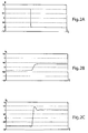
- FIGS 2a to 2F show the input and the output graphs of the system of Figure 1.
- Figure 2A shows a step input U as applied to the two sub-systems S1, S2.
- Figure 2B shows the output signal Y 1 of sub-system S1
- Figure 2C shows the output Y 2 of sub-system S2.
- figure 2D shows a step input U as applied to two servo mechanisms S1, S2 of a single SIMO system.
- Figures 2E and 2F show the respective outputs Y 1 , Y 2 .
- Figure 2E shows an output signal Y 1 of sub-system S1 which illustrates a variation occurring in the gain of the transfer function.
- Figure 2F shows an output signal Y 2 of sub-system S2 which illustrates that a sinusoidal noise signal appears in the output signal.
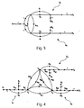
- FIG. 3 shows a diagram of a system having one input U and two outputs Y 1 and Y 2 , realised according a methodology of the prior art (Invariance of Penalities).
- N is a high number
- N(N-1) represents a very high number of connections and this entails the realisation of complex circuits and devices, the more so when the distance between the servo mechanisms to be controlled is increased.
- control systems according to this invention when systems having two servo mechanisms are involved, entails a complexity grade similar to the prior art, even if in such case the number of the necessary connections is increased.
- Figure 4 shows a general diagram of a system realised according to the prior art (Invariance of Penalities) comprising three sub-systems S1, S2, S3 corresponding, by way of exemplification, to three different servo mechanisms.
- [ A + F ] ⁇ 1 adj [ A + F ] ⁇ 3 .
- ⁇ 3
- F 1 F 2 + F 3 F 1 + F 3 F 2 + F 1 F 2 F 3 ⁇ ( a 13 a 21 a 32 + 1 + 1 + a 23 a 12 a 31 ) .
- ⁇ Y 1 ⁇ 3 ( Z 1 G 11 H 1 + Z 2 G 21 H 1 + Z 3 G 31 H 1 )
- Y 2 ⁇ 3 ( Z 1 G 11 H 2 + Z 2 G 21 H 2 + Z 3 G 31 H 2 )
- Y 3 ⁇ 3 ( Z 1 G 11 H 3 + Z 2 G 21 H 3 + Z 3 G 31 H 3 )
- noise signals D 1 , D 2 , D 3 has been assumed on the outputs of the sub-systems S1, S2, S3.
- Variable C is obtained by co-operation of all variables E i each provided with its own sign.
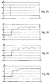
- Figures 7A to 7D illustrate graphs relating to the input U and the outputs Y 1 , Y 2 and Y 3 of the system of Figure 6, when a noise signal applied to the system S2 and a parametric variation applied to system S3 are present.
- N(N-1) the necessary number of connections is N(N-1), equal to the number of signals to be transmitted.
- the return signal from the auxiliary node Nc to the error nodes is the same for all of the three error nodes and this results of course into a higher realisation simplicity for the system.
Landscapes
- Engineering & Computer Science (AREA)
- Physics & Mathematics (AREA)
- General Physics & Mathematics (AREA)
- Automation & Control Theory (AREA)
- Robotics (AREA)
- Mechanical Engineering (AREA)
- Feedback Control In General (AREA)
- Control By Computers (AREA)
- Selective Calling Equipment (AREA)
- Control Of Multiple Motors (AREA)
Abstract
Description
- This invention relates to a single-input multi-output control system, particularly useful to obtain an equal distribution of the noise effects and of parametric variations among the outputs.
- In designing machines, often the need arises to obtain spatially co-ordinated movements of different points of the structure.
- Some examples of machines of this type are the mirrors of solar furnaces, the antennas of radio telescopes, the co-operating arms of a robot, the wheels of an electric vehicle, the trolleys for moving big rigid or flexible structures, the vibrating plates with six freedom grades, the ends of the legs of a walking vehicle, and so on.
- All systems of this kind are provided with two or more servo mechanisms that, when they receive identical input commands, should furnish outputs in constant ratio with one another, regardless of the noise signals acting on their input and/or of any possible parametric variations.
- A first well known solution to this problem provides for realising rigid mechanical connections between different points of the structure to be controlled, so as to constrain them in order to have the same behaviour in any case.
- However, such a solution is not always exploitable due to obvious reasons, because it may well happen that the servo mechanisms to be controlled are largely spaced apart from one another, so that it would not be possible to realise an absolutely rigid mechanical connection therebetween.
- A second well known solution, a very largely adopted solution, provides for realising servo mechanisms having high performance components, so as to reduce the sensitivity of the outputs of the concerned control systems in respect of the noise and of the parametric variations.
- However, a solution of this kind has the noticeable disadvantage that it is rather expensive and additionally it does not guarantee that anyway all of the outputs have the same behaviour, regardless of the various noise signals and of the different parametric variations that may affect the behaviour of the individual control systems.
- A control methodology (Invariance of Penalities) for systems of this kind is further known, which is based upon a mutual interconnection of the individual control systems of the individual servo mechanisms , in correspondence to the related error nodes.
- Petternella et al., in "Single Master-Multiple Slaves Manipulator with Penalty Invariance", R.Report, March 1976 (1976-03), pages 265-272, XP001134973, Italy, describe the application of the Penalty Invariance property to a single master-multiple slaves control system.
- Such a methodology allows obtaining a substantial identity of all outputs of the system (apart from the weights allotted to the coefficients of the feedback chains), but however it has the drawback that it requires anyway the realisation of complex circuits and devices, the more so when the number of servo mechanisms is increased and when the material distance between the concerned servo mechanisms is large.
- Furthermore, the systems of this kind are such that all of the servo mechanisms receive an identical input signal.
- It is an object of this invention to suggest a solution to the above mentioned problems based upon a single-input multi-output control system comprising two or more control sub-systems, each of said two or more control sub-systems having a corresponding error node and an output coincident with one of said multiple outputs, characterised in that said control systems comprises an auxiliary node, adapted to bi-directionally connect said error nodes with one another, the arrangement being such that, when noise signals and/or parametric variations are present, an equal distribution of said noise signals and/or parametric variations among said multiple outputs is obtained.
- The main advantage of a control system according to this invention derives from the fact that it allows to equally distribute the effects of the noise and/or of the parametric variations possibly affecting the individual control systems among the outputs of the controlled system.
- A second advantage derives from the fact that a system realised according to this invention does not include any mechanical connection between the points of the structure to be controlled and it furthermore makes it possible to avoid any wired cable electric connection between the individual mechanisms.
- A third advantage of the control system according to this invention derives from the fact that all of the servo mechanisms included therein are supplied with a single input , applied to any one of said servo mechanisms. This noticeably simplifies the material realisation of the whole system, because it avoid any need to supply identical inputs to all utilised servo mechanisms.
- A fourth advantage of the system according to this invention derives from the fact that it can be effectively obtained by utilising servo mechanisms realised with low cost and low performance control components and devices, without any functionality prejudice from the output identity view point.
- Further advantages, characteristics and modes of use of this invention will be evident from the following detailed description of its preferred embodiments shown by way of illustration and not by way of limitation, with reference to enclosed drawings, wherein:
- Figure 1 is a diagram of a system comprising two servo mechanisms realised according to a first methodology of prior and usual art,
- Figures 2A to 2F are graphs relating to the input and to the outputs of the system of Figure 1,
- Figure 3 is a diagram of a system comprising two servo mechanisms realised according to a second methodology of prior art,
- Figure 4 is a broad diagram of a system comprising three servo mechanisms,
- Figure 5 is a diagram of the system of Figure 4 in a particular case,
- Figure 6 is a diagram of a control system according to this invention comprising three servo mechanisms,
- Figures 7A to 7D are graphs relating to the input and to the outputs of the system of Figure 6, and
- Figure 8 is a broad diagram of a system according to this invention comprising N servo mechanisms.
- By referring firstly to Figure 1, it shows a diagram of a system comprising two servo mechanisms and including two control sub-systems S1, S2 realised according to methodologies of the prior art.
- For a system of this kind to be a system of SIMO (Single Input Multiple Output) type, namely a system having a single input and multiple outputs, it is necessary that U1 = U2 = U.
- In this case, the outputs of the system can be written as follows:
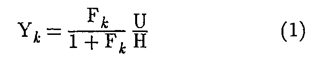
where Fk = HGk is the closed loop transfer function of the k-th system. - Consequently, the functions by which the sensitivity of output Yk with respect to the transfer function Gk can be expressed as follows:

and the outputs Ykh relating to a noise signal Dn acting on the output of the system are as follows:
- In all systems of this kind, even if the closed loop transfer functions Gk appear to be identical with respect to one another, if it is desired to obtain Y1 = Y2 under any conditions, it is necessary to realise sophisticated, very expensive and high performance servo mechanisms, even if they are not able to guarantee the obtainment of the desired result.
- Subsequent Figures 2a to 2F show the input and the output graphs of the system of Figure 1.
- In particular, Figure 2A shows a step input U as applied to the two sub-systems S1, S2.
- Figure 2B shows the output signal Y1 of sub-system S1, while Figure 2C shows the output Y2 of sub-system S2.
- In similar way, figure 2D shows a step input U as applied to two servo mechanisms S1, S2 of a single SIMO system.
- Figures 2E and 2F show the respective outputs Y1, Y2. Figure 2E shows an output signal Y1 of sub-system S1 which illustrates a variation occurring in the gain of the transfer function. Figure 2F shows an output signal Y2 of sub-system S2 which illustrates that a sinusoidal noise signal appears in the output signal.
- Subsequent Figure 3 shows a diagram of a system having one input U and two outputs Y1 and Y2 , realised according a methodology of the prior art (Invariance of Penalities).
- By setting the gain parameters a12 = a21 = -1, it can be easily calculated

where
- It can be easily understood from equation (4) that the two outputs resulting from the input signal U and from the noise signals D1 and D2 are identical with respect to one another, regardless of the performances of the individual servo mechanisms.
- Furthermore, it can be easily derived from equation (4) that

which evidences that the performances relating to the two outputs are also identical to one another also in respect of the parametric variations occurring in the transfer functions. - As far as the meaning of Φ2 is concerned, only the connection between input U and the i-th output should be considered, for the sake of simplicity:

- When the above expression is compared to the output of a complementary system written in the following form

it can be noted that the sum (1/F1 + 1/F2) replaces theterm 1/F and the closed loop transfer function Φ2 of the system according to this invention is obtained by parallel combination F1∥F2 of the closed loop transfer functions of the concerned two sub-systems. - However, it is necessary to underline that the expression of Y1 is true only if a12*a21 = 1.
- Anyway, often it practically occurs that a12*a21 = 1 + ε with ε equal to a very small numerical amount.
- Should ε be > 0, it would be easy to ascertain that radicals having a positive real part are present in the transfer function Φ2 with consequent system instability.
- On the contrary side, should ε be <0, it would be possible to utilise the Yi expression without substantial consequences to the performances of the comprehensive transfer function Φ2.
- The up to now described methodology (Invariance of Penalities) can also be applied to the realisation of SIMO type systems having more than two servo mechanisms, with results similar to the previous ones and derivable from an extension of the same.
- However, the exploitation of such methodology in respect of a system having N servo mechanisms entails the realisation of N(N-1) connections among the N servo mechanisms themselves.
- It is apparent that, if N is a high number, then also N(N-1) represents a very high number of connections and this entails the realisation of complex circuits and devices, the more so when the distance between the servo mechanisms to be controlled is increased.
- The embodiments of the control systems according to this invention, when systems having two servo mechanisms are involved, entails a complexity grade similar to the prior art, even if in such case the number of the necessary connections is increased.
- As it will be hereinafter detailedly described, th use of a system according to this embodiment appears to be anyway more convenient when the number of servo mechanisms is equal or greater than three.
- In a system of the third order, namely comprising three mechanisms, it is already more advantageous to utilise an embodiment according to this invention.
- In this case, in fact, even if the number of the necessary connections between the error nodes of the system is unchanged, the number of signals exchanged between the error nodes themselves is decreased. This will be apparent in the following description.
- Figure 4 shows a general diagram of a system realised according to the prior art (Invariance of Penalities) comprising three sub-systems S1, S2, S3 corresponding, by way of exemplification, to three different servo mechanisms.
- As regards such a system, it is obtained that

that, in matricial form, can be written as
- By setting G11·G12=G1, G21·G22=G2 and G31·G32=G3 it can be obtained :

that, in matricial form, can be written as
- By simple mathematical rearrangements, it can be obtained :


- In this case:

where
- By setting again all coefficients alk = akl = -1 for each l and k, it is obtained that

- The added matrix of equation (13) can be written as

- Furthermore:

- When equation (17) is substituted into equation (12), matrix Y of the systems outputs can be written as follows:

- By setting:

the system outputs due to inputs Zk assume the following form:
- Since

it can be obtained:
- The subsequent Figure 5 is a diagram of the system of Figure 4 in which, according to this invention, the following settings have been adopted : U1 = U, U2 = 0 and U3 = 0.
- Furthermore, the presence of noise signals D1, D2, D3 has been assumed on the outputs of the sub-systems S1, S2, S3.
- By selecting the gain coefficients aik according to equation (21) and by setting

and
into the general expression of F1, F2, F3, equation (22) furnishes, as far as the outputs due to the input:
- The three outputs due to the noise signals D1, D2, D3 can be derived from equation (22)

and
so as to obtain:
- By setting again H1 = H2 = H3 = H, it can be obtained:

- This equation evidences that, in a system according to this invention, having a single input U and a different noise signal Di acting upon each output, the effects of the input signal and of the three noise signals affect in identical manner the three outputs.
- By additionally considering the expression (19) relating to the comprehensive transfer function, it is easy to ascertain that the three outputs Y1, Y2 and Y3 remain equal to one another regardless of any parametric variations in G1 and/or G2 and/or G3.
- Again according to this invention, the system of Figure 5 can be advantageously realised according to the diagram illustrated in the following Figure 6.
- In this case, an auxillary node Nc has been introduced for co-operation among error nodes Nei.
- The variable associated to said auxiliary node Nc is furnished by:
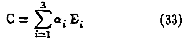
in which αi = ± 1, depending on the circumstances. - Variable C is obtained by co-operation of all variables Ei each provided with its own sign.
- By suitably selecting β = ± 1 and γ = ± 1 , equation (33) can easily be transformed as follows:

- When equation (33) is substituted into equation (34), it can be obtained:

which are expressions analogous to the expressions for the system related to the previous case. - By setting αi * βi = -γi, it can be obtained:

- It is possible to ascertain now that, depending on the selection of the coefficients, different signs can be obtained for the three outputs, even if the three outputs are equal or proportional to one another in respect of their absolute value.
- For instance, when it is necessary to obtain a k-th output with opposite sign with respect to the other two outputs, it will be necessary to change the sign of the connection coefficients between the k-th node and the auxiliary node.
- Figures 7A to 7D illustrate graphs relating to the input U and the outputs Y1, Y2 and Y3 of the system of Figure 6, when a noise signal applied to the system S2 and a parametric variation applied to system S3 are present.
- The above Figures evidence the result obtained by means of this invention, namely the possibility to obtain an equal distribution of any noise signals as well as of any parametric variations to all of the outputs of the system, without the need to make recourse to sophisticated and expensive devices.
- Lastly, the submitted observations and the up to now described mathematical arrangements can be extended to the case of a system comprising N servo mechanisms to be controlled.
- The mathematical arrangements relating to a case of this type will be now omitted for the sake of description simplicity, since they are well known to those skilled in the art.
- By referring to Figure 8, we can write:


- By selecting αi = 1 and βi = -1, it can be obtained:

in which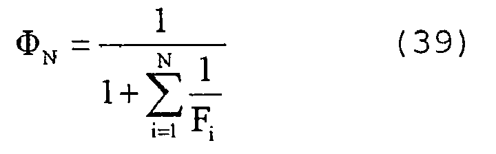
- It can be derived from the above that

- By referring to a system having a single input U applied to one of the servo mechanisms and N noise signals Di acting on the N outputs, it can be obtained:

- Also in this case, when it is desired to obtain outputs with different signs with respect to one another, it will be sufficient to correspondingly change the signs of the coefficients.
- By setting Hk = H for each k, it can be obtained:

- It should be further remarked that

in which, according to the symbology as up to now adopted:
- It can be easily ascertained that if, in steady state conditions, it is desired to obtain Ek = 0 when a step signal U is applied to the input, it is necessary that all transfer function Fk have at least a pole at the origin.
- It can be easily noted that, when a co-operation auxiliary node Nc is utilised, the necessary number of connections is 2N, where N is the number of sub-systems, while the number of signals to be transmitted is equal to N+1.
- In contrast, when direct connections are realised between the error nodes (prior art), the necessary number of connections is N(N-1), equal to the number of signals to be transmitted.
- This evidences the noticeable advantage deriving from the use of systems according to this invention, the more so when systems of an order equal to or higher than three are involved.
- In particular, the return signal from the auxiliary node Nc to the error nodes is the same for all of the three error nodes and this results of course into a higher realisation simplicity for the system.
- Let us consider, in fact, the case in which the signals are transmitted by means of wireless systems: it will be sufficient to transmit a single signal by means of a single transmitter from node C and all error nodes will receive it in the same way.
- Such an advantage becomes of course more relevant as the number of servo mechanisms and as their distances increase.
- Particular attention is to be dedicated to the realisation of the positive reactions equal to +1 on the error nodes.
- In fact, aiming at avoiding that the system become unstable, it is necessary that the signals coming from the auxiliary node as well as the corresponding reaction signals be available at the same time.
- Anyway, by selecting |βk| = γk = 1-ε, with ε sufficiently small, the possible unstability can be easily avoided without jeopardising the behaviour of the system in its whole.
- This invention has been up to now described according to its preferred embodiments by way of illustration, but not by way of limitation. It should be understood that other embodiments are possible all of which are to be considered as falling within the scope of this invention as defined by the attached claims.
Claims (9)
- A single-input multi-output control system comprising two or more control sub-systems, each of said two or more control sub-systems having a corresponding error node (Nei) and an output (Yi) coincident with one of said multiple outputs, said control system comprising an auxiliary node (Nc), adapted to bi-directionally connect said error nodes (Nei) with one another, the arrangement being such that, when noise signals and/or parametric variations are present, an equal distribution of said noise signals and/or parametric variations among said multiple outputs is obtained, said control system being characterised in that each one of said error nodes (Nei) is connected to itself via a loop auto-connection having a corresponding gain parameter.
- A system according to claim 1, wherein at least one of said gain parameters corresponding to said loop auto-connection has a value equal to 1.
- A system according to claim 1 or 2, wherein at least one of said gain parameters corresponding to said loop auto-connection has a value equal to -1.
- A system according to any one of the preceding claims, wherein said single input is applied as input to any one of said two or more control sub-systems.
- A system according to any one of the preceding claims, wherein a quantity (C) corresponds to said auxiliary node (Nc) and an error quantity (Ei) corresponds to each of said error nodes (Nei), said quantity (C) being the weighted algebraic sum of said quantities (Ei).
- A systems according to any one of the preceding claims, wherein a gain parameter corresponds to each of said connections between said auxiliary node (Nc) and one of said error nodes (Nei).
- A system according to claim 6, wherein at least one of said gain parameters has a value equal to 1.
- A system according to claim 6 or 7, wherein at least one of said gain parameters has a value equal to -1.
- A system according to any one of the preceding claims, wherein each of said two or more control sub-systems is of a feedback type, having a closed loop transfer function.
Applications Claiming Priority (3)
| Application Number | Priority Date | Filing Date | Title |
|---|---|---|---|
| IT2001RM000560A ITRM20010560A1 (en) | 2001-09-14 | 2001-09-14 | SINGLE INPUT AND MULTIPLE OUTPUT CONTROL SYSTEM. |
| ITRM20010560 | 2001-09-14 | ||
| PCT/IT2002/000585 WO2003025684A1 (en) | 2001-09-14 | 2002-09-13 | Single-input multi-output control system |
Publications (2)
| Publication Number | Publication Date |
|---|---|
| EP1425636A1 EP1425636A1 (en) | 2004-06-09 |
| EP1425636B1 true EP1425636B1 (en) | 2006-08-23 |
Family
ID=11455780
Family Applications (1)
| Application Number | Title | Priority Date | Filing Date |
|---|---|---|---|
| EP02798802A Expired - Lifetime EP1425636B1 (en) | 2001-09-14 | 2002-09-13 | Single-input multi-output control system |
Country Status (6)
| Country | Link |
|---|---|
| US (1) | US7133728B2 (en) |
| EP (1) | EP1425636B1 (en) |
| AT (1) | ATE337576T1 (en) |
| DE (1) | DE60214203D1 (en) |
| IT (1) | ITRM20010560A1 (en) |
| WO (1) | WO2003025684A1 (en) |
Families Citing this family (2)
| Publication number | Priority date | Publication date | Assignee | Title |
|---|---|---|---|---|
| SE540763C2 (en) * | 2017-03-31 | 2018-11-06 | Scania Cv Ab | A method in a control system and a control system including means arranged for controlling at least two actuators |
| CN111399379B (en) * | 2020-03-18 | 2021-04-16 | 华南理工大学 | Self-adaptive vibration control method of flexible satellite system based on output limitation |
Family Cites Families (5)
| Publication number | Priority date | Publication date | Assignee | Title |
|---|---|---|---|---|
| EP0263799A3 (en) * | 1986-10-07 | 1990-03-28 | Giancarlo Caporali | An interactive video network between one master computer and a plurality of slave computers |
| US5783923A (en) | 1995-12-06 | 1998-07-21 | William L. Wise | Method and apparatus for multiple-input, multiple output feedback control of variable load systems |
| US6618628B1 (en) * | 2000-10-05 | 2003-09-09 | Karl A. Davlin | Distributed input/output control systems and methods |
| JP3912379B2 (en) * | 2001-06-22 | 2007-05-09 | オムロン株式会社 | Safety network system, safety slave and communication method |
| US6956463B2 (en) * | 2002-10-02 | 2005-10-18 | Carrier Corporation | Method and apparatus for providing both power and communication over two wires between multiple low voltage AC devices |
-
2001
- 2001-09-14 IT IT2001RM000560A patent/ITRM20010560A1/en unknown
-
2002
- 2002-09-13 EP EP02798802A patent/EP1425636B1/en not_active Expired - Lifetime
- 2002-09-13 WO PCT/IT2002/000585 patent/WO2003025684A1/en not_active Ceased
- 2002-09-13 AT AT02798802T patent/ATE337576T1/en not_active IP Right Cessation
- 2002-09-13 US US10/487,098 patent/US7133728B2/en not_active Expired - Fee Related
- 2002-09-13 DE DE60214203T patent/DE60214203D1/en not_active Expired - Fee Related
Also Published As
| Publication number | Publication date |
|---|---|
| ITRM20010560A0 (en) | 2001-09-14 |
| US7133728B2 (en) | 2006-11-07 |
| US20040254657A1 (en) | 2004-12-16 |
| ITRM20010560A1 (en) | 2003-03-14 |
| WO2003025684A1 (en) | 2003-03-27 |
| ATE337576T1 (en) | 2006-09-15 |
| EP1425636A1 (en) | 2004-06-09 |
| DE60214203D1 (en) | 2006-10-05 |
Similar Documents
| Publication | Publication Date | Title |
|---|---|---|
| Semsar-Kazerooni et al. | Optimal consensus seeking in a network of multiagent systems: An LMI approach | |
| Wolovich | Skew prime polynomial matrices | |
| Schuler et al. | Decentralized state feedback control for interconnected systems with application to power systems | |
| Zhivoglyadov et al. | Networked control design for linear systems | |
| Date et al. | A parametrization approach to optimal H2 and H∞ decentralized control problems | |
| Nguyen et al. | An intelligent parameter determination approach in iterative learning control | |
| Popov et al. | Robust stability of a multi-agent system under arbitrary and time-varying communication topologies and communication delays | |
| Ao et al. | Adaptive leaderless consensus control of a class of strict feedback nonlinear systems with guaranteed transient performance under actuator faults | |
| US7133728B2 (en) | Single-input multi-output control system | |
| Oliveira et al. | Robust controllers enhanced with design and implementation processes | |
| Cherukuri et al. | Distributed algorithms for convex network optimization under non-sparse equality constraints | |
| Ali et al. | Synchronization of stochastic complex dynamical networks with mixed time-varying coupling delays | |
| Marinescu et al. | Robust state-predictive control with separation property: A reduced-state design for control systems with non-equal time delays | |
| Fagnani et al. | On multi-vehicle rendezvous under quantized communication | |
| Azimi et al. | Robust decentralised state feedback control design for large-scale networked control system | |
| Semsar-Kazerooni et al. | An LMI approach to optimal consensus seeking in multi-agent systems | |
| Krokavec et al. | Unknown-input observers for Metzlerian linear positive systems | |
| Johansson et al. | On quantization and communication topologies in multi-vehicle rendezvous | |
| Gawronski et al. | Frequency Weighting for the H and H Control Design of Flexible Structures | |
| JPH04302302A (en) | Two degree of free controller | |
| Shepit et al. | Sliding-mode control design for a complex valued sliding manifold | |
| Tong et al. | Design and simulation of an adaptive networked tracking control system | |
| Kernbach et al. | Towards self-adaptation of robot organisms with a high developmental plasticity | |
| Wan et al. | Data-driven model-free adaptive control for platooning systems with dual-channel event-triggered mechanism | |
| Lan et al. | Containment-Formation Control for Second-Order Nonlinear Multi-Agent Systems via Event-Triggering |
Legal Events
| Date | Code | Title | Description |
|---|---|---|---|
| PUAI | Public reference made under article 153(3) epc to a published international application that has entered the european phase |
Free format text: ORIGINAL CODE: 0009012 |
|
| 17P | Request for examination filed |
Effective date: 20040302 |
|
| AK | Designated contracting states |
Kind code of ref document: A1 Designated state(s): AT BE BG CH CY CZ DE DK EE ES FI FR GB GR IE IT LI LU MC NL PT SE SK TR |
|
| AX | Request for extension of the european patent |
Extension state: AL LT LV MK RO SI |
|
| 17Q | First examination report despatched |
Effective date: 20050408 |
|
| GRAP | Despatch of communication of intention to grant a patent |
Free format text: ORIGINAL CODE: EPIDOSNIGR1 |
|
| GRAS | Grant fee paid |
Free format text: ORIGINAL CODE: EPIDOSNIGR3 |
|
| GRAA | (expected) grant |
Free format text: ORIGINAL CODE: 0009210 |
|
| AK | Designated contracting states |
Kind code of ref document: B1 Designated state(s): AT BE BG CH CY CZ DE DK EE ES FI FR GB GR IE IT LI LU MC NL PT SE SK TR |
|
| PG25 | Lapsed in a contracting state [announced via postgrant information from national office to epo] |
Ref country code: LI Free format text: LAPSE BECAUSE OF FAILURE TO SUBMIT A TRANSLATION OF THE DESCRIPTION OR TO PAY THE FEE WITHIN THE PRESCRIBED TIME-LIMIT Effective date: 20060823 Ref country code: CH Free format text: LAPSE BECAUSE OF FAILURE TO SUBMIT A TRANSLATION OF THE DESCRIPTION OR TO PAY THE FEE WITHIN THE PRESCRIBED TIME-LIMIT Effective date: 20060823 Ref country code: CZ Free format text: LAPSE BECAUSE OF FAILURE TO SUBMIT A TRANSLATION OF THE DESCRIPTION OR TO PAY THE FEE WITHIN THE PRESCRIBED TIME-LIMIT Effective date: 20060823 Ref country code: AT Free format text: LAPSE BECAUSE OF FAILURE TO SUBMIT A TRANSLATION OF THE DESCRIPTION OR TO PAY THE FEE WITHIN THE PRESCRIBED TIME-LIMIT Effective date: 20060823 Ref country code: NL Free format text: LAPSE BECAUSE OF FAILURE TO SUBMIT A TRANSLATION OF THE DESCRIPTION OR TO PAY THE FEE WITHIN THE PRESCRIBED TIME-LIMIT Effective date: 20060823 Ref country code: FI Free format text: LAPSE BECAUSE OF FAILURE TO SUBMIT A TRANSLATION OF THE DESCRIPTION OR TO PAY THE FEE WITHIN THE PRESCRIBED TIME-LIMIT Effective date: 20060823 Ref country code: BE Free format text: LAPSE BECAUSE OF FAILURE TO SUBMIT A TRANSLATION OF THE DESCRIPTION OR TO PAY THE FEE WITHIN THE PRESCRIBED TIME-LIMIT Effective date: 20060823 Ref country code: SK Free format text: LAPSE BECAUSE OF FAILURE TO SUBMIT A TRANSLATION OF THE DESCRIPTION OR TO PAY THE FEE WITHIN THE PRESCRIBED TIME-LIMIT Effective date: 20060823 |
|
| REG | Reference to a national code |
Ref country code: GB Ref legal event code: FG4D |
|
| PG25 | Lapsed in a contracting state [announced via postgrant information from national office to epo] |
Ref country code: IE Free format text: LAPSE BECAUSE OF NON-PAYMENT OF DUE FEES Effective date: 20060913 |
|
| REG | Reference to a national code |
Ref country code: CH Ref legal event code: EP |
|
| REG | Reference to a national code |
Ref country code: IE Ref legal event code: FG4D |
|
| PG25 | Lapsed in a contracting state [announced via postgrant information from national office to epo] |
Ref country code: MC Free format text: LAPSE BECAUSE OF NON-PAYMENT OF DUE FEES Effective date: 20060930 |
|
| REF | Corresponds to: |
Ref document number: 60214203 Country of ref document: DE Date of ref document: 20061005 Kind code of ref document: P |
|
| PG25 | Lapsed in a contracting state [announced via postgrant information from national office to epo] |
Ref country code: BG Free format text: LAPSE BECAUSE OF FAILURE TO SUBMIT A TRANSLATION OF THE DESCRIPTION OR TO PAY THE FEE WITHIN THE PRESCRIBED TIME-LIMIT Effective date: 20061123 Ref country code: DK Free format text: LAPSE BECAUSE OF FAILURE TO SUBMIT A TRANSLATION OF THE DESCRIPTION OR TO PAY THE FEE WITHIN THE PRESCRIBED TIME-LIMIT Effective date: 20061123 Ref country code: SE Free format text: LAPSE BECAUSE OF FAILURE TO SUBMIT A TRANSLATION OF THE DESCRIPTION OR TO PAY THE FEE WITHIN THE PRESCRIBED TIME-LIMIT Effective date: 20061123 |
|
| PG25 | Lapsed in a contracting state [announced via postgrant information from national office to epo] |
Ref country code: ES Free format text: LAPSE BECAUSE OF FAILURE TO SUBMIT A TRANSLATION OF THE DESCRIPTION OR TO PAY THE FEE WITHIN THE PRESCRIBED TIME-LIMIT Effective date: 20061204 |
|
| PG25 | Lapsed in a contracting state [announced via postgrant information from national office to epo] |
Ref country code: PT Free format text: LAPSE BECAUSE OF FAILURE TO SUBMIT A TRANSLATION OF THE DESCRIPTION OR TO PAY THE FEE WITHIN THE PRESCRIBED TIME-LIMIT Effective date: 20070125 |
|
| NLV1 | Nl: lapsed or annulled due to failure to fulfill the requirements of art. 29p and 29m of the patents act | ||
| REG | Reference to a national code |
Ref country code: CH Ref legal event code: PL |
|
| PG25 | Lapsed in a contracting state [announced via postgrant information from national office to epo] |
Ref country code: DE Free format text: LAPSE BECAUSE OF NON-PAYMENT OF DUE FEES Effective date: 20070403 |
|
| EN | Fr: translation not filed | ||
| PLBE | No opposition filed within time limit |
Free format text: ORIGINAL CODE: 0009261 |
|
| STAA | Information on the status of an ep patent application or granted ep patent |
Free format text: STATUS: NO OPPOSITION FILED WITHIN TIME LIMIT |
|
| GBPC | Gb: european patent ceased through non-payment of renewal fee |
Effective date: 20061123 |
|
| 26N | No opposition filed |
Effective date: 20070524 |
|
| PG25 | Lapsed in a contracting state [announced via postgrant information from national office to epo] |
Ref country code: GB Free format text: LAPSE BECAUSE OF NON-PAYMENT OF DUE FEES Effective date: 20061123 |
|
| PG25 | Lapsed in a contracting state [announced via postgrant information from national office to epo] |
Ref country code: FR Free format text: LAPSE BECAUSE OF FAILURE TO SUBMIT A TRANSLATION OF THE DESCRIPTION OR TO PAY THE FEE WITHIN THE PRESCRIBED TIME-LIMIT Effective date: 20070511 Ref country code: GR Free format text: LAPSE BECAUSE OF FAILURE TO SUBMIT A TRANSLATION OF THE DESCRIPTION OR TO PAY THE FEE WITHIN THE PRESCRIBED TIME-LIMIT Effective date: 20061124 |
|
| PG25 | Lapsed in a contracting state [announced via postgrant information from national office to epo] |
Ref country code: EE Free format text: LAPSE BECAUSE OF FAILURE TO SUBMIT A TRANSLATION OF THE DESCRIPTION OR TO PAY THE FEE WITHIN THE PRESCRIBED TIME-LIMIT Effective date: 20060823 |
|
| PG25 | Lapsed in a contracting state [announced via postgrant information from national office to epo] |
Ref country code: TR Free format text: LAPSE BECAUSE OF FAILURE TO SUBMIT A TRANSLATION OF THE DESCRIPTION OR TO PAY THE FEE WITHIN THE PRESCRIBED TIME-LIMIT Effective date: 20060823 Ref country code: LU Free format text: LAPSE BECAUSE OF NON-PAYMENT OF DUE FEES Effective date: 20060913 |
|
| PG25 | Lapsed in a contracting state [announced via postgrant information from national office to epo] |
Ref country code: CY Free format text: LAPSE BECAUSE OF FAILURE TO SUBMIT A TRANSLATION OF THE DESCRIPTION OR TO PAY THE FEE WITHIN THE PRESCRIBED TIME-LIMIT Effective date: 20060823 Ref country code: FR Free format text: LAPSE BECAUSE OF FAILURE TO SUBMIT A TRANSLATION OF THE DESCRIPTION OR TO PAY THE FEE WITHIN THE PRESCRIBED TIME-LIMIT Effective date: 20060823 |
|
| PG25 | Lapsed in a contracting state [announced via postgrant information from national office to epo] |
Ref country code: IT Free format text: LAPSE BECAUSE OF NON-PAYMENT OF DUE FEES Effective date: 20090913 |
|
| PGRI | Patent reinstated in contracting state [announced from national office to epo] |
Ref country code: IT Effective date: 20110616 |
|
| PGFP | Annual fee paid to national office [announced via postgrant information from national office to epo] |
Ref country code: IT Payment date: 20121001 Year of fee payment: 11 |
|
| PG25 | Lapsed in a contracting state [announced via postgrant information from national office to epo] |
Ref country code: IT Free format text: LAPSE BECAUSE OF NON-PAYMENT OF DUE FEES Effective date: 20130913 |