EP1424876A2 - Microwave oven - Google Patents
Microwave oven Download PDFInfo
- Publication number
- EP1424876A2 EP1424876A2 EP03026536A EP03026536A EP1424876A2 EP 1424876 A2 EP1424876 A2 EP 1424876A2 EP 03026536 A EP03026536 A EP 03026536A EP 03026536 A EP03026536 A EP 03026536A EP 1424876 A2 EP1424876 A2 EP 1424876A2
- Authority
- EP
- European Patent Office
- Prior art keywords
- air
- duct
- microwave oven
- fan
- base plate
- Prior art date
- Legal status (The legal status is an assumption and is not a legal conclusion. Google has not performed a legal analysis and makes no representation as to the accuracy of the status listed.)
- Granted
Links
Images




Classifications
-
- F—MECHANICAL ENGINEERING; LIGHTING; HEATING; WEAPONS; BLASTING
- F24—HEATING; RANGES; VENTILATING
- F24C—DOMESTIC STOVES OR RANGES ; DETAILS OF DOMESTIC STOVES OR RANGES, OF GENERAL APPLICATION
- F24C7/00—Stoves or ranges heated by electric energy
- F24C7/02—Stoves or ranges heated by electric energy using microwaves
-
- H—ELECTRICITY
- H05—ELECTRIC TECHNIQUES NOT OTHERWISE PROVIDED FOR
- H05B—ELECTRIC HEATING; ELECTRIC LIGHT SOURCES NOT OTHERWISE PROVIDED FOR; CIRCUIT ARRANGEMENTS FOR ELECTRIC LIGHT SOURCES, IN GENERAL
- H05B6/00—Heating by electric, magnetic or electromagnetic fields
- H05B6/64—Heating using microwaves
- H05B6/642—Cooling of the microwave components and related air circulation systems
Definitions
- the present invention relates to microwave ovens, and more particularly, to a structure of a microwave oven, which can cool down various components of the microwave oven, smoothly.
- the microwave oven cooks food with heat from friction between molecules caused by disturbance of the molecular arrangement of the food made with a microwave (approx. 2,450MHz).
- the microwave oven may have one or more than one magnetrons.
- the microwave oven with one magnetron is used as domestic use where the microwave oven is not used frequently, and the microwave oven with more than one magnetrons is used as commercial use for convenience store and the like where the magnetron is used frequently.
- FIGS. 1 ⁇ 5 illustrate inside structures of related art microwave ovens each with two magnetrons schematically, referring to which the microwave oven will be described.
- the related art commercial microwave oven is provided with an outer case 11, a base plate 12, an inner case 13 of a cooking chamber, a front panel 14, a rear panel 15, and an outfit room.
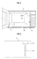
- the front panel 14 is mounted in a front part of the base plate 12, and, as shown in FIG. 2, the base plate 12 has a plurality of inflow holes 12a for drawing external air.
- the inner case 13 has a plurality of outflow holes 13a.
- the rear panel 15 is mounted in a rear part of the base plate 12, and, as shown in FIG. 3, has discharging holes 15a and 15b for discharging air.
- the one pair of transformers 16a and 16b are mounted on the base plate 12 side by side.
- the one pair of the magnetron 17a and 17b are mounted in an upper part and a lower part of the inner case 13, respectively.
- a microwave from the magnetrons 17a and 17b propagates to an upper space and a lower space of the inner case 13 through guide ducts (not shown).
- the fan 18a is mounted in a space between the transformers 16a and 16b, and the magnetrons 17a and 17b in the outer case 11, and connected to the fan motor 182b in a state protected with a fan housing 18c.
- the fan housing 18c has a suction side facing a lower space.
- the fan housing 18c is in communication with an air duct 19 for guiding air flow to the magnetrons 17a and 17b.
- An end of the air duct 19 is in communication with the discharging holes 15a and 15b in the rear panel 15.
- the fan 18a rotates as the fan motor 18b is driven, to draw external air.
- the external air is introduced into the microwave oven through the inflow holes 12a in the base plate 12, and cools the one pair of transformers 16a and 16b as the external air moves toward the fan 18a. Then, the external air cools the magnetrons 17a and 17b through the air duct 19 in communication with the fan housing 18c.
- the one pair of magnetrons in the related art microwave oven, mounted in a rear space of the magnetron, can not but increase the rear space of the microwave oven. Therefore, the inner case becomes smaller in comparison of a total size of the microwave oven. Moreover, the increase size of the microwave oven to require a more installation space can not but limit an installation space.
- the position of the fan mounted in a comer of one side of the outer case impedes the external air introduced through the base plate to cool the front transformer, smoothly. That is, since the front transformer is mounted in a blind area of air flow, cooling of the transformer has not been smooth.
- the fan motor in the related art microwave oven generates much heat when driven.
- the related art microwave oven is not provided with a separate structure for cooling the fan motor, overheat of the fan motor causes a poor performance.
- the present invention is directed to a microwave oven that substantially obviates one or more of the problems due to limitations and disadvantages of the related art.
- An object of the present invention is to provide a microwave oven in which cooling of various components are smooth.
- the microwave oven includes an outer case forming a top and sides of a cabinet, a base plate forming a bottom of the cabinet, a front panel and a rear panel mounted in a front part and a rear part of the base plate for forming a front surface and a rear surface respectively, an inner case forming a cooking chamber on the base plate, first and second transformer mounted at comers of one side of the base plate, a fan above the second transformer for drawing external air, a fan motor connected to the fan for providing a driving power to the fan, a fan housing for protecting the fan, an air duct between the first and second transformers, having one end in communication with the fan housing and the other end branched to first and second branch ducts, and first and second magnetrons on an outside surface of the inner case, the first and second magnetrons connected to the first and second branch ducts, respectively.
- the base plate includes a front part having a plurality of inflow holes
- the inner case includes a plurality of inlet holes for introduction of the air passed through the first and second branch ducts and the first and second magnetrons, and a plurality of outlet holes for discharging the air introduced into the inner case through the inlet holes.
- the outlet holes are connected to a plurality of discharging ducts for guiding flow of air discharged from the inner case.
- the rear panel has a plurality of first outlet holes connected to the discharging ducts for discharging air to an outside of the cabinet.
- the base plate is provided with a guide for uniform supply of external air introduced thereto through the inflow holes to the first and second transformers.
- the guide has a form of a square bar with one positioned between the inflow holes, and the other end positioned between the first and second transformers.
- the rear panel has a third outflow holes for discharging the air passed through the second transformer, and the air duct is mounted spaced a distance apart from an inside wall of the outer case.
- the first and second branch ducts of the air duct include sloped duct walls respectively such that each of the ducts becomes the narrower as it goes closer to a part connected to the first or second magnetron.
- the first branch duct is connected to a first duct for guiding air flow toward the fan motor, and the first magnetron is connected to the first duct.
- the rear panel has a second outflow hole for discharging the air cooled the fan motor through the first duct to an outside of the cabinet.
- the air duct includes a split guide between the first and second branch ducts for guiding the air introduced thereto through the fan.
- the split guide is formed by bending an inside wall of the air duct.
- the first branch duct is connected to a second duct for guiding flow of air to the rear panel, and the first magnetron is mounted in the second duct.
- the rear panel includes a second outflow hole connected to the second duct for discharging the air introduced thereto to an outside of the cabinet.
- the second duct includes a first communication hole formed therein for supplying air for cooling the fan motor.
- the second branch duct is connected to a third duct for guiding flow of air to the rear panel, and the second magnetron is in the third duct.
- the rear panel includes a third outflow hole for discharging the air introduced thereto to an outside of the cabinet, and the third duct includes a second communication hole for guiding air flow to the fan motor.
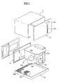
- the first embodiment microwave oven of the present invention includes an outer case 110, a base plate 120, a front panel 140, and a rear panel 150 to form a cabinet of the microwave oven.
- the outer case 110 forms side surfaces and a top surface
- the base plate 120 forms a bottom of the cabinet.
- the front panel 140, and the rear panel 150 are mounted in a front part and the rear part of the base plate 120, to form a front face and a rear face of the cabinet.
- the inner case 130 is used as a cooking chamber, and has transformers, an air duct 190, and various electronic components, such as magnetrons, fitted at sides thereof.
- the transformer includes first and second transformers 161 and 162 mounted at comers of one side of the base plate 120. As shown in FIG. 9, there is a fan 181 above the second transformer 162 for drawing external air. The fan 181 is protected by the fan housing 183, and coupled with the fan motor 182.
- the air duct 190 is fitted between the first and second transformers 161 and 162, and has one end in communication with the fan housing 183, and the other end branched into first and second branch ducts 190a, and 190b.
- the magnetron is mounted on an outside surface of the inner case 130, and includes first and second magnetrons 171 and 172 connected to the branch ducts 190a and 190b.
- the first and second magnetrons 171 and 172 are cooled by the air introduced into the first and second branch ducts 190a and 190b.
- the base plate 120 has a plurality of inflow holes 121 in a front surface thereof.
- the inflow holes 121 serves as ducts of external air introduced into the cabinet by the fan 181.
- the inner case 130 has a plurality of inlet holes 131a and 131b for introduction of the air having cooled the magnetrons 171 and 172.
- the outlet holes 132a and 132b discharge the air introduced into the inner case 130 through the inlet holes 131a and 131b.
- discharge air ducts 134 and 135 fitted to an outside surface of the inner case 130 having the outlet holes 132a and 132b formed therein.
- the discharge air ducts 134 and 135 guide air discharged through the outlet holes 132a and 132b, respectively.
- the first discharge air duct 134 is connected to the outlet holes 132a on the top surface of the inner case 130, and the second discharge air duct 135 is connected to the outlet holes 132a in a bottom thereof.
- the rear panel 150 has a plurality of first outflow holes 151a and 151b.
- the first outflow holes 151a and 151b are connected to the discharge air ducts 134 and 135 for discharging air to an outside of the cabinet, respectively. Therefore, positions of the first outflow holes 151a and 151b are dependent on end positions of the discharge air ducts, respectively.
- the first outflow holes 151a and 151b are in an upper part and a lower part of one side part of he rear panel 150.
- the rear panel 150 also has a third outflow hole 153 for discharging the air passed through the second transformer 162.
- the third outflow hole 153 discharges the portion of air that is not introduced into the air duct 190 of the air introduced through the inflow holes 121 and cooled the second transformer 162. According to this, air flow in the microwave oven becomes smooth, to increase a flow rate of inflow/outflow air, to improve a cooling efficiency of the transformers 161 and 162.
- the base plate 120 has a guide 122 for supplying the external air introduced through the inflow holes 121 both to the first and second transformers 161 and 162 at the same time.
- the guide 122 in a form of a bar, is provided between the first and second transformers 161 and 162.
- the guide 122 has one end positioned between the inflow holes 121, and the other end positioned between the first, and second transformers 161 and 162. Accordingly, the external air is provided to the first and second transformers 161 and 162 at the same time by the guide 122, and cools the first and second transformers 161, and 162, uniformly.
- the guide 122 may be formed such that the external air passes through the first and second transformers 161 and 162 in succession.
- uniform cooling of the transformers 161 and 162 is more favorable for improving performance of the transformers 161 and 162. Therefore, in the embodiments of the present invention, the guide 122 is formed such that an end of the guide 122 is directed a point substantially in the middle of the transformers 161 and 162.
- the air duct 190 is spaced a distance from an inside wall of the outside case 110. Therefore, as there is a gap between the air duct 190 and the outside case 110, flow of an inside air becomes smooth.
- the first and second branch ducts 190a and 190b of the air ducts 190 has a sloped duct walls such that the duct becomes the narrower as it goes closer to a part connected to the first and second magnetrons 161 and 162. This structure increases a flow speed of the air passing through the first and second branch ducts 190a and 190b, to enable smooth outflow and inflow of the air.
- the air duct 190 has a split guide 190c formed between the first and second branch ducts 190a and 190b.
- the split guide 190c guides the air introduced thereto through the fan 181 to the first and second branch ducts 190a and 190b.
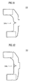
- the split guide 190c may be formed by bending an inside wall of the air duct 190, or as a separate unit projected from the inside wall of the air duct 190 as shown in FIG. 12.
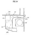
- the first branch duct 190a is connected to a first duct 191 for guiding air to the fan motor 182.
- the first magnetron 171 is connected to the first duct 191. Therefore, the air introduced into the first branch duct 190a cools the fan motor 182 and the first magnetron 171 following the first duct 191. It is preferable that the first duct 191 is formed as a unit with the air duct 190.
- the first duct 191 a part of the air duct 190 at a position of the fan motor 182 may be opened, for guiding a portion of the air from the air duct 190 to the fan motor 182, for cooling the fan motor 182.
- a second outflow hole 152 is formed in the rear panel 150, additionally.
- the fan 181 Upon putting the microwave oven into operation, the fan 181 is driven by the fan motor 182 to draw external air. In the instance, the external air is introduced into the cabinet through the inflow holes 121 in the base plate 120.
- the external air is guided to the first transformer 161 and the second transformer 162 at the same time by the guide 122 on the base plate 120, to cool the transformers 161 and 162, respectively.
- the air flowing through the air duct 190 is split into the first and second branch ducts 190a and 190b by the split guide 190c.
- the air introduced into the first branch duct 190a moves along the first duct 191 and passes through the first magnetron 171.
- a portion of the air passed through the first magnetron 171 is introduced into the cooking chamber in the inner case 130 through the inlet holes 131a. Rest of the air moves along the first duct 191 to a space the fan motor 182 is positioned therein, and cools the fan motor 182. Then, the air that cooled the fan motor 182 is discharged to rear of the microwave oven through the second outflow holes 152 in the rear panel 150.
- the air introduced into the second branch duct 190b is introduced into the inner case 130 through the inlet holes 131b via the second magnetron 172.
- the air introduced into the cooking chamber circulates inside of the cooking chamber, and introduced into the first and second discharge ducts 134 and 135 through the outlet holes 132a and 132b, respectively. Then, the air moves along the discharge ducts 134 and 135, and discharged to rear of the microwave oven through the first outflow holes 151a and 151b.
- the second embodiment of the present invention suggests a second duct 193 connected to the first branch duct 190a for guiding air flow to the rear panel 150.
- the second duct 193 is connected to the second outflow hole 152 in the rear panel 150 directly, and the first magnetron 171 is installed in the second duct 193.
- the second duct 193 has a first communication hole 193a for cooling the fan motor 182.
- the first communication hole 193a guides a portion of the air flowing through the second duct 193 to the fan motor 182 to cool the fan motor 182.
- a portion of the air introduced into the second duct 193 is introduced into the inner case 130 through the inlet holes 131a, and rest of the air is discharged to an outside of the cabinet through the second outflow hole 152 via the second duct 193.
- a portion of the air flowing toward the second outflow hole 152 along the second duct 193 is introduced into a space of the fan motor 182 through the first communication hole 193a, and cools the fan motor 182.
- the second duct 193 discharges the air introduced into the cabinet by the fan 181 as quick as possible to an outside of the cabinet. Therefore, by increasing a flow rate of the air introduced into the second duct 193, an overall cooling efficiency of the microwave oven can be improved.
- the third embodiment of the present invention suggests a third duct 194 connected to the second branch duct 190b for guiding air flow toward the rear panel 150.
- the third duct 194 is connected to the third outflow hole 153 in the rear panel 150, and the second magnetron 172 is mounted inside of the third duct 194.
- the third duct 194 also has a second communication hole 194a for cooling the fan motor 182, too. Therefore, if the third duct 194 and the second duct 193 are fitted together, not only the cooling efficiency of the fan motor 182 can be improved, but also an internal air flow can be made smoother. In this instance, the third duct 194 may, or may not be formed as a unit with the second duct 193.
- the structures of the foregoing embodiments may be applied to microwave ovens for stores which have two transformers and two magnetrons, or even to microwave ovens for domestic use having one of the magnetrons and the transformers removed therefrom.
- the microwave oven having one of the magnetrons and the transformers removed therefrom can be a domestic microwave oven. Therefore, by adjusting numbers of the magnetrons and the transformers mounted thereon, the microwave ovens of the present invention can be used as microwave ovens for stores or for homes.
- the microwave oven of the present invention has the following advantages.
- a front to rear length of the microwave oven can be reduced. According to this, a size of the cooking chamber can be enlarged, to provide a more useful structure.
- the structure of the present invention permits smooth cooling of the transformer in a part air flow thereto is poor in the related art by guiding air thereto.
- the smooth cooling of the fan motor can minimizes damage to the fan motor caused by overheating of the fan motor.
- the microwave oven of the present invention permits manufacturing of microwave ovens of different purposes of use with one production line.
- microwave oven for home and microwave oven for stores are different in the related art, different production lines are required for each of purposes of use of the microwave ovens.
- what is required for the microwave oven of the present invention is change of the numbers of magnetron and transformers, manufacturing of the microwave oven with only one production line is possible.
Landscapes
- Physics & Mathematics (AREA)
- Electromagnetism (AREA)
- Engineering & Computer Science (AREA)
- Chemical & Material Sciences (AREA)
- Combustion & Propulsion (AREA)
- Mechanical Engineering (AREA)
- General Engineering & Computer Science (AREA)
- Electric Ovens (AREA)
- Constitution Of High-Frequency Heating (AREA)
Abstract
Description
Claims (20)
- A microwave oven comprising:an outer case forming a top and sides of a cabinet;a base plate forming a bottom of the cabinet;a front panel and a rear panel mounted in a front part and a rear part of the base plate for forming a front surface and a rear surface, respectively;an inner case forming a cooking chamber on the base plate;first and second transformer mounted at comers of one side of the base plate;a fan above the second transformer for drawing external air;a fan motor connected to the fan for providing a driving power to the fan;a fan housing for protecting the fan;an air duct between the first and second transformers, having one end in communication with the fan housing and the other end branched to first and second branch ducts; andfirst and second magnetrons on an outside surface of the inner case, the first and second magnetrons connected to the first and second branch ducts, respectively.
- The microwave oven as claimed in claim 1, wherein the base plate includes a front part having a plurality of inflow holes.
- The microwave oven as claimed in claim 1, wherein the inner case includes;
a plurality of inlet holes for introduction of the air passed through the first and second branch ducts and the first and second magnetrons, and
a plurality of outlet holes for discharging the air introduced into the inner case through the inlet holes. - The microwave oven as claimed in claim 3, wherein the outlet holes are connected to a plurality of discharging ducts for guiding flow of air discharged from the inner case.
- The microwave oven as claimed in claim 4, wherein the rear panel has a plurality of first outlet holes connected to the discharging ducts for discharging air to an outside of the cabinet.
- The microwave oven as claimed in claim 2, wherein the base plate is provided with a guide for uniform supply of external air introduced thereto through the inflow holes to the first and second transformers.
- The microwave oven as claimed in claim 6, wherein the guide has a form of a square bar with one positioned between the inflow holes, and the other end positioned between the first and second transformers.
- The microwave oven as claimed in claim 1, wherein the rear panel has a third outflow holes for discharging the air passed through the second transformer.
- The microwave oven as claimed in claim 1, wherein the air duct is mounted spaced a distance apart from an inside wall of the outer case.
- The microwave oven as claimed in claim 9, wherein the first and second branch ducts of the air duct include sloped duct walls respectively such that each of the ducts becomes the narrower as it goes closer to a part connected to the first or second magnetron.
- The microwave oven as claimed in claim 10, wherein the first branch duct is connected to a first duct for guiding air flow toward the fan motor, and the first magnetron is connected to the first duct.
- The microwave oven as claimed in claim 10, wherein the rear panel has a second outflow hole for discharging the air cooled the fan motor through the first duct to an outside of the cabinet.
- The microwave oven as claimed in claim 1, wherein the air duct includes a split guide between the first and second branch ducts for guiding the air introduced thereto through the fan.
- The microwave oven as claimed in claim 13, wherein the split guide is formed by bending an inside wall of the air duct.
- The microwave oven as claimed in claim 10, wherein the first branch duct is connected to a second duct for guiding flow of air to the rear panel, and the first magnetron is mounted in the second duct.
- The microwave oven as claimed in claim 15, wherein the rear panel includes a second outflow hole connected to the second duct for discharging the air introduced thereto to an outside of the cabinet.
- The microwave oven as claimed in claim 16, wherein the second duct includes a first communication hole formed therein for supplying air for cooling the fan motor.
- The microwave oven as claimed in claim 10, wherein the second branch duct is connected to a third duct for guiding flow of air to the rear panel, and the second magnetron is in the third duct.
- The microwave oven as claimed in claim 18, wherein the rear panel includes a third-outflow hole for discharging the air introduced thereto to an outside of the cabinet.
- The microwave oven as claimed in claim 19, wherein the third duct includes a second communication hole for guiding air flow to the fan motor.
Applications Claiming Priority (2)
| Application Number | Priority Date | Filing Date | Title |
|---|---|---|---|
| KR2002072423 | 2002-11-20 | ||
| KR10-2002-0072423A KR100510655B1 (en) | 2002-11-20 | 2002-11-20 | microwave oven |
Publications (3)
| Publication Number | Publication Date |
|---|---|
| EP1424876A2 true EP1424876A2 (en) | 2004-06-02 |
| EP1424876A3 EP1424876A3 (en) | 2004-07-07 |
| EP1424876B1 EP1424876B1 (en) | 2007-01-17 |
Family
ID=32291805
Family Applications (1)
| Application Number | Title | Priority Date | Filing Date |
|---|---|---|---|
| EP03026536A Expired - Lifetime EP1424876B1 (en) | 2002-11-20 | 2003-11-18 | Microwave oven |
Country Status (6)
| Country | Link |
|---|---|
| US (1) | US6909079B2 (en) |
| EP (1) | EP1424876B1 (en) |
| KR (1) | KR100510655B1 (en) |
| AU (1) | AU2003262310B2 (en) |
| CA (1) | CA2450045C (en) |
| DE (1) | DE60311225T2 (en) |
Cited By (2)
| Publication number | Priority date | Publication date | Assignee | Title |
|---|---|---|---|---|
| CN101995041A (en) * | 2009-08-21 | 2011-03-30 | 乐金电子(天津)电器有限公司 | Wind scooper for microwave oven |
| CN103221747A (en) * | 2010-11-25 | 2013-07-24 | 大宇电子株式会社 | Microwave oven |
Families Citing this family (7)
| Publication number | Priority date | Publication date | Assignee | Title |
|---|---|---|---|---|
| US7235763B2 (en) * | 2004-04-08 | 2007-06-26 | Aga Foodservice Group | Cooking appliance including combination heating system |
| KR100603526B1 (en) * | 2004-10-26 | 2006-07-24 | 엘지전자 주식회사 | Cooling system for electric parts of microwave oven combined with hood |
| FR2885003B1 (en) * | 2005-04-22 | 2007-06-29 | Premark Feg Llc | MICROWAVE OVEN WITH COOLING AIR DUCT |
| US20090239460A1 (en) * | 2006-04-27 | 2009-09-24 | Wright Line, Llc | Assembly for Extracting Heat from a Housing for Electronic Equipment |
| WO2011028724A1 (en) * | 2009-09-01 | 2011-03-10 | Manitowoc Foodservice Companies, Llc. | Method and apparatus for venting a cooking device |
| JP2013096598A (en) * | 2011-10-28 | 2013-05-20 | Sharp Corp | Heating cooker |
| CN108731037A (en) * | 2018-04-04 | 2018-11-02 | 美的集团股份有限公司 | Micro-wave oven |
Family Cites Families (14)
| Publication number | Priority date | Publication date | Assignee | Title |
|---|---|---|---|---|
| US3654417A (en) | 1970-10-30 | 1972-04-04 | Litton Precision Prod Inc | Microwave oven including air flow system |
| US4184945A (en) * | 1978-06-12 | 1980-01-22 | Litton Systems, Inc. | Microwave wall oven air flow system |
| JPS55128393U (en) | 1979-03-06 | 1980-09-10 | ||
| US4786774A (en) | 1984-04-27 | 1988-11-22 | Sharp Kabushiki Kaisha | Combination compact microwave oven and ventilator system |
| JPS63127026A (en) * | 1986-11-17 | 1988-05-30 | Matsushita Electric Ind Co Ltd | Cooling device for high frequency heating equipment |
| JPH01225835A (en) * | 1988-03-04 | 1989-09-08 | Sanyo Electric Co Ltd | Cooker |
| DE8915020U1 (en) | 1989-12-21 | 1990-03-01 | Bosch-Siemens Hausgeraete Gmbh, 8000 Muenchen | Microwave household appliance |
| JPH05322186A (en) * | 1992-05-22 | 1993-12-07 | Sanyo Electric Co Ltd | Microwave oven |
| JP2740411B2 (en) * | 1992-05-25 | 1998-04-15 | 三洋電機株式会社 | microwave |
| KR960041905A (en) * | 1995-05-16 | 1996-12-19 | 구자홍 | Microwave Air Flow Structure |
| JPH1019269A (en) * | 1996-06-26 | 1998-01-23 | Toshiba Corp | microwave |
| KR100264122B1 (en) * | 1997-07-10 | 2000-08-16 | 윤종용 | Electric appliance chiller of microwave |
| KR100286171B1 (en) * | 1997-08-23 | 2001-05-02 | 윤종용 | Microwave |
| KR100369829B1 (en) | 1999-11-16 | 2003-01-29 | 삼성전자 주식회사 | Microwave oven |
-
2002
- 2002-11-20 KR KR10-2002-0072423A patent/KR100510655B1/en not_active Expired - Fee Related
-
2003
- 2003-11-17 AU AU2003262310A patent/AU2003262310B2/en not_active Ceased
- 2003-11-17 US US10/713,271 patent/US6909079B2/en not_active Expired - Fee Related
- 2003-11-18 DE DE60311225T patent/DE60311225T2/en not_active Expired - Lifetime
- 2003-11-18 CA CA002450045A patent/CA2450045C/en not_active Expired - Fee Related
- 2003-11-18 EP EP03026536A patent/EP1424876B1/en not_active Expired - Lifetime
Cited By (3)
| Publication number | Priority date | Publication date | Assignee | Title |
|---|---|---|---|---|
| CN101995041A (en) * | 2009-08-21 | 2011-03-30 | 乐金电子(天津)电器有限公司 | Wind scooper for microwave oven |
| CN103221747A (en) * | 2010-11-25 | 2013-07-24 | 大宇电子株式会社 | Microwave oven |
| EP2645004A4 (en) * | 2010-11-25 | 2014-11-19 | Dongbu Daewoo Electronics Corp | Microwave oven |
Also Published As
| Publication number | Publication date |
|---|---|
| EP1424876B1 (en) | 2007-01-17 |
| EP1424876A3 (en) | 2004-07-07 |
| CA2450045C (en) | 2007-03-20 |
| AU2003262310A1 (en) | 2004-06-10 |
| DE60311225T2 (en) | 2007-11-15 |
| KR20040043953A (en) | 2004-05-27 |
| DE60311225D1 (en) | 2007-03-08 |
| US6909079B2 (en) | 2005-06-21 |
| CA2450045A1 (en) | 2004-05-20 |
| AU2003262310B2 (en) | 2005-08-04 |
| KR100510655B1 (en) | 2005-08-30 |
| US20040094541A1 (en) | 2004-05-20 |
Similar Documents
| Publication | Publication Date | Title |
|---|---|---|
| US7856973B2 (en) | Cooking appliance | |
| CA2449536C (en) | Commercial microwave oven | |
| US6541746B2 (en) | Microwave oven with a convectional heating apparatus | |
| EP1424876B1 (en) | Microwave oven | |
| US6972398B2 (en) | Wall mounted type microwave oven | |
| JP2002221324A (en) | Cooling device for electric accessory part for combination hood and microwave oven | |
| EP1220575B1 (en) | Ventilation structure of microwave oven and lamp fitting structure therefor | |
| US6849840B2 (en) | Microwave oven with inverter and cooling assembly | |
| EP1665892B1 (en) | Microwave oven | |
| JP3458464B2 (en) | High frequency heating equipment | |
| CN100360852C (en) | Microwave oven | |
| KR100936154B1 (en) | Microwave | |
| EP1585369B1 (en) | Microwave oven with turntable | |
| KR100936153B1 (en) | Microwave | |
| KR200147433Y1 (en) | Rear plate structure of microwave oven | |
| KR200165206Y1 (en) | Structure for cooling microwave oven range | |
| KR100595261B1 (en) | Convection Microwave | |
| KR101388709B1 (en) | A fan-guide and microwave oven comprising the same | |
| KR20010057193A (en) | Built-in type microwave oven | |
| KR20000011342U (en) | Microwave | |
| JPS61263089A (en) | High frequency heater | |
| KR20090065059A (en) | Microwave | |
| KR20010109946A (en) | Built-in type microwave oven |
Legal Events
| Date | Code | Title | Description |
|---|---|---|---|
| PUAI | Public reference made under article 153(3) epc to a published international application that has entered the european phase |
Free format text: ORIGINAL CODE: 0009012 |
|
| PUAL | Search report despatched |
Free format text: ORIGINAL CODE: 0009013 |
|
| 17P | Request for examination filed |
Effective date: 20031118 |
|
| AK | Designated contracting states |
Kind code of ref document: A2 Designated state(s): AT BE BG CH CY CZ DE DK EE ES FI FR GB GR HU IE IT LI LU MC NL PT RO SE SI SK TR |
|
| AX | Request for extension of the european patent |
Extension state: AL LT LV MK |
|
| AK | Designated contracting states |
Kind code of ref document: A3 Designated state(s): AT BE BG CH CY CZ DE DK EE ES FI FR GB GR HU IE IT LI LU MC NL PT RO SE SI SK TR |
|
| AX | Request for extension of the european patent |
Extension state: AL LT LV MK |
|
| 17Q | First examination report despatched |
Effective date: 20050214 |
|
| AKX | Designation fees paid |
Designated state(s): DE FR GB IT |
|
| GRAP | Despatch of communication of intention to grant a patent |
Free format text: ORIGINAL CODE: EPIDOSNIGR1 |
|
| GRAS | Grant fee paid |
Free format text: ORIGINAL CODE: EPIDOSNIGR3 |
|
| GRAA | (expected) grant |
Free format text: ORIGINAL CODE: 0009210 |
|
| AK | Designated contracting states |
Kind code of ref document: B1 Designated state(s): DE FR GB IT |
|
| REG | Reference to a national code |
Ref country code: GB Ref legal event code: FG4D |
|
| REF | Corresponds to: |
Ref document number: 60311225 Country of ref document: DE Date of ref document: 20070308 Kind code of ref document: P |
|
| ET | Fr: translation filed | ||
| PLBE | No opposition filed within time limit |
Free format text: ORIGINAL CODE: 0009261 |
|
| STAA | Information on the status of an ep patent application or granted ep patent |
Free format text: STATUS: NO OPPOSITION FILED WITHIN TIME LIMIT |
|
| 26N | No opposition filed |
Effective date: 20071018 |
|
| PGFP | Annual fee paid to national office [announced via postgrant information from national office to epo] |
Ref country code: GB Payment date: 20131011 Year of fee payment: 11 Ref country code: DE Payment date: 20131015 Year of fee payment: 11 Ref country code: FR Payment date: 20131015 Year of fee payment: 11 |
|
| PGFP | Annual fee paid to national office [announced via postgrant information from national office to epo] |
Ref country code: IT Payment date: 20131118 Year of fee payment: 11 |
|
| REG | Reference to a national code |
Ref country code: DE Ref legal event code: R119 Ref document number: 60311225 Country of ref document: DE |
|
| GBPC | Gb: european patent ceased through non-payment of renewal fee |
Effective date: 20141118 |
|
| REG | Reference to a national code |
Ref country code: FR Ref legal event code: ST Effective date: 20150731 |
|
| PG25 | Lapsed in a contracting state [announced via postgrant information from national office to epo] |
Ref country code: DE Free format text: LAPSE BECAUSE OF NON-PAYMENT OF DUE FEES Effective date: 20150602 Ref country code: GB Free format text: LAPSE BECAUSE OF NON-PAYMENT OF DUE FEES Effective date: 20141118 |
|
| PG25 | Lapsed in a contracting state [announced via postgrant information from national office to epo] |
Ref country code: FR Free format text: LAPSE BECAUSE OF NON-PAYMENT OF DUE FEES Effective date: 20141201 |
|
| PG25 | Lapsed in a contracting state [announced via postgrant information from national office to epo] |
Ref country code: IT Free format text: LAPSE BECAUSE OF NON-PAYMENT OF DUE FEES Effective date: 20141118 |