EP1424785A2 - Spread spectrum communication device - Google Patents
Spread spectrum communication device Download PDFInfo
- Publication number
- EP1424785A2 EP1424785A2 EP03257367A EP03257367A EP1424785A2 EP 1424785 A2 EP1424785 A2 EP 1424785A2 EP 03257367 A EP03257367 A EP 03257367A EP 03257367 A EP03257367 A EP 03257367A EP 1424785 A2 EP1424785 A2 EP 1424785A2
- Authority
- EP
- European Patent Office
- Prior art keywords
- measurement
- period
- delay
- time
- spreading codes
- Prior art date
- Legal status (The legal status is an assumption and is not a legal conclusion. Google has not performed a legal analysis and makes no representation as to the accuracy of the status listed.)
- Withdrawn
Links
Images















Classifications
-
- H—ELECTRICITY
- H04—ELECTRIC COMMUNICATION TECHNIQUE
- H04B—TRANSMISSION
- H04B1/00—Details of transmission systems, not covered by a single one of groups H04B3/00 - H04B13/00; Details of transmission systems not characterised by the medium used for transmission
- H04B1/69—Spread spectrum techniques
- H04B1/707—Spread spectrum techniques using direct sequence modulation
- H04B1/7097—Interference-related aspects
- H04B1/711—Interference-related aspects the interference being multi-path interference
- H04B1/7113—Determination of path profile
-
- H—ELECTRICITY
- H04—ELECTRIC COMMUNICATION TECHNIQUE
- H04L—TRANSMISSION OF DIGITAL INFORMATION, e.g. TELEGRAPHIC COMMUNICATION
- H04L1/00—Arrangements for detecting or preventing errors in the information received
- H04L1/20—Arrangements for detecting or preventing errors in the information received using signal quality detector
-
- H—ELECTRICITY
- H04—ELECTRIC COMMUNICATION TECHNIQUE
- H04L—TRANSMISSION OF DIGITAL INFORMATION, e.g. TELEGRAPHIC COMMUNICATION
- H04L25/00—Baseband systems
- H04L25/02—Details ; arrangements for supplying electrical power along data transmission lines
- H04L25/0202—Channel estimation
- H04L25/0212—Channel estimation of impulse response
-
- H—ELECTRICITY
- H04—ELECTRIC COMMUNICATION TECHNIQUE
- H04B—TRANSMISSION
- H04B1/00—Details of transmission systems, not covered by a single one of groups H04B3/00 - H04B13/00; Details of transmission systems not characterised by the medium used for transmission
- H04B1/69—Spread spectrum techniques
- H04B1/707—Spread spectrum techniques using direct sequence modulation
- H04B1/7097—Interference-related aspects
- H04B1/711—Interference-related aspects the interference being multi-path interference
- H04B1/7115—Constructive combining of multi-path signals, i.e. RAKE receivers
- H04B1/7117—Selection, re-selection, allocation or re-allocation of paths to fingers, e.g. timing offset control of allocated fingers
Definitions
- the present invention relates to a communication device which receives spread-spectrum wireless signals.
- CDMA Code Division Multiple Access
- each transmitter converts an original signal into a spread-spectrum signal by using a spreading code and then transmits the spread-spectrum signals
- each receiver can reproduce the original signal by despreading the spread-spectrum signal, i.e., by multiplying the received spread-spectrum signal by the spreading code which is used by the transmitter, in such a manner that the spreading code synchronizes with the received spread-spectrum signal.
- each user can be identified by the above spreading code, and therefore a plurality of users can perform communications by using an identical frequency without interference. Thus, it is possible to increase frequency utilization efficiency.
- each user can be identified by the above spreading code, and therefore a plurality of users can perform communications during an identical time interval without interference. Thus, it is possible to increase utilization efficiency of the time interval.
- IMT-2000 International Mobile Telecommunications 2000
- IMT-2000 International Mobile Telecommunications 2000
- the basic technology of IMT-2000 is the spread-spectrum technology, and the RAKE reception method is adopted.
- RAKE receiver method each RAKE receiver collects and utilizes electromagnetic waves which reach from various directions after reflections and scatterings, and therefore transmission quality is improved.
- each RAKE receiver timing information necessary for despreading is required to be obtained by measuring delay profiles of the above electromagnetic waves and detecting delay times in respective paths.
- the RAKE receiver is portable, it is necessary to reduce power consumption and prevent imposing of a load on other functions.
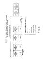
- FIG. 36 is a diagram illustrating a measurement period and a measurement time in the conventional technique for measurement of delay profiles.
- the measurement period is a period of repetition of measurement of a delay profile with each spreading code
- the measurement time is a time necessary for performing an operation of measurement of a delay profile with a single spreading code.
- the measurement period T is a sum of n times the measurement time t and a measurement pause time ts, where the measurement time t is a time in which an operation of measurement with each of the first to nth spreading codes is performed.
- the power consumption in the receiver can be reduced by increasing the measurement pause time so as to lengthen the measurement period.
- the measurement period is required to be set in consideration of the balance between reduction of power consumption and enduring of reception quality.
- a minimum necessary time width is fixedly set as the measurement period.
- the conventional technique it is impossible to flexibly change the time utilization rate of the circuit for measuring delay profiles, where the time utilization rate is determined by, for example, a measurement period, a measurement time, a pause time, and the like.
- the present invention is made in view of the above problems, and the object of the present invention is to provide a communication device which measures delay profiles so as to improve transmission quality by changing the measurement period and the measurement time to appropriate values according to conditions for measurement of the delay profiles.
- a communication device for performing wireless communication.
- the communication device comprises: a measurement-period holding unit which holds for measurement of delay profiles values of a measurement period in correspondence with values indicating one or a combination of a wireless condition or a service quality level; a change recognition unit which recognizes a change in at least one of the wireless condition and the service quality level, and notifies a measurement-period acquisition unit of the change; the measurement-period acquisition unit which acquires from the measurement-period holding unit a value of the measurement period corresponding to the change of which the measurement-period acquisition unit is notified by the change recognition unit; and a delay-profile measurement unit which repeats the measurement of the delay profiles with the measurement period determined by the value acquired by the measurement-period acquisition unit during a time which is necessary and appropriate for the measurement.
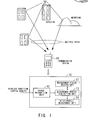
- FIG. 1 is a diagram illustrating a basic construction of the communication device according to the present invention.
- the communication device 10 is a mobile communication device, such as a mobile telephone, which performs wireless communications under a multipath environment.
- the measurement-period holding unit 11 holds values of a measurement period (for delay profile measurement) in correspondence with values indicating one or a combination of a wireless condition and a service quality level. Specifically, the measurement-period holding unit 11 holds values of the measurement period in correspondence with values of the number of spreading codes with which delay profiles are to be measured, which is a wireless condition. Alternatively, the measurement-period holding unit 11 holds values of the measurement period (for delay profile measurement) in correspondence with values of the measurement time (for delay profile measurement), which is determined according to the service quality level.
- the change recognition unit 12 recognizes a change in the wireless condition or the service quality level, and makes a notification of the change. Specifically, the change recognition unit 12 recognizes an increase or decrease in the number of spreading codes as a change in the wireless condition, and notifies a measurement-period acquisition unit 13 of the increase or decrease in the number of spreading codes. Alternatively, the change recognition unit 12 recognizes an increase or decrease in the measurement time (for delay profile measurement) as a change in the service quality level, and notifies the measurement-period acquisition unit 13 of the increase or decrease in the measurement time.
- the measurement-period acquisition unit 13 acquires from the measurement-period holding unit 11 a value of the measurement period corresponding to the information on the change of which the measurement-period acquisition unit 13 is notified. That is, the measurement period is changed according to the above change recognized by the change recognition unit 12.
- the delay-profile measurement unit 14 performs measurement of a delay profile based on the acquired value of the measurement period during a time which is necessary and appropriate for the measurement of the delay profile. Details of the construction and operations of the communication device 10 will be explained later with reference to FIGS. 4 to 35.
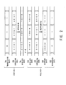
- FIG. 2 is a diagram for explaining a code spread system.
- a data series in the transmission data Ds is multiplied by a spreading code C0 (which is a bit series having a higher bit rate than the transmission data Ds) so as to generate the spread transmission data, and the spread transmission data is converted to wireless data Dr, which is to be outputted.
- a spreading code C0 which is a bit series having a higher bit rate than the transmission data Ds
- each bit “0" in the transmission data Ds is multiplied by the spreading code C0 "01101” so as to generate a bit series "01101”
- each bit "1” in the transmission data Ds is multiplied by the spreading code C0 "01101” so as to generate another bit series "10010.”
- the multiplication is the exclusive OR operation.
- the generated bit series are converted to the wireless data Dr, which is to be outputted.
- the receiver in the example of FIG. 2 holds the same spreading code C0 as that the transmission station uses.
- the receiver receives the wireless data Dr, and down-converts the received wireless data Dr so as to generate reception data D1.
- the receiver despreads the reception data D1 so as to generate despread data D2 by multiplying the reception data D1 by the spreading code C0.
- the receiver multiplies the bit series "01101" in the reception data D1 by the spreading code C0 ("01101") so as to generate a bit series "00000" of the despread data D2, and multiplies each bit series "10010" in the reception data D1 by the spreading code C0 ("01101") so as to generate a bit series "11111" of the despread data D2.
- reproduced data D3 is generated as illustrated in FIG. 2.
- bit values in each timeslot of the despread data for example, "-1" is assigned to each bit “0" in each timeslot of the despread data, "+1” is assigned to each bit “1” in each timeslot of the despread data, and the values assigned to the bits of each timeslot are summed. It is preferable to use a known pilot signal as the reception data D1. In this case, influences of noise components can be suppressed.
- the measurement period is a period in which measurements using an identical spreading code are repeated, where each of the measurements is performed in a measurement time in which a correlation between a received signal and a spreading code can be obtained.
- the measurement period T0 in FIG. 3 corresponds to the measurement period T in FIG. 36.
- a degenerated spreading-code number For example, when a first signal is received from the same source as a second signal for which a delay profile is produced, production of a delay profile of the first signal can be dispensed with.
- the plurality of transmission data series are respectively spread with individual spreading codes.
- it is unnecessary to detect a timeslot boundary in every transmission data series i.e., it is sufficient to choose one of the plurality of transmission data series, and detect a timeslot boundary by using a spreading code with which the chosen transmission data series is spread. Since the plurality of transmission data series are transmitted from an identical source, information on time lags between the plurality of transmission data series is sent from the source. Therefore, it is unnecessary to measure delay profiles of all of the plurality of transmission data series.
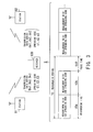
- FIG. 3 is a diagram illustrating a measurement period and a measurement time for delay profile measurement.
- a plurality of transmission data series are transmitted from an identical source.
- the plurality of transmission data series Ds1 to Ds3 which are respectively spread with the spreading codes C1 to C3 are transmitted from the station B1, and the plurality of transmission data series ds1 to ds3 which are respectively spread with the spreading codes c1 to c3 are transmitted from the station B2.
- the receiver 100 selects the transmission data series Ds1 from among the plurality of transmission data series Ds1 to Ds3 transmitted from the station B1, and detects a leading edge of a timeslot of the transmission data series Ds1 by using the spreading code C1.
- the receiver 100 selects the transmission data series ds1 from among the plurality of transmission data series ds1 to ds3 transmitted from the station B2, and detects a timeslot boundary of the transmission data series ds1 by using the spreading code c1.
- the measurement time t0a in which the transmission data series Ds1 is measured by using the spreading code C1 the measurement time t0b in which the transmission data series ds1 is measured by using the spreading code c1
- the measurement pause time ts0 the measurement period T0 for delay profile measurement have a relationship as illustrated in FIG. 3.
- delay profiles are measured by changing the measurement period according to increase or decrease in the number of spreading codes.
- FIG. 4 is a diagram illustrating a construction of the communication device in the first embodiment of the present invention.
- the communication device 10a holds values of the measurement period in correspondence with values of the number of spreading codes with which delay profiles are to be measured, changes the measurement period in response to increase or decrease in the number of spreading codes, and measures delay profiles.
- the communication device 10a comprises a measurement-period holding unit 11a, a change recognition unit 12a, a measurement-period acquisition unit 13a, and a delay-profile measurement unit 14a.
- the change recognition unit 12a comprises a spreading-code determination unit 12a-1 and a measurement-time determination unit 12a-2.
- the delay-profile measurement unit 14a comprises a delay-profile-measurement control unit 14a-1, a timer 14a-2, and a delay-profile-measurement execution unit 14a-3.
- the operations (for performing a method for measuring delay profiles) of the communication device according to the first embodiment are as follows.
- FIG. 5 is a diagram illustrating a management table in the first embodiment.
- the management table 11a-1 is a table which is held in the measurement-period holding unit 11a, and indicates correspondences between the possible values of the number of spreading codes and the applicable values of the measurement period.
- the applicable values of the measurement period are determined in advance under the condition that the number of spreading codes is in the range from 1 to 48, and a delay profile is measured with each spreading code one by one in a measurement time of 4 milliseconds.
- FIG. 6 is a diagram illustrating a state before the number of the spreading codes increases or decreases in the first embodiment, where the spreading codes are detected by the spreading-code determination unit 12a-1 in FIG. 4 as spreading codes with which delay profile measurement is to be performed.
- FIG. 7 is a diagram illustrating a state in the first embodiment in which the number of the spreading codes is increased, and the measurement period is not changed.
- the measurement period is 100 milliseconds (according to FIG. 5). That is, the measurement period is not changed. Therefore, in this case, the communication device operates as illustrated in FIG. 7.
- FIG. 8 is a diagram illustrating a state in the first embodiment in which the number of the spreading codes is increased, and the measurement period is changed.
- the measurement period becomes 200 milliseconds (according to FIG. 5). That is, the measurement period is changed. Therefore, in this case, the communication device operates as illustrated in FIG. 8.
- FIG. 9 is a diagram illustrating a state in the first embodiment in which the number of the spreading codes is decreased, and the measurement period is not changed.
- the measurement period is 100 milliseconds (according to FIG. 5). That is, the measurement period is not changed. Therefore, in this case, the communication device operates as illustrated in FIG. 9.
- FIG. 10 is a diagram illustrating a state in the first embodiment in which the number of the spreading codes is decreased, and the measurement period is changed.
- the measurement period becomes 50 milliseconds (according to FIG. 5). That is, the measurement period is changed. Therefore, in this case, the communication device operates as illustrated in FIG. 10.
- delay profiles are measured by changing the measurement period according to increase or decrease in the measurement time, which is determined according to reception quality.
- FIG. 11 is a diagram illustrating a communication device in the second embodiment of the present invention.
- the communication device 10b holds values of the measurement period in correspondence with values indicating a measurement time (for delay profile measurement), changes the measurement period in response to increase or decrease in the measurement time, and measures delay profiles, where the measurement time is determined according to reception quality.
- the communication device 10b comprises a measurement-period holding unit 11b, a change recognition unit 12b, a measurement-period acquisition unit 13b, and a delay-profile measurement unit 14b.
- the change recognition unit 12b comprises a spreading-code determination unit 12b-1 and a measurement-time determination unit 12b-2.
- the delay-profile measurement unit 14b comprises a delay-profile-measurement control unit 14b-1, a timer 14b-2, and a delay-profile-measurement execution unit 14b-3.
- the operations (for performing a method for measuring delay profiles) of the communication device according to the second embodiment are as follows.
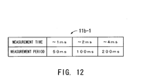
- FIG. 12 is a diagram illustrating a management table in the second embodiment.
- the management table 11b-1 is a table which is held in the measurement-period holding unit 11b, and indicates correspondences between the possible values of the measurement time and the applicable values of the measurement period.
- the applicable values of the measurement period are determined in advance under the condition that the maximum value of the measurement time determined according to the reception quality is 4 milliseconds, and the maximum number of the spreading codes is 48.
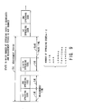
- FIG. 13 is a diagram illustrating a state before the measurement time increases or decreases in the second embodiment.
- the measurement time is 1.5 milliseconds before the measurement time increases or decreases
- FIG. 14 is a diagram illustrating a state in the second embodiment in which the measurement time is increased, and the measurement period is not changed.
- the measurement time is increased from 1.5 milliseconds (as illustrated in FIG. 13) to 2 milliseconds
- the measurement period is 100 milliseconds (according to FIG. 12). That is, the measurement period is not changed. Therefore, in this case, the communication device operates as illustrated in FIG. 14.
- the delay-profile measurement period T12 100 milliseconds
- the delay-profile-measurement pause time ts12 20 milliseconds.
- FIG. 15 is a diagram illustrating a state in the second embodiment in which the measurement time is increased, and the measurement period is changed.
- the measurement time is increased from 1.5 milliseconds (as illustrated in FIG. 13) to 3 milliseconds
- the measurement period becomes 200 milliseconds (according to FIG. 12). That is, the measurement period is changed. Therefore, in this case, the communication device operates as illustrated in FIG. 15.
- the delay-profile measurement period T13 200 milliseconds
- the delay-profile-measurement pause time ts13 80 milliseconds.
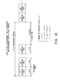
- FIG. 16 is a diagram illustrating a state in the second embodiment in which the measurement time is decreased, and the measurement period is not changed.
- the measurement time is decreased from 1.5 milliseconds (as illustrated in FIG. 13) to 1.2 milliseconds
- the measurement period is 100 milliseconds (according to FIG. 12). That is, the measurement period is not changed. Therefore, in this case, the communication device operates as illustrated in FIG. 16.
- the delay-profile measurement period T14 100 milliseconds
- the delay-profile-measurement pause time ts14 52 milliseconds.
- FIG. 17 is a diagram illustrating a state in the second embodiment in which the measurement time is decreased, and the measurement period is changed.
- the measurement time is decreased from 1.5 milliseconds (as illustrated in FIG. 13) to 0.5 milliseconds
- the measurement period becomes 50 milliseconds (according to FIG. 12). That is, the measurement period is changed. Therefore, in this case, the communication device operates as illustrated in FIG. 17.
- the delay-profile measurement period T15 50 milliseconds
- the delay-profile-measurement pause time ts15 30 milliseconds.
- values of the measurement period are prepared in advance in correspondence with ranges of possible values of the number of spreading codes with which delay profiles are to be measured, or ranges of possible values of the measurement time, which is determined based on information on reception conditions. Therefore, the measurement period can be immediately changed when the number of spreading codes or the measurement time increases or decreases.
- the time utilization rate is determined by, for example, a measurement period, a measurement time, a pause time, and the like. Consequently, the transmission quality can be improved.
- delay profiles are measured by changing the measurement period according to increase or decrease in at least one of the number of spreading codes and the measurement time, which is determined based on information on reception conditions.
- FIG. 18 is a diagram illustrating a communication device in the third embodiment of the present invention.
- the communication device 10c holds values of the measurement period in correspondence with combinations of values of the number of spreading codes (with which delay profiles are measured) and values of the measurement time (for delay profile measurement), which is determined based on information on reception conditions. Then, the communication device 10c changes the measurement period in response to increase or decrease in at least one of the number of spreading codes and the measurement time, and measures delay profiles.
- the communication device 10c comprises a measurement-period holding unit 11c, a change recognition unit 12c, a measurement-period acquisition unit 13c, and a delay-profile measurement unit 14c.
- the change recognition unit 12c comprises a spreading-code determination unit 12c-1 and a measurement-time determination unit 12c-2.
- the delay-profile measurement unit 14c comprises a delay-profile-measurement control unit 14c-1, a timer 14c-2, and a delay-profile-measurement execution unit 14c-3.
- the operations (for performing a method for measuring delay profiles) of the communication device according to the third embodiment are as follows.
- FIG. 19 is a diagram illustrating a management table in the third embodiment.
- the management table 11c-1 is a table which is held in the measurement-period holding unit 11c, and indicates correspondences between the applicable values of the measurement period and combinations of the possible values of the number of the spreading codes and the possible values of the measurement time.
- the applicable values of the measurement period are determined in advance under the condition that the maximum number of the spreading codes is 48, and the maximum value of the measurement time determined according to the reception quality is 4 milliseconds.
- the communication device 10a, 10b, or 10c measures delay profiles based on a value of the measurement period corresponding to one of ranges of values of the measurement time and/or one of ranges of values of the number of spreading codes, where applicable values of the measurement period are held in the measurement-period holding unit 11a, 11b, or 11c in correspondence with the ranges of the values of the measurement time and/or the ranges of values of the number of spreading codes, and the measurement time is determined based on information on reception conditions.
- delay profiles are measured based on a value of the measurement time corresponding to one of ranges of values of the measurement period and/or one of ranges of values of the number of spreading codes, where applicable values of the measurement time are held in a measurement-time holding unit in correspondence with the ranges of the values of the measurement period and/or the ranges of values of the number of spreading codes, and the measurement period is determined based on information on reception conditions.
- delay profiles are measured by changing the measurement time (instead of the measurement period) according to increase or decrease in the number of spreading codes.
- FIG. 20 is a diagram illustrating a communication device in the fourth embodiment of the present invention.
- the communication device 20a holds values of the measurement time in correspondence with values indicating the number of spreading codes with which delay profiles are to be measured, changes the measurement time in response to increase or decrease in the number of spreading codes, and measures delay profiles.
- the communication device 20a comprises a measurement-time holding unit 21a, a change recognition unit 22a, a measurement-time acquisition unit 23a, and a delay-profile measurement unit 24a.
- the change recognition unit 22a comprises a spreading-code determination unit 22a-1 and a measurement-period determination unit 22a-2.
- the delay-profile measurement unit 24a comprises a delay-pro'file-measurement control unit 24a-1, a timer 24a-2, and a delay-profile-measurement execution unit 24a-3.
- the operations (for performing a method for measuring delay profiles) of the communication device according to the fourth embodiment are as follows.
- FIG. 21 is a diagram illustrating a management table in the fourth embodiment.
- the management table 21a-1 is a table which is held in the measurement-time holding unit 21a, and indicates correspondences between the possible values of the number of spreading codes and the applicable values of the measurement time.
- the applicable values of the measurement time are determined in advance under the condition that the possible values of the number of spreading codes range from 1 to 48, and measurement of a delay profile is repeated with a measurement period of 50 milliseconds.
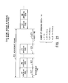
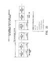
- FIG. 22 is a diagram illustrating a state before the number of the spreading codes increases or decreases in the fourth embodiment.
- FIG. 23 is a diagram illustrating a state in the fourth embodiment in which the number of the spreading codes is increased, and the measurement time is not changed.
- the spreading-code determination unit 22a-1 notifies that the number of the spreading codes is increased from 16 (as illustrated in FIG. 22) to 20, the measurement time is 2 milliseconds (according to FIG. 21). That is, the measurement time is not changed. Therefore, in this case, the communication device operates as illustrated in FIG. 23.
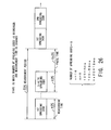
- FIG. 24 is a diagram illustrating a state in the fourth embodiment in which the number of the spreading codes is increased, and the measurement time is changed.
- the measurement time becomes 1 millisecond (according to FIG. 21). That is, the measurement time is changed. Therefore, in this case, the communication device operates as illustrated in FIG. 24.
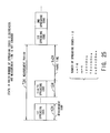
- FIG. 25 is a diagram illustrating a state in the fourth embodiment in which the number of the spreading codes is decreased, and the measurement time is not changed.
- the measurement time is 2 milliseconds (according to FIG. 21). That is, the measurement time is not changed. Therefore, in this case, the communication device operates as illustrated in FIG. 25.
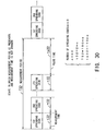
- FIG. 26 is a diagram illustrating a state in the fourth embodiment in which the number of the spreading codes is decreased, and the measurement time is changed.
- the measurement time becomes 4 milliseconds (according to FIG. 21). That is, the measurement time is changed. Therefore, in this case, the communication device operates as illustrated in FIG. 26.
- delay profiles are measured by changing the measurement time according to increase or decrease in the measurement period, which is determined according to reception quality.
- FIG. 27 is a diagram illustrating a communication device in the fifth embodiment of the present invention.
- the communication device 20b holds values of the measurement time in correspondence with values indicating the measurement period (for delay profile measurement), changes the measurement time in response to increase or decrease in the measurement period, and measures delay profiles, where the measurement period is determined according to reception quality.
- the communication device 20b comprises a measurement-time holding unit 21b, a change recognition unit 22b, a measurement-time acquisition unit 23b, and a delay-profile measurement unit 24b.
- the change recognition unit 22b comprises a spreading-code determination unit 22b-1 and a measurement-period determination unit 22b-2.
- the delay-profile measurement unit 24b comprises a delay-profile-measurement control unit 24b-1, a timer 24b-2, and a delay-profile-measurement execution unit 24b-3.
- the operations (for performing a method for measuring delay profiles) of the communication device according to the fifth embodiment are as follows.
- FIG. 28 is a diagram illustrating a management table in the fifth embodiment.
- the management table 21b-1 is a table which is held in the measurement-time holding unit 21b, and indicates correspondences between the possible values of the measurement period and the applicable values of the measurement time.
- the applicable values of the measurement time are determined in advance under the condition that the measurement period determined based on information reception conditions is in the range from 50 to 400 milliseconds, and the maximum number of the spreading codes is 48.
- FIG. 29 is a diagram illustrating a state before the measurement period increases or decreases in the fifth embodiment.
- the measurement period is 150 milliseconds before the measurement period increases or decreases
- FIG. 30 is a diagram illustrating a state in the fifth embodiment in which the measurement period is increased, and the measurement time is not changed.
- the measurement period is increased from 150 milliseconds (as illustrated in FIG. 29) to 190 milliseconds
- the measurement time is 2 milliseconds (according to FIG. 28). That is, the measurement time is not changed. Therefore, in this case, the communication device operates as illustrated in FIG. 30.
- the delay-profile measurement period T32 190 milliseconds
- the delay-profile-measurement pause time ts32 110 milliseconds.
- FIG. 31 is a diagram illustrating a state in the fifth embodiment in which the measurement period is increased, and the measurement time is changed.
- the measurement period is increased from 150 milliseconds (as illustrated in FIG. 29) to 300 milliseconds, the measurement time becomes 4 milliseconds (according to FIG. 28). That is, the measurement time is changed. Therefore, in this case, the communication device operates as illustrated in FIG. 31.
- the delay-profile measurement period T33 300 milliseconds
- the delay-profile-measurement pause time ts33 140 milliseconds.
- FIG. 32 is a diagram illustrating a state in the fifth embodiment in which the measurement period is decreased, and the measurement time is not changed.
- the measurement period is decreased from 150 milliseconds (as illustrated in FIG. 29) to 100 milliseconds
- the measurement time is 2 milliseconds (according to FIG. 28). That is, the measurement time is not changed. Therefore, in this case, the communication device operates as illustrated in FIG. 32.
- the delay-profile measurement period T34 100 milliseconds
- the delay-profile-measurement pause time ts34 20 milliseconds.
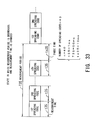
- FIG. 33 is a diagram illustrating a state in the fifth embodiment in which the measurement period is decreased, and the measurement time is changed.
- the measurement period is decreased from 150 milliseconds (as illustrated in FIG. 29) to 50 milliseconds, the measurement time becomes 1 millisecond (according to FIG. 28). That is, the measurement time is changed. Therefore, in this case, the communication device operates as illustrated in FIG. 33.
- the delay-profile measurement period T35 50 milliseconds
- the delay-profile-measurement pause time ts35 10 milliseconds.
- delay profiles are measured by changing the measurement time according to increase or decrease in at least one of the number of spreading codes and the measurement period, which is determined based on information on reception conditions.
- FIG. 34 is a diagram illustrating a communication device in the sixth embodiment of the present invention.
- the communication device 20c holds values of the measurement time in correspondence with combinations of values of the number of spreading codes (with which delay profiles are measured) and values of the measurement period (for delay profile measurement), changes the measurement time in response to increase or decrease in at least one of the number of spreading codes and the measurement period, and measures delay profiles, where the measurement period is determined based on information on reception conditions.
- the communication device 20c comprises a measurement-time holding unit 21c, a change recognition unit 22c, a measurement-time acquisition unit 23c, and a delay-profile measurement unit 24c.
- the change recognition unit 22c comprises a spreading-code determination unit 22c-1 and a measurement-period determination unit 22c-2.
- the delay-profile measurement unit 24c comprises a delay-profile-measurement control unit 24c-1, a timer 24c-2, and a delay-profile-measurement execution unit 24c-3.
- the operations (for performing a method for measuring delay profiles) of the communication device according to the sixth embodiment are as follows.
- FIG. 35 is a diagram illustrating a management table in the sixth embodiment.
- the management table 21c-1 is a table which is held in the measurement-time holding unit 21c, and indicates correspondences between the applicable values of the measurement time and combinations of the possible values of the number of the spreading codes and the possible values of the measurement period.
- the applicable values of the measurement time are determined in advance under the condition that the number of the spreading codes is in the range from 1 to 48, and the measurement period determined based on information reception conditions is in the range from 50 to 400 milliseconds.
- values of the measurement time are prepared in advance in correspondence with ranges of possible values of the number of spreading codes with which delay profiles are to be measured, or ranges of possible values of the measurement period, which is determined based on information on reception conditions. Therefore, it is possible to immediately change the measurement time when the number of spreading codes or the measurement period increases or decreases.
- the communication device is arranged to have such a construction as to hold values of the measurement period (for delay profile measurement) in correspondence with values indicating one or a combination of a wireless condition and a service quality level, and performs measurement of delay profiles based on a value of the measurement period corresponding to a value indicating one or a combination of the wireless condition and the service quality level. Therefore, the communication device according to the present invention can change the measurement period to an appropriate value for delay profile measurement, according to measurement conditions. Thus, the transmission quality can be improved.
Landscapes
- Engineering & Computer Science (AREA)
- Computer Networks & Wireless Communication (AREA)
- Signal Processing (AREA)
- Power Engineering (AREA)
- Quality & Reliability (AREA)
- Mobile Radio Communication Systems (AREA)
- Monitoring And Testing Of Transmission In General (AREA)
Abstract
Description
Claims (12)
- A communication device for performing wireless communication, comprising:a measurement-period holding unit which holds for measurement of delay profiles values of a measurement period in correspondence with values indicating one or a combination of a wireless condition or a service quality level;a change recognition unit which recognizes a change in at least one of the wireless condition and the service quality level, and notifies a measurement-period acquisition unit of the change;said measurement-period acquisition unit which acquires from said measurement-period holding unit a value of the measurement period corresponding to said change of which the measurement-period acquisition unit is notified by the change recognition unit; anda delay-profile measurement unit which repeats the measurement of the delay profiles with the measurement period determined by said value acquired by the said measurement-period acquisition unit during a time which is necessary and appropriate for the measurement.
- The communication device according to claim 1, wherein said measurement-period holding unit holds for the measurement of the delay profiles values of the measurement period in correspondence with values indicating the number of spreading codes with which the delay profiles are to be measured, as said wireless condition, and said change recognition unit recognizes increase or decrease in the number of spreading codes as a change in the wireless condition.
- The communication device according to claim 1, wherein said measurement-period holding unit holds for the measurement of the delay profiles values of the measurement period in correspondence with values indicating the measurement time as information indicating said service quality level, the measurement time is determined for the measurement of the delay profiles according to reception quality, and said change recognition unit recognizes increase or decrease in the measurement time as a change in the service quality level.
- The communication device according to claim 1, wherein said measurement-period holding unit holds for the measurement of the delay profiles values of the measurement period in correspondence with combinations of values of the number of spreading codes with which the delay profiles are to be measured and values of a measurement time which is determined for the measurement of the delay profiles according to reception quality, as combinations of said wireless condition and said service quality level, and said change recognition unit recognizes increase or decrease in at least one of the number of spreading codes and the measurement time as said change in at least one of the wireless condition and the service quality level.
- A communication device for performing wireless communication, comprising:a measurement-time holding unit which holds for measurement of delay profiles values of a measurement time in correspondence with values indicating one or a combination of a wireless condition or a service quality level;a change recognition unit which recognizes a change in at least one of the wireless condition and the service quality level, and notifies a measurement-time acquisition unit of the change;said measurement-time acquisition unit which acquires from said measurement-period holding unit a value of the measurement time corresponding to said change of which the measurement-time acquisition unit is notified by the change recognition unit; anda delay-profile measurement unit which performs the measurement of the delay profiles for the measurement time determined by said value acquired by the said measurement-time acquisition unit, within a time which is necessary and appropriate for the measurement.
- The communication device according to claim 5, wherein said measurement-time holding unit holds for the measurement of the delay profiles values of the measurement time in correspondence with values indicating the number of spreading codes with which the delay profiles are to be measured, as said wireless condition, and said change recognition unit recognizes increase or decrease in the number of spreading codes as a change in the wireless condition.
- The communication device according to claim 5, wherein said measurement-time holding unit holds for the measurement of the delay profiles values of the measurement time in correspondence with values indicating the measurement period as said service quality level, the measurement period is determined for the measurement of the delay profiles according to reception quality, and said change recognition unit recognizes increase or decrease in the measurement period as a change in the service quality level.
- The communication device according to claim 5, wherein said measurement-time holding unit holds for the measurement of the delay profiles values of the measurement time in correspondence with combinations of values of the number of spreading codes with which the delay profiles are to be measured and values of a measurement period which is determined for the measurement of the delay profiles according to reception quality, as combinations of said wireless condition and said service quality level, and said change recognition unit recognizes increase or decrease in at least one of the number of spreading codes and the measurement period as said change in at least one of the wireless condition and the service quality level.
- A method for measuring delay profiles, comprising the steps of:(a) holding for measurement of the delay profiles values of a measurement period in correspondence with values indicating one or a combination of the number of spreading codes with which the delay profiles are to be measured and a measurement time which is determined for the measurement of the delay profiles according to reception quality;(b) recognizing a change in at least one of the number of spreading codes and the measurement time;(c) changing said measurement period according to said change; and(d) repeating the measurement of the delay profiles with the changed measurement period within a time which is necessary and appropriate for the measurement.
- A method for measuring delay profiles, comprising the steps of:(a) holding for measurement of the delay profiles values of a measurement time in correspondence with values indicating one or a combination of the number of spreading codes with which the delay profiles are to be measured and a measurement period which is determined for the measurement of the delay profiles according to reception quality;(b) recognizing a change in at least one of the number of spreading codes and the measurement period;(c) changing said measurement time according to said change; and(d) performing the measurement of the delay profiles with the changed measurement time within a time which is necessary and appropriate for the measurement.
- A receiver receiving spread-spectrum wireless signals, and having a function of generating, as information on delay profiles, information on correlation between received signals and spreading codes for detection of timings of delayed waves, wherein:when there are a plurality of spreading codes with which the information on the delay profiles is to be generated, said function sets each of the plurality of spreading codes in succession in a correlation detection unit which is provided for measuring the correlations, and detection of the correlations with each of the plurality of spreading codes is repeated with a predetermined period; andsaid receiver comprises an updating unit which increases said predetermined period when the number of the plurality of spreading codes increases, or when a measurement time in which each of the correlations is measured with each of the plurality of spreading codes increases.
- A receiver for receiving spread-spectrum wireless signals, and generating delay profiles which indicate timings of delayed portions of the spread-spectrum wireless signals, comprising:a correlation detection unit which holds in succession each of a plurality of spreading codes which are used for generating the delay profiles, obtains correlations between the spread-spectrum wireless signals and the plurality of spreading codes by measurement repeated with a measurement period which is predetermined for each of the plurality of spreading codes, and generates the delay profiles based on the correlations; anda measurement-period change unit which increases said measurement period when the number of the plurality of spreading codes increases, or when a measurement time in which each of the correlations is obtained by measurement with each of the plurality of spreading codes increases.
Applications Claiming Priority (2)
| Application Number | Priority Date | Filing Date | Title |
|---|---|---|---|
| JP2002341961A JP2004179835A (en) | 2002-11-26 | 2002-11-26 | Communication device |
| JP2002341961 | 2002-11-26 |
Publications (2)
| Publication Number | Publication Date |
|---|---|
| EP1424785A2 true EP1424785A2 (en) | 2004-06-02 |
| EP1424785A3 EP1424785A3 (en) | 2005-11-30 |
Family
ID=32290403
Family Applications (1)
| Application Number | Title | Priority Date | Filing Date |
|---|---|---|---|
| EP20030257367 Withdrawn EP1424785A3 (en) | 2002-11-26 | 2003-11-21 | Spread spectrum communication device |
Country Status (3)
| Country | Link |
|---|---|
| US (1) | US20040106421A1 (en) |
| EP (1) | EP1424785A3 (en) |
| JP (1) | JP2004179835A (en) |
Cited By (1)
| Publication number | Priority date | Publication date | Assignee | Title |
|---|---|---|---|---|
| WO2018227632A1 (en) * | 2017-06-16 | 2018-12-20 | Oppo广东移动通信有限公司 | Cell measurement method, terminal device and network device |
Families Citing this family (10)
| Publication number | Priority date | Publication date | Assignee | Title |
|---|---|---|---|---|
| GB2435984B (en) * | 2006-03-06 | 2008-05-14 | Motorola Inc | Service characteristic evaluation in a cellular communication system |
| US8902154B1 (en) | 2006-07-11 | 2014-12-02 | Dp Technologies, Inc. | Method and apparatus for utilizing motion user interface |
| US8949070B1 (en) | 2007-02-08 | 2015-02-03 | Dp Technologies, Inc. | Human activity monitoring device with activity identification |
| US7753861B1 (en) | 2007-04-04 | 2010-07-13 | Dp Technologies, Inc. | Chest strap having human activity monitoring device |
| TW200908760A (en) * | 2007-05-22 | 2009-02-16 | Nec Corp | Signal handover control device, method and program |
| US8555282B1 (en) | 2007-07-27 | 2013-10-08 | Dp Technologies, Inc. | Optimizing preemptive operating system with motion sensing |
| US8195122B1 (en) * | 2007-12-14 | 2012-06-05 | Dp Technologies, Inc. | Method and apparatus for adjusting the frequency of testing for a wireless communications signal |
| US8996332B2 (en) | 2008-06-24 | 2015-03-31 | Dp Technologies, Inc. | Program setting adjustments based on activity identification |
| US8872646B2 (en) | 2008-10-08 | 2014-10-28 | Dp Technologies, Inc. | Method and system for waking up a device due to motion |
| US9529437B2 (en) | 2009-05-26 | 2016-12-27 | Dp Technologies, Inc. | Method and apparatus for a motion state aware device |
Family Cites Families (3)
| Publication number | Priority date | Publication date | Assignee | Title |
|---|---|---|---|---|
| JP3683128B2 (en) * | 1999-07-06 | 2005-08-17 | 日本電気株式会社 | Wireless communication device and power consumption control method for wireless communication device |
| JP2001211101A (en) * | 2000-01-26 | 2001-08-03 | Nec Corp | Low power CDMA receiver and method for reducing power consumption thereof |
| US6650694B1 (en) * | 2000-02-18 | 2003-11-18 | Texas Instruments Incorporated | Correlator co-processor for CDMA RAKE receiver operations |
-
2002
- 2002-11-26 JP JP2002341961A patent/JP2004179835A/en active Pending
-
2003
- 2003-11-21 EP EP20030257367 patent/EP1424785A3/en not_active Withdrawn
- 2003-11-24 US US10/720,433 patent/US20040106421A1/en not_active Abandoned
Cited By (2)
| Publication number | Priority date | Publication date | Assignee | Title |
|---|---|---|---|---|
| WO2018227632A1 (en) * | 2017-06-16 | 2018-12-20 | Oppo广东移动通信有限公司 | Cell measurement method, terminal device and network device |
| US11115851B2 (en) | 2017-06-16 | 2021-09-07 | Guangdong Oppo Mobile Telecommunications Corp., Ltd. | Cell measurement method, terminal device and network device |
Also Published As
| Publication number | Publication date |
|---|---|
| JP2004179835A (en) | 2004-06-24 |
| EP1424785A3 (en) | 2005-11-30 |
| US20040106421A1 (en) | 2004-06-03 |
Similar Documents
| Publication | Publication Date | Title |
|---|---|---|
| JP3930187B2 (en) | Synchronization control method, receiver, base station, and mobile terminal | |
| US6370397B1 (en) | Search window delay tracking in code division multiple access communication systems | |
| JP2937994B1 (en) | Cellular system, mobile portable device, base station device, and optimal path detection method and device | |
| US6085104A (en) | Pilot aided, time-varying finite impulse response, adaptive channel matching receiving system and method | |
| JP4280423B2 (en) | CDMA receiver with multiple rake branches sharing tracking device | |
| JP4350271B2 (en) | Method and apparatus for acquiring spreading code synchronization in receiver of CDMA communication system | |
| US6961352B2 (en) | Method of synchronizing a radio terminal of a radio communication network and a corresponding radio terminal | |
| US7711385B2 (en) | Method and system of transmission power control | |
| AU4263199A (en) | Multipath propagation delay determining means using periodically inserted pilot symbols | |
| CN100415029C (en) | Apparatus and method for estimating initial frequency offset in an asynchronous mobile communication system | |
| EP1279239B1 (en) | Matched filter and receiver for mobile radio communication system | |
| US7330447B2 (en) | Cell search method in CDMA capable of carrying out a cell search processing at a high speed | |
| KR100361408B1 (en) | Synchronous capture circuit for code division multiple access communication | |
| US20040106421A1 (en) | Communication device | |
| JP4255601B2 (en) | Method for establishing synchronization of mobile stations in a mobile communication system | |
| KR100504360B1 (en) | Receiver and reception method | |
| EP1628409B1 (en) | A power level measuring device and a mobile station | |
| KR100558113B1 (en) | Fading Adaptive Space-Time Array Receiving System and Method thereof | |
| JP4361703B2 (en) | Radio service area evaluation equipment | |
| KR100337389B1 (en) | Apparatus for acquisition of synchronization of PN signal using matching filter in digital communication system and method therefor | |
| US20100278115A1 (en) | Wireless Base Station Apparatus, Frequency Deviation Detecting Method, And Mobile Communication System | |
| KR102869663B1 (en) | Apparatus and method for estimating frequency offset based on correlation value | |
| JP3992459B2 (en) | Receiving device, receiving method, and semiconductor device | |
| US20050083898A1 (en) | Communication control apparatus, and CDMA communication system using the same | |
| EP1392010A1 (en) | Transmission power control circuit using w-cdma method |
Legal Events
| Date | Code | Title | Description |
|---|---|---|---|
| PUAI | Public reference made under article 153(3) epc to a published international application that has entered the european phase |
Free format text: ORIGINAL CODE: 0009012 |
|
| AK | Designated contracting states |
Kind code of ref document: A2 Designated state(s): AT BE BG CH CY CZ DE DK EE ES FI FR GB GR HU IE IT LI LU MC NL PT RO SE SI SK TR |
|
| AX | Request for extension of the european patent |
Extension state: AL LT LV MK |
|
| PUAL | Search report despatched |
Free format text: ORIGINAL CODE: 0009013 |
|
| AK | Designated contracting states |
Kind code of ref document: A3 Designated state(s): AT BE BG CH CY CZ DE DK EE ES FI FR GB GR HU IE IT LI LU MC NL PT RO SE SI SK TR |
|
| AX | Request for extension of the european patent |
Extension state: AL LT LV MK |
|
| RIC1 | Information provided on ipc code assigned before grant |
Ipc: 7H 04L 25/02 B Ipc: 7H 04L 1/00 B Ipc: 7H 04B 1/707 A |
|
| 17P | Request for examination filed |
Effective date: 20060322 |
|
| AKX | Designation fees paid |
Designated state(s): DE FR GB |
|
| 17Q | First examination report despatched |
Effective date: 20071009 |
|
| STAA | Information on the status of an ep patent application or granted ep patent |
Free format text: STATUS: THE APPLICATION IS DEEMED TO BE WITHDRAWN |
|
| 18D | Application deemed to be withdrawn |
Effective date: 20080220 |