The present invention relates to a slope efficiency measurement apparatus of the
type used, for example, to measure performance of a laser device, such as a
semiconductor laser diode used in transmitters in an optical communications
network. An example of the optical communications network is a Synchronous
Optical NETwork (SONET). The present invention also relates to a method of
measuring slope efficiency for the laser device.
In an optical communications network, a number of transmitter modules are
provided for transmitting data. A transmitter module typically comprises a
semiconductor laser diode, the laser diode having an associated characteristic
curve of output power of light emitted by the laser device versus input current.
The characteristic curve has an initial linear portion which extends from an origin
and has a very slight upward slope. The initial linear portion is then followed, with
increasing input current, by a sharp bend. The characteristic curve then has an
operating portion having a relatively steep gradient, the operating portion being
substantially linear. The input current corresponding to the sharp bend is known
as a threshold current point, emissions by the laser device at currents below the
threshold current point being incoherent and emissions by the laser device at
currents above the threshold current point being stimulated coherent emissions.
Knowledge of the threshold current point and the gradient of the linear operating
portion, referred to as the slope efficiency or differential efficiency, of the laser
device is important in order to drive the laser device accurately and efficiently.
However, the position of the threshold current point and the slope efficiency vary
with temperature and age of the laser device and so it is necessary to monitor the
threshold current point and the slope efficiency of the laser device during operation
of the laser device in order to control a bias current and/or a modulation current
signal applied to the laser device, thereby controlling the, so-called, extinction ratio
of the laser device. The bias current is applied to the laser device in order to make
the laser device operate in the linear operating portion of the characteristic curve.
The modulation current signal is applied to the laser device to modulate the
electromagnetic energy, emitted by the laser device in the linear operating portion,
with data to be transmitted, the data being borne by the modulation current signal.
The extinction ratio of the laser device is the ratio of the output power of the laser
device corresponding to the transmission of a logic "1" to the output power
corresponding to the transmission of a logic "0". Typically, the extinction ration is
set to a value close to 10. Accurate discrimination between logic 1 s and logic 0s is
facilitated by high values of extinction ratio, but the output power performance of
the laser device becomes nonlinear when output power corresponding to logic 0 is
close to the output power at the threshold current point, increasing the degradation
caused by chromatic dispersion. Movement of the extinction ratio away from the
set value results in an increase in the bit error rate of the optical communications
network. It is thus important that the extinction ratio is maintained close to the set
value over the optimum operating conditions and the life of the transmitter module.
US 6,414,974 discloses a method and control circuit for controlling an extinction
ratio. The slope of an operating portion of the laser diode is determined by
increasing the magnitude of the modulation current signal, Im, by an incremental
test amount, ΔIm , the incremental test amount, ΔIm, being a small percentage of
the magnitude of the modulation current signal, Im. In response to increasing the
magnitude of the modulation current signal by the incremental test amount, ΔIm, a
corresponding increase, ΔPav, in average power, Pav, output by the laser diode
results. The corresponding increase ΔPav is determined and compared to a power
increment reference value, ΔPavref. If the corresponding increase, ΔPav, differs
from the power increment reference value, ΔPavref, a correction is applied to the
magnitude of the modulation current signal, Im. US 6,414,974 states that the
incremental test amount ΔIm, should be sufficiently small so as not to affect normal
operation of the laser diode and, in one embodiment disclosed therein, the
incremental test amount, ΔIm, does not exceed 5% of the magnitude of the
modulation current signal, Im, and preferably does not exceed 1% of the magnitude
of the modulation current signal, Im.
Whilst US 6,414,974 requires the incremental test amount, ΔIm, to be relatively
small in order to avoid impairment of transmission of data by the laser diode, such
a requirement compromises the accuracy of the calculation of the slope efficiency
associated with the laser diode. For example, the increase ΔPav in the average
power, Pav, for a 1% increase in the incremental test amount, ΔIm, can be
represented by either two or three bits, a possible error of 50%, if eight bit
digitisation is used. The error is reduced if a larger increase in the incremental test
amounts, ΔIm, is used but the impairment of transmission of data will increase
correspondingly. Consequently, the threshold current point, Ith, associated with
the laser diode cannot be calculated with accuracy, making control of the bias
current applied to the laser diode inaccurate, and thus causing the extinction ration
to depart from its optimum value.
According to a first aspect of the present invention, there is provided a method of
measuring slope efficiency for a laser device, the method comprising the steps of:
altering a modulation current signal for driving the laser device; tapping a
predetermined amount of electromagnetic radiation generated by stimulated
emission in response to the modulation current signal; measuring the power of the
tapped predetermined amount of electromagnetic radiation; characterised by the
steps of: attenuating untapped electromagnetic radiation; and calculating the slope
efficiency using knowledge of the alteration of the modulation current signal and
the measured power of the tapped predetermined amount of electromagnetic
radiation.
Preferably, the magnitude of the modulation current signal is altered by at least
about 5% of the magnitude of the modulation current signal prior to alteration
thereof. More preferably, the magnitude of the modulation current signal is altered
by between about 5% and about 10% of the magnitude of the modulation current
signal prior to alteration thereof.
Preferably, the modulation current signal is altered by providing the modulation
current signal with a sinusoidal component, the frequency of the sinusoidal
component being below a data rate for communicating data using the modulation
current signal.
Preferably, the method further comprises the steps of: measuring the attenuated
untapped electromagnetic radiation; and controlling the attenuation of the
untapped electromagnetic radiation in response to the measurement of the
attenuated untapped electromagnetic radiation.
Alternatively, the step of attenuating the untapped electromagnetic radiation
further comprises: attenuating the untapped electromagnetic radiation by a
predetermined amount.
In a first embodiment of the invention, a method of measuring a threshold current
point for a laser device comprises the method of measuring slope efficiency as set
forth above in accordance with the first aspect of the present invention. However,
the method further comprises the step of: using the calculated slope efficiency to
calculate the threshold current point.
In a second embodiment of the invention, a method of controlling a bias current for
a laser device comprises the steps of: measuring the threshold current point in
accordance with the method of measuring the threshold current point as set forth
above in accordance with the first embodiment; and adjusting the bias current in
response to the measured threshold current point.
In a third embodiment of the invention, a method of controlling a modulation
current signal for a laser device comprises the steps of: measuring the slope
efficiency in accordance with the method of measuring slope efficiency as set forth
above in accordance with the first aspect of the present invention; and adjusting
the modulation current signal in response to the measured slope efficiency.
In a fourth embodiment of the invention, a method of controlling an extinction ratio
for a laser device comprises the method of controlling the bias current as set forth
above in accordance with the second embodiment and/or the method of controlling
the modulation current signal as set forth above in accordance with the third
embodiment.
According to a second aspect of the invention, there is provided a slope efficiency
measurement apparatus for a laser device, the apparatus comprising: a
modulation current driver unit coupled to a control unit, the control unit being
arranged to control alteration of a modulation current signal generated by the
modulation current driver unit; a tap for tapping a predetermined amount of
electromagnetic radiation generated by stimulated emission in response to the
modulation current signal; a power measurement unit for measuring the power of
the tapped predetermined amount of electromagnetic radiation; characterised by:
an attenuator for attenuating untapped electromagnetic radiation; and the control
unit being arranged to calculate the slope efficiency using knowledge of the
alteration of the modulation current signal and the measured power of the tapped
predetermined amount of electromagnetic radiation.
Preferably, the control unit is arranged to alter the magnitude of the modulation
current signal by at least about 5% of the magnitude of the modulation current
signal prior to alteration thereof. More preferably, the control unit is arranged to
alter the magnitude of the modulation current signal by between about 5% and
about 10% of the magnitude of the current signal prior to alteration thereof.
Preferably, the control unit is arranged to alter the modulation current signal by
providing the modulation current signal with a sinusoidal component, the
frequency of the sinusoidal component, when in use, being below a data rate for
communicating data using the modulation current signal.
Preferably, the apparatus further comprises: a further power measurement unit for
measuring power of the attenuated untapped electromagnetic radiation; and the
control unit is further arranged to control attenuation of the untapped
electromagnetic radiation in response to the measurement of the attenuated
untapped electromagnetic radiation. Alternatively, the control unit may be further
arranged to attenuate the untapped electromagnetic radiation by a predetermined
amount.
In the first embodiment of the invention, a threshold current point measurement
apparatus for a laser device, comprises: the slope efficiency measurement
apparatus as set forth above in accordance with the second aspect of the present
invention, and wherein: the control unit is further arranged to calculate the
threshold current point using the calculated slope efficiency.
In the second embodiment, a bias current control apparatus for a laser device,
comprises: the threshold current point measurement apparatus as set forth above
in accordance with the second embodiment; and a bias current driver unit coupled
to the control unit; wherein: the control unit is arranged to adjust a bias current
generated by the bias current driver unit in response to the measured threshold
current point.
In the third embodiment, a modulation current control apparatus for a laser device,
comprises: the slope efficiency measurement apparatus as set forth above in
accordance with the second aspect of the present invention; and wherein: the
control unit is further arranged to adjust the modulation current signal in response
to the measured slope efficiency.
In the fourth embodiment, an extinction ratio control apparatus for a laser device,
comprises the bias current control apparatus as set forth above in accordance with
the second embodiment and/or the modulation current control apparatus as set
forth above in accordance with the third embodiment.
It is thus possible to provide a slope efficiency measurement apparatus and a
method therefor that can measure slope efficiency associated with a laser device
more accurately than known apparatus and methods. Consequently, the threshold
current point associated with the laser device can also be determined with greater
accuracy than with known apparatus and methods. In addition, the improved
accuracy in measurement is achieved without impairment of the optical data signal
emitted by the laser device. It is thus also possible to control the bias current
and/or the magnitude of the modulation current signal applied to the laser device,
and hence the extinction ratio of the laser device, with greater precision than with
known apparatus and methods. As a consequence, less margin can be provided
between a set-up value of the extinction ratio and a specification limit of the laser
device. Generally, a margin is provided between the set-up value and the
specification limit so that deficiencies in the control of the extinction ratio do not
cause the extinction ratio to vary outside the specification limit, thereby improving
bit error rate when transmitting signals over dispersive optical fibre.
At least one embodiment of the invention will now be described, by way of
example only, with reference to the accompanying drawings, in which:
Referring to Figure 1, a transmitter module 100 comprises a laser diode 102
having an input 103 coupled to an output 104 of a bias current supply circuit 106
and an output 108 of a modulation current supply circuit 110. A first output 112 of
a control unit 114 is coupled to an input 116 of the bias current supply circuit 106,
and a second output 118 of the control unit 114 is coupled to an input 120 of the
modulation current supply circuit 110.
An optical attenuator 122, for example a Micro-Electro-Mechanical System
(MEMS) optical attenuator or a Liquid Crystal (LC) optical attenuator, or any other
known optical attenuator, is disposed opposite the laser diode 102 in a first
propagation path 124 extending from a first optical output 126, for example a front
facet, of the laser diode 102 to an input port 128 of the attenuator 122. A control
input 130 of the attenuator 122 is coupled to a third output 132 of the control unit
114.
A first tap 134, for example a first 99:1 beam splitter, is disposed in the first
propagation path 124 and positioned relative the laser diode 102 and the
attenuator 122 so as to maintain the first propagation path 124 and create a
second propagation path 136 substantially perpendicular to the first propagation
path 124. The second propagation path 136 extends from the first tap 134 to an
input port 138 of a first power measurement unit 140, an output 142 of the first
power measurement unit 140 being coupled to a first input 144 of the control unit
114.
Alternatively, the input port 138 of the first power measurement unit 140 can be
disposed adjacent another optical output (not shown) of the laser diode 102, for
example, a back facet. In this embodiment, the second propagation path 124 can
extend from the back facet of the laser diode 102 to the input port 138 of the first
power measurement unit 140. Consequently, the first tap 134 is not required.
A third propagation path 146 extends from an output port 148 of the attenuator
122. Optionally, a second tap 150, for example a second 99:1 beam splitter, is
disposed in the third propagation path 146 relative to the output port 148 of the
attenuator 122 so as to maintain the third propagation path 146 and create a fourth
propagation path 152 substantially perpendicular to the third propagation path 146.
The fourth propagation path 152 extends from the second tap 150 to an input port
154 of a second power measurement unit 156, an output 158 of the second power
measurement unit 156 being coupled to a second input 160 of the control unit 114.
Whilst, in this example, the control unit 114 is a single unit, it should be understood
that the control unit 114 can comprise any number of sub-components, for
example controllers, processors and/or co-processors.
In operation, the control unit 114 sends a first control signal to the bias current
supply circuit 106 and the bias current supply circuit 106 applies a first driver
signal to the laser diode 102 in order to provide a bias current, Ib, of sufficiently
high amplitude to cause the laser diode 102 to be in an operating mode in which
light is generated by the laser diode 102 by the process of stimulated emission.
A data signal to be transmitted by the laser diode 102 is received at an input (not
shown) of the control unit 114 and a second control signal is generated by the
control unit 114 in response to the received data signal. The second control signal
is received by the modulation current supply circuit 110, which generates a
modulation current driver signal, Im, in response to the received second control
signal. The application of the modulation current signal, Im, serves to modulate the
light generated by the laser diode 102 with the data signal.
In terms of an optical output power v. input current characteristic curve, the bias
current, Ib, is applied to ensure that the laser diode 102 operates in the operating
portion of the characteristic curve, i.e. above the threshold point, Ith, of the laser
diode 102.
Light emitted by the laser diode 102 is incident upon the first tap 134 and a first
small proportion, for example 1%, of the light emitted by the laser diode 102 is
directed along the second propagation path 136 to the input port 138 of the first
power measurement unit 140 by the first tap 134. The first small proportion of the
emitted light is incident upon a sensor (not shown) of the first power measurement
unit 140 and the first power measurement unit 140 generates a first average
power measurement signal in response to the incidence of the first small
proportion of the light emitted by the laser diode 102.
A first remaining, untapped, proportion of the emitted light continues propagation
along the first propagation path 124 to the input port 128 of the attenuator 122 and
is attenuated by an attenuation factor dictated by an attenuation control signal
issued by the control unit 114. When the slope efficiency, ηS, of the laser diode
102 is not being measured, substantially no attenuation of the first, untapped,
proportion of the emitted light takes place.
If the optional second tap 150 and the second power measurement unit 156 are
provided, light output from the attenuator 122 follows the third propagation path
146 and is incident upon the second tap 150 whereupon a second small
proportion, for example 1%, of the light output from the attenuator 122 is directed
along the fourth propagation path 152 to the second power measurement unit 156.
The second proportion of the light output from the attenuator 122 is incident upon
a sensor (also not shown) of the second power measurement unit 156 and the
second power measurement unit 156 generates a second average power
measurement signal in response to the incidence of the second small proportion of
the light output from the attenuator 122. A second remaining, untapped,
proportion of the light output from the attenuator 122 continues propagation along
the third propagation path 146. The onward propagation of the second untapped
proportion of the light output from the attenuator 122 is only relevant to the
invention in so far as the amplitude of the untapped proportion of the light emitted
from the attenuator 122 needs to be within a predetermined range of amplitudes.
Consequently, the onward propagation and destination of the second untapped
proportion of the light output from the attenuator 122 will not be described further
herein.
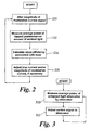
Referring to Figure 2, to measure performance of the laser diode 102 in order to
identify changes in the slope efficiency, ηS, of the laser diode 102, the control unit
114 alters the second control signal (Step 200) so as to alter the amplitude
(magnitude) of the modulation current signal, Im, by a test amount ΔIm. The control
unit 114 monitors the first average power measurement signal in order to measure
(Step 202) a change in the average power of the light emitted by the laser diode
102 in response to the alteration of the modulation current signal, Im, by the test
amount ΔIm.
Given that the control unit 114 possesses information concerning the average
power of the light emitted by the laser diode 102 both pre- and post- alteration of
the modulation current signal, Im, by the test amount, ΔIm, the control unit 114 is
able to calculate (Step 204) the slope efficiency, ηS, of the laser diode 102.
Whilst modifying the modulation current signal, Im, the control unit 114 issues the
attenuation control signal to the attenuator 122 so that the attenuator 122
attenuates the first, untapped, proportion of the light emitted by the laser diode 102
by a predetermined amount (the attenuation factor) to maintain the amplitude of
the average power of first, untapped, proportion of the light emitted by the laser
diode 102 within the predetermined range of amplitudes. The predetermined
amount of attenuation dictated by the attenuation control signal can be derived
empirically and stored in a look-up table (not shown) for retrieval by the control unit
114 for a given or previously determined slope efficiency, ηS, and the test
amount, ΔIm.
Alternatively, as in this example, the second tap 150 and the second power
measurement unit 156 can be used as part of a control loop to alter, dynamically,
the attenuation factor in response to the second average power measurement
signal. Referring to Figure 3, the average power of the second small proportion of
the light output from the attenuator 122 tapped by the second tap 150 is measured
(Step 300), the second average power measurement signal being generated in
response to the second small proportion of the light output from the attenuator 122
as described above. The control unit 114 then adjusts (Step 302) the attenuation
control signal in response to the second average power measurement signal so as
to maintain the amplitude of average power of the second untapped proportion of
the light emitted by the laser diode 102 within the predetermined range of
amplitudes.
The attenuation of the first, untapped, proportion of the light emitted by the laser
diode 102 permits the test amount, ΔIm, to be increased beyond 5% of the
amplitude of the modulation current signal, Im, prior to application of the test
amount, ΔIm. In this example, optimal performance is attained if the test amount is
between about 5% and about 10% of the original amplitude of the modulation
current signal.
In another embodiment, the control unit 114 is arranged to apply the test amount,
ΔIm, as a sinusoidal signal having a frequency below the data rate of the data
signal.
Once the control unit 114 has measured the slope efficiency, ηS, of the laser diode
102, the control unit 114 can use the knowledge of the slope efficiency, ηS, to
calculate the threshold current point, Ith, for example, by extrapolation.
With knowledge of the slope efficiency and, optionally, the threshold current point,
Ith, of the laser diode 102, the control unit 114 adjusts (Step 206) the first control
signal and/or the second control signal so as to alter, respectively, the bias
current, Ib, and/or the modulation current, Im, flowing through the laser diode 102.
Control of the bias current, Ib, and/or the modulation current, Im, is therefore
possible, and hence control of the extinction ratio of laser diode 102 is possible in
the face of changes to the threshold current point, Ith, and/or the slope efficiency,
ηS, of the laser diode 102 due to temperature and/or ageing effects.
It should be appreciated that references to "light" herein refer to electromagnetic
radiation of wavelengths between about 300nm and about 10µm, preferably
between about 400nm and about 2µm, and very preferably between about 800nm
and about 1700nm.