EP1424666A2 - Broadcast receiver apparatus, broadcast receiving method and AV network system - Google Patents
Broadcast receiver apparatus, broadcast receiving method and AV network system Download PDFInfo
- Publication number
- EP1424666A2 EP1424666A2 EP03019847A EP03019847A EP1424666A2 EP 1424666 A2 EP1424666 A2 EP 1424666A2 EP 03019847 A EP03019847 A EP 03019847A EP 03019847 A EP03019847 A EP 03019847A EP 1424666 A2 EP1424666 A2 EP 1424666A2
- Authority
- EP
- European Patent Office
- Prior art keywords
- broadcast receiver
- keys
- information
- broadcast
- channel
- Prior art date
- Legal status (The legal status is an assumption and is not a legal conclusion. Google has not performed a legal analysis and makes no representation as to the accuracy of the status listed.)
- Withdrawn
Links
Images



Classifications
-
- H—ELECTRICITY
- H04—ELECTRIC COMMUNICATION TECHNIQUE
- H04N—PICTORIAL COMMUNICATION, e.g. TELEVISION
- H04N5/00—Details of television systems
- H04N5/44—Receiver circuitry for the reception of television signals according to analogue transmission standards
- H04N5/50—Tuning indicators; Automatic tuning control
-
- H—ELECTRICITY
- H04—ELECTRIC COMMUNICATION TECHNIQUE
- H04N—PICTORIAL COMMUNICATION, e.g. TELEVISION
- H04N21/00—Selective content distribution, e.g. interactive television or video on demand [VOD]
- H04N21/40—Client devices specifically adapted for the reception of or interaction with content, e.g. set-top-box [STB]; Operations thereof
- H04N21/41—Structure of client; Structure of client peripherals
- H04N21/422—Input-only peripherals, i.e. input devices connected to specially adapted client devices, e.g. global positioning system [GPS]
- H04N21/42204—User interfaces specially adapted for controlling a client device through a remote control device; Remote control devices therefor
- H04N21/42206—User interfaces specially adapted for controlling a client device through a remote control device; Remote control devices therefor characterized by hardware details
- H04N21/4221—Dedicated function buttons, e.g. for the control of an EPG, subtitles, aspect ratio, picture-in-picture or teletext
-
- H—ELECTRICITY
- H04—ELECTRIC COMMUNICATION TECHNIQUE
- H04N—PICTORIAL COMMUNICATION, e.g. TELEVISION
- H04N21/00—Selective content distribution, e.g. interactive television or video on demand [VOD]
- H04N21/40—Client devices specifically adapted for the reception of or interaction with content, e.g. set-top-box [STB]; Operations thereof
- H04N21/43—Processing of content or additional data, e.g. demultiplexing additional data from a digital video stream; Elementary client operations, e.g. monitoring of home network or synchronising decoder's clock; Client middleware
- H04N21/436—Interfacing a local distribution network, e.g. communicating with another STB or one or more peripheral devices inside the home
- H04N21/4363—Adapting the video stream to a specific local network, e.g. a Bluetooth® network
- H04N21/43632—Adapting the video stream to a specific local network, e.g. a Bluetooth® network involving a wired protocol, e.g. IEEE 1394
-
- H—ELECTRICITY
- H04—ELECTRIC COMMUNICATION TECHNIQUE
- H04N—PICTORIAL COMMUNICATION, e.g. TELEVISION
- H04N21/00—Selective content distribution, e.g. interactive television or video on demand [VOD]
- H04N21/40—Client devices specifically adapted for the reception of or interaction with content, e.g. set-top-box [STB]; Operations thereof
- H04N21/45—Management operations performed by the client for facilitating the reception of or the interaction with the content or administrating data related to the end-user or to the client device itself, e.g. learning user preferences for recommending movies, resolving scheduling conflicts
- H04N21/462—Content or additional data management e.g. creating a master electronic programme guide from data received from the Internet and a Head-end or controlling the complexity of a video stream by scaling the resolution or bit-rate based on the client capabilities
- H04N21/4622—Retrieving content or additional data from different sources, e.g. from a broadcast channel and the Internet
-
- H—ELECTRICITY
- H04—ELECTRIC COMMUNICATION TECHNIQUE
- H04N—PICTORIAL COMMUNICATION, e.g. TELEVISION
- H04N21/00—Selective content distribution, e.g. interactive television or video on demand [VOD]
- H04N21/40—Client devices specifically adapted for the reception of or interaction with content, e.g. set-top-box [STB]; Operations thereof
- H04N21/47—End-user applications
- H04N21/482—End-user interface for programme selection
-
- H—ELECTRICITY
- H04—ELECTRIC COMMUNICATION TECHNIQUE
- H04N—PICTORIAL COMMUNICATION, e.g. TELEVISION
- H04N21/00—Selective content distribution, e.g. interactive television or video on demand [VOD]
- H04N21/40—Client devices specifically adapted for the reception of or interaction with content, e.g. set-top-box [STB]; Operations thereof
- H04N21/47—End-user applications
- H04N21/485—End-user interface for client configuration
-
- H—ELECTRICITY
- H04—ELECTRIC COMMUNICATION TECHNIQUE
- H04N—PICTORIAL COMMUNICATION, e.g. TELEVISION
- H04N21/00—Selective content distribution, e.g. interactive television or video on demand [VOD]
- H04N21/40—Client devices specifically adapted for the reception of or interaction with content, e.g. set-top-box [STB]; Operations thereof
- H04N21/41—Structure of client; Structure of client peripherals
- H04N21/426—Internal components of the client ; Characteristics thereof
-
- H—ELECTRICITY
- H04—ELECTRIC COMMUNICATION TECHNIQUE
- H04N—PICTORIAL COMMUNICATION, e.g. TELEVISION
- H04N5/00—Details of television systems
- H04N5/44—Receiver circuitry for the reception of television signals according to analogue transmission standards
- H04N5/46—Receiver circuitry for the reception of television signals according to analogue transmission standards for receiving on more than one standard at will
Definitions
- This invention relates to the improvement of a broadcast receiver apparatus which is connected to a digital interface in conformity,to the IEEE (the Institute of Electrical and Electronics Engineers) 1394 standard, for example, and a broadcast receiving method and AV network system.
- IEEE the Institute of Electrical and Electronics Engineers 1394 standard
- a specified piece of AV equipment having an image display function can be used to freely and selectively specify another piece of AV equipment and control the operation thereof.
- a so-called channel preset function of allocating a plurality of broadcast channels to a plurality of position keys set on a remote controller is provided.
- a broadcast channel allocated to the position key can be automatically selected according to the channel preset function. Thus, it becomes convenient to handle the equipment.
- Patent Document 1 Jpn. Pat. Appln. KOKAI Publication No. 11-32262 proposed as Patent Document 1, a channel preset device for separately displaying all of receivable channels and making a preset setting based on the separate display screen is disclosed.
- TV broadcasting will be changed from the terrestrial analog broadcasting to terrestrial digital broadcasting in the future.
- a TV receiver which can cope with the terrestrial digital broadcast is required.
- TV receivers which can cope with the present terrestrial analog broadcasts and TV receivers which can cope with terrestrial digital broadcasts are used together.
- a network coping with the IEEE 1394 standard can be configured by using TV receivers which can cope with the present terrestrial analog broadcasting as specified equipment and using TV receivers which can cope with terrestrial digital broadcasting as other equipment.
- channel preset function when used, receivable channels of the receiver for the terrestrial analog broadcast are set on the remote controller of the receiver for the terrestrial analog broadcast and the channel selecting operation is performed by use of the remote controller.
- a desired broadcast channel is selected from a large number of broadcast channels by operating the exclusive remote controller thereof.
- the channel selecting operation of the receiver for the terrestrial digital broadcast is performed by use of the receiver for the terrestrial analog broadcast by performing the two-step troublesome operations via the network.
- the channel selecting operation is performed by use of the exclusive remote controller.
- Patent Document 2 Jpn. Pat. Appln. KOKAI Publication No. 2002-223482 proposed as Patent Document 2, the configuration for controlling a to-be-controlled device connected to a controller via a network by controlling the controller by use of a remote controller is disclosed.
- Patent Document 3 Jpn. Pat. Appln. KOKAI Publication No. 2002-112367 proposed as Patent Document 3, the configuration in which the operating device determines a plurality of pieces of control equipment of the same type connected via the network and selectively controls the same is disclosed.
- This invention has been made to solve the above problem and an object of this invention is to provide a broadcast receiver apparatus which can realize an easy channel selecting operation based on the preset channel function by use of its own remote controller with respect to other broadcast receivers connected to a network, and a broadcast receiving method and AV network system.
- a broadcast receiver apparatus comprises connection means for connection with an external broadcast receiver via a digital interface to control the same, and preset means for storing information items which are used to select receivable broadcast channels thereof and set to correspond to a plurality of keys and storing information items which are used to specify the external broadcast receiver, select broadcast channels which can be received by the external broadcast receiver via the digital interface and set to correspond to the plurality of keys.
- a broadcast receiving method comprises storing information items used to select broadcast channels which can be received by a self-equipment and set to correspond to a plurality of keys provided on a remote controller to control the self-equipment, and storing information items which specify an external broadcast receiver connected via a digital interface to be controlled, cause the external broadcast receiver to select broadcast channels which can be received via the digital interface and are set to correspond to the plurality of keys provided on the remote controller.
- an AV network system has first and second broadcast receivers connected to each other via a digital interface, the second broadcast receiver being controlled by the first broadcast receiver. Further, it comprises preset means for storing information items which are used to select broadcast channels which can be received by the first broadcast receiver and set to correspond to a plurality of keys provided on a remote controller to control the first broadcast receiver and storing information items which specify the second broadcast receiver, select broadcast channels which can be received by the second broadcast receiver via the digital interface and are set to correspond to the plurality of keys provided on the remote controller, identifying means for identifying an operated key among the plurality of keys provided on the remote controller, and channel selecting means for selectively causing one of the first and second broadcast receivers to perform the channel selecting operation based on the information stored by the preset means in correspondence to the key identified by the identifying means.
- FIG. 1 schematically shows a network system explained in the present embodiment. That is, in FIG. 1, a symbol 11 denotes a terrestrial analog television broadcast (TV) receiver which receives a terrestrial analog TV broadcast.
- TV television broadcast
- the analog TV broadcasting signal received by an antenna 12 is supplied to a tuner 13 and a TV signal of a preset broadcast channel is selected.
- the TV signal selected by the tuner 13 is supplied to and demodulated by an image processor 14, it is supplied to and displayed on a display unit 15.
- the received analog TV broadcast is reproduced.
- a series of reproduction operations described above is collectively controlled by a controller 16 containing a microcomputer or the like.
- the controller 16 is supplied with operation information from a remote controller 17 via an optical receiver 18.
- the controller 16 controls the tuner 13 and image processor 14 to reflect operation information from the remote controller 17 based on a control program stored in a memory 19.
- the memory 19 provides a working area of the controller 16 and, for example, stores various types of setting data items such as a table indicating the correspondence relation between broadcast channels and keys of the remote controller 17 set by use of the channel preset function.
- a power supply key 17a, various control keys 17b to control the analog TV receiver 11, position keys 17c and the like are provided on the remote controller 17.
- the position keys 17c are set to correspond to the broadcast channels by the channel preset function.
- an up key 17d, down key 17e, left key 17f, right key 17g to move a cursor displayed on the display unit 15 in up, down, right and left directions, an enter key 17h to determine an item specified by the cursor and the like are provided on the remote controller 17.
- An input/output port 20 having a digital interface function and coping with the IEEE 1394 standard is connected to the controller 16.
- the input/output port 20 is connected to a digital TV receiver 22 coping with the terrestrial digital TV broadcast and having a digital interface function in conformity to the IEEE 1394 standard via a serial bus [i. LINK (registered trademark) cable] 21.
- a serial bus [i. LINK (registered trademark) cable] 21.
- the controller 16 transmits operation information for the digital TV receiver 22 input via the remote controller 17 to the digital TV receiver 22 via the input/output port 20 and serial bus 21 as an AV (Audio Video)/C (control) command.
- the digital TV receiver 22 can be controlled.
- the controller 16 can realize a channel preset function by setting the broadcast channels of the analog TV broadcast to correspond to the position keys 17c of the remote controller 17 and storing a table indicating the correspondence relation therebetween in the memory 19 by operating the remote controller 17.
- the controller 16 controls the tuner to select an analog TV broadcast channel corresponding to an operated one of the position keys 17c by selectively operating the position key 17c of the remote controller 17.
- the channel selecting operation by the channel preset function is performed.
- the controller 16 can realize a channel preset function for the digital TV broadcast by setting broadcast channels of the digital TV broadcast which can be received by the digital TV receiver 22 to correspond to the position keys 17c of the remote controller 17 and storing a table indicting the correspondence relation therebetween in the memory 19.
- the controller 16 sets the position keys 17c of the remote controller 17, the broadcast channels of the digital TV broadcast and information which specifies a digital TV receiver 22 connected to the network via the serial bus 21 to correspond to one another. Further, it stores a table indicating the correspondence relation between them in the memory 19.
- the controller 16 transmits the AV/C command to a digital TV receiver 22 corresponding to the operated position key 17c to select a digital TV broadcast channel corresponding to the operated position key 17c.
- the channel selecting operation by the channel preset function is performed.
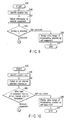
- FIGS. 2, 3 and 4 are flowcharts showing a detail channel preset method for the digital TV broadcast. That is, when the channel preset operation is required by operating the remote controller 17, the operation is started (step S1).
- the controller 16 displays a channel setting screen indicating the present channel preset setting state stored in the memory 19 on the display unit 15 in step S2.
- the channel setting screen displays a table in which the position keys 17c of the remote controller 17, digital broadcast channels, display numbers of the respective channels, and information items (containing an unused case) which specify equipment connected to the network to receive the respective channels are set to correspond to one another.
- a cursor K which surrounds one of the position keys 17c, and a broadcast channel, display number and equipment corresponding thereto is displayed.
- the cursor K is displayed to make the color of a portion surrounded by the frame different from the color of other portions.
- step S3 the controller 16 determines whether or not one of the up key 17d and down key 17e of the remote controller 17 has been operated.
- the controller 16 shifts the cursor K towards the position key 17c side of a smaller number than the present number, that is, in an upward direction in the case of FIG. 5A in step S4.
- the controller 16 shifts the cursor K towards the position key 17c side of a larger number than the present number, that is, in a downward direction in the case of FIG. 5A in step S5.
- the controller 16 determines in step S6 whether or not the enter key 17h of the remote controller 17 is operated.
- the controller 16 displays a setting OSD (On Screen Display) screen as shown in FIG. 5B on the display unit 15 in step S7.
- OSD On Screen Display
- the setting OSD screen shows a state in which the position key 17c having the number "1" attached thereto is selected in step S6. At this time, the present broadcast channel, the display number of the channel and use or nonuse of equipment connected to the network which are set in correspondence to the position key 17c are displayed thereon.
- the controller 16 displays the cursor K on the item of the broadcast channel on the setting OSD screen in step S8. Also, in this case, the cursor K is displayed to make the color of a portion in the frame different from the color of other portions.
- step S9 the controller 16 determines whether or not one of the up key 17d and down key 17e of the remote controller 17 has been operated.
- the controller 16 increments the number of the broadcast channel by adding "+1" to the number displayed at present ("1" in FIG. 5B) in step S10.
- the controller 16 decrements the number of the broadcast channel by subtracting "1" from the number displayed at present ("1" in FIG. 5B) in step S11.
- the controller 16 determines in step S12 whether or not the enter key 17h of the remote controller 17 is operated.
- the controller 16 displays the cursor K on the item of the display number on the setting OSD screen in step S13. Also, in this case, the cursor K is displayed to make the color of a portion in the frame different from the color of other portions.
- step S14 the controller 16 determines whether or not one of the up key 17d and down key 17e of the remote controller 17 has been operated.
- the controller 16 increments the display number by adding "+1" to the number displayed at present ("1" in FIG. 5B) in step S15. Further, if the down key 17e has been operated, the controller 16 decrements the display number by subtracting "1" from the number displayed at present ("1" in FIG. 5B) in step S16.
- the controller 16 determines in step S17 whether or not the enter key 17h of the remote controller 17 is operated.
- the controller 16 displays the cursor K on the item of the network equipment on the setting OSD screen in step S18. Also, in this case, the cursor K is displayed to make the color of a portion in the frame different from the color of other portions.
- step S19 the controller 16 determines whether or not one of the up key 17d and down key 17e of the remote controller 17 has been operated.
- step S20 If the present setting is made to indicate that the network equipment is "unused”, the controller 16 makes a change to "use” in step S20 when either the up key 17d or the down key 17e is operated.
- the controller 16 makes a change to "unused” in step S21 when either the up key 17d or the down key 17e is operated.
- the controller 16 determines in step S22 whether or not the enter key 17h of the remote controller 17 is operated.
- step S23 the controller 16 determines in step S23 whether or not the setting is made to indicate that the network equipment is "used". If "used" is set, the controller 16 displays the setting OSD screen used to set the network equipment to be used on the display unit 15 as shown in FIG. 5C in step S24.
- the setting OSD screen shows an equipment connected to the network as a registered equipment number "1" and the maker name of the equipment, the type name, the power supply state, the form of an output signal, the channel and the like are displayed.
- the controller 16 displays the cursor K on the item of the registered equipment number on the setting OSD screen in step S25. Also, in this case, the cursor K is displayed to make the color of a portion in the frame different from the color of other portions.
- step S26 the controller 16 determines whether or not one of the up key 17d and down key 17e of the remote controller 17 has been operated.
- the controller 16 increments the registered equipment number by adding "+1" to the number displayed at present ("1" in FIG. 5C) in the step S27. Further, if the down key 17e has been operated, the controller 16 decrements the registered equipment number by subtracting "1" from the number displayed at present ("1" in FIG. 5C) in step S28.
- the controller 16 determines in step S29 whether or not the enter key 17h of the remote controller 17 is operated.
- step S30 the controller 16 determines in step S30 whether or not channel information (which will be described later) of a partner equipment is acquired. If the information cannot be acquired, the controller 16 displays a message used to confirm the setting of the partner equipment as shown in FIG. 5D in step S31.
- step S32 determines in step S32 whether or not a key indicating the completion of the process is operated or whether or not the entry key 17h is operated again for retry based on the user determination. If the enter key 17h is operated, the process is returned to step S30.
- the controller 16 stores the set condition, that is, the position key 17c of the remote controller 17, broadcast channel, display number and information related to equipment on the network when the equipment is used which are set to correspond to one another in the memory 19 in step S33. Then, the channel preset operation is terminated (step S34).
- step S23 When the_setting is detected in step S23 to indicate that the network equipment is not “used” or when channel selecting information is acquired in step S30, the controller 16 causes the process to directly proceed to step S33.
- the channel selecting information is information to specify control information which is required to permit the channel selecting operation of the partner equipment to be performed from the network side.
- Equipment having an AV/C command (tuner command) of IEEE 1394 provided thereon is standardized to ARIB (Association of Radio Industries and Businesses) if it is a Japanese digital broadcast receiver and is required to have a channel selecting function carried out by other equipment.
- GUID (a number separated for each unit of 64 bits) used to specify a partner equipment and data (only terrestrial digital data) corresponding to network ID, service ID (in the case of BS/110 degree CS of Japan) and +remote_control_key_id used to perform the channel selecting process are required.
- data can be normally acquired by transferring commands.
- the setting of the network equipment is made after the analog setting.
- this is not limitative and a method for first selecting one of the settings and exclusively using the selected setting can be used.
- FIGS. 6 and 7 show a first example of the channel selecting operation.
- a self-equipment (analog TV receiver 11) is selected and the channel selecting operation is performed when the position key 17c is operated. If the operation cannot be successfully performed, network equipment (digital TV receiver 22) is automatically selected and the channel selecting operation is performed.
- the controller 16 identifies the operated position key 17c in step S36. Then, it causes the self-equipment (analog TV receiver 11) to perform the channel selecting operation based on the table stored in the memory 19 in step S37.
- step S38 determines in step S38 whether or not the carrier of the broadcasting signal is detected.
- the controller 16 determines whether or not a video signal is present in step S39.
- the controller 16 causes the TV broadcasting video signal selected by the self-equipment to be displayed on the display unit 15 as shown in FIG. 8A in step S40 and then terminates the process (step S41).
- the controller 16 determines the presence or absence of an audio signal in step S42. When the audio signal is present, the process proceeds to step S40.
- the controller 16 retrieves specified network equipment (in this case, which is a digital TV receiver 22) based on the table stored in the memory 19 in step S43.
- the retrieving operation is performed by specifying a node number of equipment based on the set GUID.
- the controller 16 determines the presence or absence of the equipment in step S44. If the equipment is not present, the controller 16 causes a message as shown in FIG. 8B to be displayed on the display unit 15 in step S45 and terminates the process (step S46).
- the controller 16 When the equipment is present, the controller 16 performs a process for connection with the equipment in step S47. Then, it determines in step S48 whether or not the connection is successfully made. If the connection fails to be successfully made, the controller 16 causes a message as shown in FIG. 8C to be displayed on the display unit 15 in step S49 and terminates the process (step S50).
- the controller 16 issues a channel selection instruction to the digital TV receiver 22 based on the table stored in the memory 19 in step S51.
- the controller 16 determines whether or not the channel selection is successfully performed in step S52. If the channel selection fails to be successfully performed, the controller 16 causes a message as shown in FIG. 8D to be displayed on the display unit 15 in step S53 and terminates the process (step S54).
- the controller 16 provides a display indicating that the channel selection is performed by the network equipment in step S55 and terminates the process (step S56).
- the analog TV receiver 11 has a function of receiving the broadcasting signal of a channel selected by the digital TV receiver 22 via the serial bus 21 and displaying the same on the display unit 15. Then, "i. LINK" indicating the broadcasting video signal from the network equipment is displayed together with the broadcast channel (CH 1) on the screen of the display unit 15.
- FIG. 9 shows a second example of the channel selecting operation.
- the network equipment digital TV receivers 22
- step S36 the controller 16 acquires information of the network equipment (digital TV receiver 22) based on the table stored in the memory 19 in the step S57.
- step S58 determines in step S58 whether or not setting of the channel preset is made on the network equipment. If no setting is made, the process proceeds to step 540, and if setting is made, the process of step S43 shown in FIG. 7 is performed.
- FIG. 10 shows a third example of the channel selecting operation.
- information indicating which one of the self-equipment and network equipment is preferentially dealt with at the channel selection time is contained in the channel selecting information and registered at the channel preset time. Then, at the time of the channel selecting operation, the equipment having the effective channel selecting information attached thereto is preferentially selected and the channel selecting operation thereof is performed.
- step S36 the controller 16 acquires effective channel selecting information based on the table stored in the memory 19 in step S59.
- the controller 16 determines the equipment having effective channel selecting information in step S60. If the equipment is the self-equipment, the process proceeds to step S40 and if the equipment is the network equipment, the process proceeds to step S43.
- FIG. 11 shows a fourth example of the channel selecting operation.
- the position key 17c is successively operated twice in a preset period of time, the self-equipment is selected and the channel selecting operation is performed. If the position key 17c is operated only once in a preset period of time, the network equipment is selected and' the channel selecting operation is performed.
- step S36 the controller 16 sets a built-in timer for determination of successive operations into an operative state in step S61.
- the controller 16 determines in step S62 whether or not the position key 17c is operated once more, that is, the position key 17c is successively operated twice (or double-clicked). If it is determined that the position key 17c is successively operated twice, the controller 16 determines that the self-equipment is selected and the process proceeds to step S40.
- step S63 determines in step S63 whether or not a preset period of time has elapsed by use of the built-in timer for determination of successive operations. If the elapsed time is within the preset time (No in step S63), the process is returned to step S62.
- step S63 determines that the position key 17c is operated only once in the preset period of time. In this case, the controller 16 determines that network equipment is selected and the process proceeds to the step S43.
- step S62 If it is determined in step S62 that the position key is operated but is not operated twice, the controller 16 interrupts the channel selecting operation in step S64.
- channel selecting information items of the self-equipment and channel selecting information items used to permit other broadcast receivers connected to the network to perform the channel selecting operation via the digital interface which are set to correspond to the keys of the remote controller used to control the self-equipment are stored.
- the channel selecting operation using the channel preset function can be performed with respect to any one of the broadcast receivers.
- easy channel selecting operation based on the channel preset function by using the remote controller of the self-equipment can be realized with respect to other broadcast receivers connected to the network.
- a broadcast receiver apparatus, broadcast receiving method and AV network system can be provided in which an easy channel selecting operation based on the channel preset function by using the remote controller of the self-equipment can be realized with respect to other broadcast receivers connected to the network.
Landscapes
- Engineering & Computer Science (AREA)
- Multimedia (AREA)
- Signal Processing (AREA)
- Human Computer Interaction (AREA)
- Databases & Information Systems (AREA)
- Computer Networks & Wireless Communication (AREA)
- Details Of Television Systems (AREA)
- Circuits Of Receivers In General (AREA)
- Selective Calling Equipment (AREA)
Abstract
A broadcast receiver (22) is connected to a
broadcast receiver (11) via a digital interface.
Information items to select receivable broadcast
channels of the broadcast receiver (11) are stored in
correspondence to position keys (17c) of a remote
controller (17) which controls the broadcast receiver
(11). Further, information items to specify the
broadcast receiver (22) and select receivable broadcast
channels via a digital interface are stored in
correspondence to the position keys (17c). When the
position key (17c) is operated, the broadcast receiver
(11 or 22) is selectively caused to perform the channel
selecting operation based on the stored information.
Description
This invention relates to the improvement of a
broadcast receiver apparatus which is connected to a
digital interface in conformity,to the IEEE (the
Institute of Electrical and Electronics Engineers) 1394
standard, for example, and a broadcast receiving method
and AV network system.
As is well known in the art, recently, it is
possible to configure a network system in which a
plurality of pieces of AV equipment are connected to
one another in a desired form by use of a serial bus
using a digital interface in conformity to the IEEE
1394 standard.
In this type of network system, a specified piece
of AV equipment having an image display function can be
used to freely and selectively specify another piece of
AV equipment and control the operation thereof.
However, in this case, it becomes necessary to
display a selection screen of the other piece of AV
equipment connected to the network on the screen of the
specified piece of AV equipment and then the operation
of selecting one of the piece of AV equipment to be
controlled is performed.
After this, it becomes necessary to perform two-step
operations of displaying an operation screen for
controlling the selected piece of AV equipment on the
screen of the specified piece of AV equipment and
performing an operation of selecting desired control
contents. Thus, the equipment becomes inconvenient to
handle.
In a television broadcast (TV) receiver, a so-called
channel preset function of allocating a
plurality of broadcast channels to a plurality of
position keys set on a remote controller is provided.
Simply by operating a desired position key, a
broadcast channel allocated to the position key can be
automatically selected according to the channel preset
function. Thus, it becomes convenient to handle the
equipment.
For example, in Jpn. Pat. Appln. KOKAI Publication
No. 11-32262 proposed as Patent Document 1, a channel
preset device for separately displaying all of
receivable channels and making a preset setting based
on the separate display screen is disclosed.
In the field of TV broadcasting, TV broadcasting
will be changed from the terrestrial analog broadcasting
to terrestrial digital broadcasting in the
future. In order to watch (view and listen to) a
'terrestrial digital broadcast, a TV receiver which can
cope with the terrestrial digital broadcast is
required.
Therefore, in a transition period from terrestrial
analog broadcasting to terrestrial digital broadcasting,
TV receivers which can cope with the present
terrestrial analog broadcasts and TV receivers which
can cope with terrestrial digital broadcasts are used
together.
In this case, it is considered that a network
coping with the IEEE 1394 standard can be configured by
using TV receivers which can cope with the present
terrestrial analog broadcasting as specified equipment
and using TV receivers which can cope with terrestrial
digital broadcasting as other equipment.
However, in the above network configuration, when
the receiver for the terrestrial analog broadcast
controls the receiver for the terrestrial digital
broadcast, two-step operations are required as
described above and it becomes inconvenient to handle
the equipment.
Further, when the channel preset function is used,
receivable channels of the receiver for the terrestrial
analog broadcast are set on the remote controller of
the receiver for the terrestrial analog broadcast and
the channel selecting operation is performed by use of
the remote controller.
Further, in the TV receiver which can cope with
terrestrial digital broadcasts, a desired broadcast
channel is selected from a large number of broadcast
channels by operating the exclusive remote controller
thereof.
That is, the channel selecting operation of the
receiver for the terrestrial digital broadcast is
performed by use of the receiver for the terrestrial
analog broadcast by performing the two-step troublesome
operations via the network. Alternatively, the channel
selecting operation is performed by use of the
exclusive remote controller.
Further, in Jpn. Pat. Appln. KOKAI Publication
No. 2002-223482 proposed as Patent Document 2, the
configuration for controlling a to-be-controlled device
connected to a controller via a network by controlling
the controller by use of a remote controller is
disclosed.
In addition, in Jpn. Pat. Appln. KOKAI Publication
No. 2002-112367 proposed as Patent Document 3, the
configuration in which the operating device determines
a plurality of pieces of control equipment of the same
type connected via the network and selectively controls
the same is disclosed.
However, in neither of the above Patent
Documents 2 and 3 is the technique for simplifying the
selecting operation for both of the TV receivers
described at all.
This invention has been made to solve the above
problem and an object of this invention is to provide a
broadcast receiver apparatus which can realize an easy
channel selecting operation based on the preset channel
function by use of its own remote controller with
respect to other broadcast receivers connected to a
network, and a broadcast receiving method and AV
network system.
A broadcast receiver apparatus according to an
aspect of the present invention comprises connection
means for connection with an external broadcast
receiver via a digital interface to control the same,
and preset means for storing information items which
are used to select receivable broadcast channels
thereof and set to correspond to a plurality of keys
and storing information items which are used to specify
the external broadcast receiver, select broadcast
channels which can be received by the external
broadcast receiver via the digital interface and set to
correspond to the plurality of keys.
Further, a broadcast receiving method according to
another aspect of the present invention comprises
storing information items used to select broadcast
channels which can be received by a self-equipment and
set to correspond to a plurality of keys provided on a
remote controller to control the self-equipment, and
storing information items which specify an external
broadcast receiver connected via a digital interface to
be controlled, cause the external broadcast receiver to
select broadcast channels which can be received via the
digital interface and are set to correspond to the
plurality of keys provided on the remote controller.
In addition, an AV network system according to
still another aspect of the present invention has first
and second broadcast receivers connected to each other
via a digital interface, the second broadcast receiver
being controlled by the first broadcast receiver.
Further, it comprises preset means for storing
information items which are used to select broadcast
channels which can be received by the first broadcast
receiver and set to correspond to a plurality of keys
provided on a remote controller to control the first
broadcast receiver and storing information items which
specify the second broadcast receiver, select broadcast
channels which can be received by the second broadcast
receiver via the digital interface and are set to
correspond to the plurality of keys provided on the
remote controller, identifying means for identifying an
operated key among the plurality of keys provided on
the remote controller, and channel selecting means for
selectively causing one of the first and second
broadcast receivers to perform the channel selecting
operation based on the information stored by the preset
means in correspondence to the key identified by the
identifying means.
This summary of the invention does not necessarily
describe all necessary features so that the invention
may also be a sub-combination of these described
features.
The invention can be more fully understood from
the following detailed description when taken in
conjunction with the accompanying drawings, in which:
There will now be described an embodiment of this
invention in detail with reference to the accompanying
drawings. FIG. 1 schematically shows a network system
explained in the present embodiment. That is, in
FIG. 1, a symbol 11 denotes a terrestrial analog
television broadcast (TV) receiver which receives a
terrestrial analog TV broadcast.
In the analog TV receiver 11, the analog TV
broadcasting signal received by an antenna 12 is
supplied to a tuner 13 and a TV signal of a preset
broadcast channel is selected.
Then, after the TV signal selected by the tuner 13
is supplied to and demodulated by an image processor
14, it is supplied to and displayed on a display unit
15. Thus, the received analog TV broadcast is
reproduced.
A series of reproduction operations described
above is collectively controlled by a controller 16
containing a microcomputer or the like. The controller
16 is supplied with operation information from a remote
controller 17 via an optical receiver 18.
The controller 16 controls the tuner 13 and image
processor 14 to reflect operation information from the
remote controller 17 based on a control program stored
in a memory 19.
The memory 19 provides a working area of the
controller 16 and, for example, stores various types of
setting data items such as a table indicating the
correspondence relation between broadcast channels and
keys of the remote controller 17 set by use of the
channel preset function.
A power supply key 17a, various control keys 17b
to control the analog TV receiver 11, position keys 17c
and the like are provided on the remote controller 17.
The position keys 17c are set to correspond to the
broadcast channels by the channel preset function.
Further, an up key 17d, down key 17e, left key
17f, right key 17g to move a cursor displayed on the
display unit 15 in up, down, right and left directions,
an enter key 17h to determine an item specified by
the cursor and the like are provided on the remote
controller 17.
An input/output port 20 having a digital interface
function and coping with the IEEE 1394 standard is
connected to the controller 16. The input/output port
20 is connected to a digital TV receiver 22 coping with
the terrestrial digital TV broadcast and having a
digital interface function in conformity to the IEEE
1394 standard via a serial bus [i. LINK (registered
trademark) cable] 21. Thus, a network system is
configured.
With the above configuration, the controller 16
transmits operation information for the digital TV
receiver 22 input via the remote controller 17 to the
digital TV receiver 22 via the input/output port 20 and
serial bus 21 as an AV (Audio Video)/C (control)
command. Thus, the digital TV receiver 22 can be
controlled.
The controller 16 can realize a channel preset
function by setting the broadcast channels of the
analog TV broadcast to correspond to the position keys
17c of the remote controller 17 and storing a table
indicating the correspondence relation therebetween in
the memory 19 by operating the remote controller 17.
The controller 16 controls the tuner to select
an analog TV broadcast channel corresponding to an
operated one of the position keys 17c by selectively
operating the position key 17c of the remote controller
17. Thus, the channel selecting operation by the
channel preset function is performed.
Further, the controller 16 can realize a channel
preset function for the digital TV broadcast by setting
broadcast channels of the digital TV broadcast which
can be received by the digital TV receiver 22 to
correspond to the position keys 17c of the remote
controller 17 and storing a table indicting the
correspondence relation therebetween in the memory 19.
In this case, the controller 16 sets the position
keys 17c of the remote controller 17, the broadcast
channels of the digital TV broadcast and information
which specifies a digital TV receiver 22 connected to
the network via the serial bus 21 to correspond to one
another. Further, it stores a table indicating the
correspondence relation between them in the memory 19.
When one of the position keys 17c of the remote
controller 17 is selectively operated, the controller
16 transmits the AV/C command to a digital TV receiver
22 corresponding to the operated position key 17c to
select a digital TV broadcast channel corresponding to
the operated position key 17c. Thus, the channel
selecting operation by the channel preset function is
performed.
FIGS. 2, 3 and 4 are flowcharts showing a detail
channel preset method for the digital TV broadcast.
That is, when the channel preset operation is required
by operating the remote controller 17, the operation is
started (step S1).
Then, the controller 16 displays a channel setting
screen indicating the present channel preset setting
state stored in the memory 19 on the display unit 15 in
step S2.
As shown in FIG. 5A, the channel setting screen
displays a table in which the position keys 17c of the
remote controller 17, digital broadcast channels,
display numbers of the respective channels, and
information items (containing an unused case) which
specify equipment connected to the network to receive
the respective channels are set to correspond to one
another.
On the channel setting screen, a cursor K which
surrounds one of the position keys 17c, and a broadcast
channel, display number and equipment corresponding
thereto is displayed. The cursor K is displayed to
make the color of a portion surrounded by the frame
different from the color of other portions.
Next, in step S3, the controller 16 determines
whether or not one of the up key 17d and down key 17e
of the remote controller 17 has been operated.
If the up key 17d has been operated, the
controller 16 shifts the cursor K towards the position
key 17c side of a smaller number than the present
number, that is, in an upward direction in the case of
FIG. 5A in step S4.
Further, if the down key 17e has been operated,
the controller 16 shifts the cursor K towards the
position key 17c side of a larger number than the
present number, that is, in a downward direction in the
case of FIG. 5A in step S5.
If none of the keys 17d and 17e is operated, the
controller 16 determines in step S6 whether or not the
enter key 17h of the remote controller 17 is operated.
If the enter key 17h is operated, the controller
16 displays a setting OSD (On Screen Display) screen as
shown in FIG. 5B on the display unit 15 in step S7.
The setting OSD screen shows a state in which the
position key 17c having the number "1" attached thereto
is selected in step S6. At this time, the present
broadcast channel, the display number of the channel
and use or nonuse of equipment connected to the network
which are set in correspondence to the position key 17c
are displayed thereon.
After this, the controller 16 displays the cursor
K on the item of the broadcast channel on the setting
OSD screen in step S8. Also, in this case, the cursor
K is displayed to make the color of a portion in the
frame different from the color of other portions.
Next, in step S9, the controller 16 determines
whether or not one of the up key 17d and down key 17e
of the remote controller 17 has been operated.
If the up key 17d has been operated, the
controller 16 increments the number of the broadcast
channel by adding "+1" to the number displayed at
present ("1" in FIG. 5B) in step S10.
Further, if the down key 17e has been operated,
the controller 16 decrements the number of the
broadcast channel by subtracting "1" from the number
displayed at present ("1" in FIG. 5B) in step S11.
If none of the keys 17d and 17e is operated, the
controller 16 determines in step S12 whether or not the
enter key 17h of the remote controller 17 is operated.
If the enter key 17h is operated, the controller
16 displays the cursor K on the item of the display
number on the setting OSD screen in step S13. Also, in
this case, the cursor K is displayed to make the color
of a portion in the frame different from the color of
other portions.
Then, in step S14, the controller 16 determines
whether or not one of the up key 17d and down key 17e
of the remote controller 17 has been operated.
If the up key 17d has been operated, the
controller 16 increments the display number by adding
"+1" to the number displayed at present ("1" in
FIG. 5B) in step S15. Further, if the down key 17e has
been operated, the controller 16 decrements the display
number by subtracting "1" from the number displayed at
present ("1" in FIG. 5B) in step S16.
If none of the keys 17d and 17e is operated, the
controller 16 determines in step S17 whether or not the
enter key 17h of the remote controller 17 is operated.
If the enter key 17h is operated, the controller
16 displays the cursor K on the item of the network
equipment on the setting OSD screen in step S18. Also,
in this case, the cursor K is displayed to make the
color of a portion in the frame different from the
color of other portions.
Then, in step S19, the controller 16 determines
whether or not one of the up key 17d and down key 17e
of the remote controller 17 has been operated.
If the present setting is made to indicate that
the network equipment is "unused", the controller 16
makes a change to "use" in step S20 when either the up
key 17d or the down key 17e is operated.
If the present setting is made to indicate that
the network equipment is "used", the controller 16
makes a change to "unused" in step S21 when either the
up key 17d or the down key 17e is operated.
If none of the keys 17d and 17e is operated, the
controller 16 determines in step S22 whether or not the
enter key 17h of the remote controller 17 is operated.
If the enter key 17h is operated, the controller
16 determines in step S23 whether or not the setting is
made to indicate that the network equipment is "used".
If "used" is set, the controller 16 displays the
setting OSD screen used to set the network equipment to
be used on the display unit 15 as shown in FIG. 5C in
step S24.
The setting OSD screen shows an equipment
connected to the network as a registered equipment
number "1" and the maker name of the equipment, the
type name, the power supply state, the form of an
output signal, the channel and the like are displayed.
After this, the controller 16 displays the cursor
K on the item of the registered equipment number on the
setting OSD screen in step S25. Also, in this case,
the cursor K is displayed to make the color of a
portion in the frame different from the color of other
portions.
Then, in step S26, the controller 16 determines
whether or not one of the up key 17d and down key 17e
of the remote controller 17 has been operated.
If the up key 17d has been operated, the
controller 16 increments the registered equipment
number by adding "+1" to the number displayed at
present ("1" in FIG. 5C) in the step S27. Further, if
the down key 17e has been operated, the controller 16
decrements the registered equipment number by
subtracting "1" from the number displayed at present
("1" in FIG. 5C) in step S28.
If none of the keys 17d and 17e is operated, the
controller 16 determines in step S29 whether or not the
enter key 17h of the remote controller 17 is operated.
If the enter key 17h is operated, the controller
16 determines in step S30 whether or not channel
information (which will be described later) of a
partner equipment is acquired. If the information
cannot be acquired, the controller 16 displays a
message used to confirm the setting of the partner
equipment as shown in FIG. 5D in step S31.
After this, the controller 16 determines in step
S32 whether or not a key indicating the completion of
the process is operated or whether or not the entry key
17h is operated again for retry based on the user
determination. If the enter key 17h is operated, the
process is returned to step S30.
Further, if the key indicating the completion of
the process is operated, the controller 16 stores the
set condition, that is, the position key 17c of the
remote controller 17, broadcast channel, display number
and information related to equipment on the network
when the equipment is used which are set to correspond
to one another in the memory 19 in step S33. Then, the
channel preset operation is terminated (step S34).
When the_setting is detected in step S23 to
indicate that the network equipment is not "used" or
when channel selecting information is acquired in step
S30, the controller 16 causes the process to directly
proceed to step S33.
The channel selecting information is information
to specify control information which is required to
permit the channel selecting operation of the partner
equipment to be performed from the network side.
Equipment having an AV/C command (tuner command) of
IEEE 1394 provided thereon is standardized to ARIB
(Association of Radio Industries and Businesses) if it
is a Japanese digital broadcast receiver and is
required to have a channel selecting function carried
out by other equipment.
As concrete items, GUID (a number separated for
each unit of 64 bits) used to specify a partner
equipment and data (only terrestrial digital data)
corresponding to network ID, service ID (in the case of
BS/110 degree CS of Japan) and +remote_control_key_id
used to perform the channel selecting process are
required. In the case of equipment connected to the
IEEE 1394 bus, data can be normally acquired by
transferring commands.
A case wherein the tuner is used is explained.
However, recently, an environment in which a device is
used other than the tuner and can be dealt with in the
same manner as an external tuner by increasing the
capacity of a storage medium and stimulating the server
function thereof is being provided. Therefore,
operation which is not limited to the tuner can be
performed.
In the channel preset procedure, the setting of
the network equipment is made after the analog setting.
However, this is not limitative and a method for first
selecting one of the settings and exclusively using the
selected setting can be used.
Next, the operation for operating the remote
controller 17 to select the channel in a state in which
the channel preset process is performed as described
above is explained. FIGS. 6 and 7 show a first example
of the channel selecting operation.
In the first example, first, a self-equipment
(analog TV receiver 11) is selected and the channel
selecting operation is performed when the position
key 17c is operated. If the operation cannot be
successfully performed, network equipment (digital TV
receiver 22) is automatically selected and the channel
selecting operation is performed.
That is, when the position key 17c of the remote
controller 17 is selectively operated and the channel
selecting operation is started (step S35), the
controller 16 identifies the operated position key 17c
in step S36. Then, it causes the self-equipment
(analog TV receiver 11) to perform the channel
selecting operation based on the table stored in the
memory 19 in step S37.
Further, the controller 16 determines in step S38
whether or not the carrier of the broadcasting signal
is detected. When the presence of the carrier is
uncertain or the carrier is detected, the controller 16
determines whether or not a video signal is present in
step S39.
When the video signal is detected, the controller
16 causes the TV broadcasting video signal selected by
the self-equipment to be displayed on the display unit
15 as shown in FIG. 8A in step S40 and then terminates
the process (step S41).
When the presence or absence of the video signal
is uncertain, the controller 16 determines the presence
or absence of an audio signal in step S42. When the
audio signal is present, the process proceeds to
step S40.
When the presence or absence of the audio signal
is uncertain or it is determined that at least.one of
the carrier, video signal and audio signal is not
present, the controller 16 retrieves specified network
equipment (in this case, which is a digital TV receiver
22) based on the table stored in the memory 19 in step
S43. The retrieving operation is performed by
specifying a node number of equipment based on the set
GUID.
Then, the controller 16 determines the presence or
absence of the equipment in step S44. If the equipment
is not present, the controller 16 causes a message as
shown in FIG. 8B to be displayed on the display unit 15
in step S45 and terminates the process (step S46).
When the equipment is present, the controller 16
performs a process for connection with the equipment in
step S47. Then, it determines in step S48 whether or
not the connection is successfully made. If the
connection fails to be successfully made, the
controller 16 causes a message as shown in FIG. 8C to
be displayed on the display unit 15 in step S49 and
terminates the process (step S50).
When the connection is successfully made, the
controller 16 issues a channel selection instruction to
the digital TV receiver 22 based on the table stored in
the memory 19 in step S51.
Then, the controller 16 determines whether or not
the channel selection is successfully performed in step
S52. If the channel selection fails to be successfully
performed, the controller 16 causes a message as shown
in FIG. 8D to be displayed on the display unit 15 in
step S53 and terminates the process (step S54).
Further, when the channel selection is
successfully performed, the controller 16 provides a
display indicating that the channel selection is
performed by the network equipment in step S55 and
terminates the process (step S56).
In this case, the analog TV receiver 11 has a
function of receiving the broadcasting signal of a
channel selected by the digital TV receiver 22 via the
serial bus 21 and displaying the same on the display
unit 15. Then, "i. LINK" indicating the broadcasting
video signal from the network equipment is displayed
together with the broadcast channel (CH 1) on the
screen of the display unit 15.
FIG. 9 shows a second example of the channel
selecting operation. In the second example, when one
of the position keys 17c on which the network equipment
(digital TV receivers 22) are registered is operated,
first, the network equipment is preferentially selected
and the channel selecting operation is performed.
In the following explanation, the same symbols are
attached to the same steps as those in FIG. 6. When
the operated position key 17c is identified in step
S36, the controller 16 acquires information of the
network equipment (digital TV receiver 22) based on the
table stored in the memory 19 in the step S57.
After this, the controller 16 determines in step
S58 whether or not setting of the channel preset is
made on the network equipment. If no setting is made,
the process proceeds to step 540, and if setting is
made, the process of step S43 shown in FIG. 7 is
performed.
FIG. 10 shows a third example of the channel
selecting operation. In the third example, information
indicating which one of the self-equipment and network
equipment is preferentially dealt with at the channel
selection time is contained in the channel selecting
information and registered at the channel preset time.
Then, at the time of the channel selecting operation,
the equipment having the effective channel selecting
information attached thereto is preferentially selected
and the channel selecting operation thereof is
performed.
In the following explanation, the same symbols are
attached to the same steps as those in FIG. 6. When
the operated position key 17c is identified in step
S36, the controller 16 acquires effective channel
selecting information based on the table stored in the
memory 19 in step S59.
The controller 16 determines the equipment having
effective channel selecting information in step S60.
If the equipment is the self-equipment, the process
proceeds to step S40 and if the equipment is the
network equipment, the process proceeds to step S43.
FIG. 11 shows a fourth example of the channel
selecting operation. In the fourth example, if the
position key 17c is successively operated twice in a
preset period of time, the self-equipment is selected
and the channel selecting operation is performed. If
the position key 17c is operated only once in a preset
period of time, the network equipment is selected and'
the channel selecting operation is performed.
In the following explanation, the same symbols are
attached to the same steps as those in FIG. 6. When
the operated position key 17c is identified in step
S36, the controller 16 sets a built-in timer for
determination of successive operations into an
operative state in step S61.
The controller 16 determines in step S62 whether
or not the position key 17c is operated once more, that
is, the position key 17c is successively operated twice
(or double-clicked). If it is determined that the
position key 17c is successively operated twice, the
controller 16 determines that the self-equipment is
selected and the process proceeds to step S40.
If none of the position keys 17c is operated, the
controller 16 determines in step S63 whether or not a
preset period of time has elapsed by use of the built-in
timer for determination of successive operations.
If the elapsed time is within the preset time (No in
step S63), the process is returned to step S62.
Further, when a preset period of time has elapsed
(Yes in step S63), the controller 16 determines that
the position key 17c is operated only once in the
preset period of time. In this case, the controller 16
determines that network equipment is selected and the
process proceeds to the step S43.
If it is determined in step S62 that the position
key is operated but is not operated twice, the
controller 16 interrupts the channel selecting
operation in step S64.
According to the above configuration, method and
system, channel selecting information items of the
self-equipment and channel selecting information items
used to permit other broadcast receivers connected to
the network to perform the channel selecting operation
via the digital interface which are set to correspond
to the keys of the remote controller used to control
the self-equipment are stored.
Therefore, simply by operating the key of the
remote controller, the channel selecting operation
using the channel preset function can be performed with
respect to any one of the broadcast receivers. Thus,
easy channel selecting operation based on the channel
preset function by using the remote controller of the
self-equipment can be realized with respect to other
broadcast receivers connected to the network.
As described above, according to this invention, a
broadcast receiver apparatus, broadcast receiving
method and AV network system can be provided in which
an easy channel selecting operation based on the
channel preset function by using the remote controller
of the self-equipment can be realized with respect to
other broadcast receivers connected to the network.
Claims (17)
- A broadcast receiver apparatus (11, 17 in FIG. 1) characterized by comprising:a connection unit (16, 20) configured to be connected to an external broadcast receiver (22) via a digital interface (20), said external broadcast receiver (22) being controllable via said digital interface (20); anda preset unit (16, 17, 19) configured to store first information and second information, whereinsaid first information serves to link first selection information of channels (analog broadcast channels) being receivable by the broadcast receiver apparatus (11), with first prescribed keys (17b), andsaid second information serves to specify said external broadcast receiver (22) and to link second selection information of channels (digital broadcast channels) to be received by said external broadcast receiver (22), with second prescribed keys (17c).
- The apparatus of claim 1, characterized in that said first and second prescribed keys (17b, 17c) are provided on a remote controller (17) for use with the broadcast receiver apparatus (11).
- The apparatus of claim 1, characterized in that said preset unit includesa first selector (16 in FIG. 1; S2-S6 in FIG. 2) configured to select one or more keys (position keys of S1, S5) from the first or second prescribed keys;a second selector (16 in FIG. 1; S7-S12, S13-S17 in FIG. 3) configured to select one or more broadcast channels to be linked with the one or more keys selected by said first selector;a third selector (16 in FIG. 1; S18-S23 in FIG. 3) configured to select eitherusing said external broadcast receiver (22) to receive the broadcast channel selected by said second selector, orunusing said external broadcast receiver (22), anda fourth selector (16 in FIG. 1; S24 in FIG. 3 to S32 in FIG. 4) configured to select said external broadcast receiver (22) to be used according to the selection of said third selector.
- The apparatus of claim 3, characterized in that said broadcast receiver apparatus (11) is provided with a display unit (15) and is configured to be used with a remote controller (17) having keys (17a-17h) including said first and second prescribed keys (17b, 17c), and
said first to fourth selectors are configured to select one or more items (desired or required by a user) from a setting screen (FIG. 5A-5D) displayed on said display unit (15). - The apparatus of claim 1, characterized by further comprisinga key operation detector (16 in FIG. 1; S36 in FIG. 6) configured to detect an operated key from said first and second prescribed keys (17b, 17c), anda channel selector (16, 17 in FIG. 1; S37 in FIG. 6 to S55 in FIG. 7) configured to selectively activate one of said broadcast receiver apparatus (11) and said external broadcast receiver (22) such that the selectively activated one (11 or 22) performs a channel selection according to the first or second information stored by said preset unit (16, 17, 19).
- The apparatus of claim 5, characterized in that said channel selector (16, 17) is configured to perform a channel selection (S37 in FIG. 6) of the broadcast receiver apparatus (11), and, if the channel selection fails (not-detected at S38, S39, S42 in FIG. 6), said external broadcast receiver (22) is configured to perform another channel selection (S43-S55 in FIG. 7).
- The apparatus of claim 6, characterized in that the failure of the channel selection of said broadcast receiver apparatus (11) is determined by detecting one ofa non-carrier of the selected channel (not-detected at S38 in FIG. 6),a non-video signal of the selected channel (not-detected at S39 in FIG. 6), anda non-audio signal of the selected channel (not-detected at S42 in FIG. 6).
- The apparatus of claim 5, characterized in that a channel selection of the external broadcast receiver (22) has a priority higher than that of the broadcast receiver apparatus (11) when the key, detected by said key operation detector (16, 19), is linked with information for selecting a broadcast channel by said external broadcast receiver (22).
- The apparatus of claim 5, characterized in that said channel selector (16, 17) selectively activates one of said broadcast receiver apparatus (11) and said external broadcast receiver (22) according to setting information (S58 in FIG. 9) stored in the preset unit (16, 17, 19), said setting information stored in the preset unit (16, 17, 19) indicating which of the broadcast receiver apparatus (11) and the external broadcast receiver (22) is to be used for the channel selection.
- The apparatus of claim 5, characterized in that said channel selector (16, 17) selectively activates one of said broadcast receiver apparatus (11) and said external broadcast receiver (22) according to a number of times of operating the key (twice at S62 in FIG. 11; double-clicked), detected by said key operation detector (16, 19), within a predetermined period of time (S63 in FIG. 11).
- A broadcast receiving method (FIGS. 2-4) characterized by comprising:a first process (S1-S17, S33) for storing first information of channels (analog broadcast channels) being receivable by a primary broadcast receiver (11), said first information being obtained by linking the receivable channels with prescribed keys (17b) contained in keys (17a-17h) of a remote controller (17) provided for controlling the primary broadcast receiver (11), anda second process (S18-S33) for storing second information of channels (digital broadcast channels) to be received by an external broadcast receiver (22) which is connected via a digital interface (20) to the primary broadcast receiver (11) such that the external broadcast receiver (22) can be controlled via said digital interface (20), whereinsaid second information serves to specify said external broadcast receiver (22) and to link information for selecting channels (digital broadcast channels) being receivable via said digital interface (20) by said external broadcast receiver (22), with other prescribed keys (17c) contained in the keys (17a-17h) of said remote controller (17).
- The apparatus of claim 11, characterized by further comprising:detecting (S36 in FIG. 6) an operated key from the keys (17a-17h) of said remote controller (17), andselectively activating (S37-S40 in FIG. 6, S43-S55 in FIG. 7) one of said primary and external broadcast receivers (11, 22) such that the selectively activated one (11 or 22) performs a channel selection according to the information stored by said preset unit (16, 17, 19).
- The apparatus of claim 12, characterized by further comprising:performing a channel selection (S37 in FIG. 6) of the primary broadcast receiver (11), and, if the channel selection fails (not-detected at S38, S39, S42 in FIG. 6), performing another channel selection (S43-S55 in FIG. 7) by said external broadcast receiver (22).
- The apparatus of claim 12, characterized in that a channel selection of the external broadcast receiver (22) has a priority higher than that of the primary broadcast receiver (11) when the detected key is linked with information for selecting a broadcast channel by said external broadcast receiver (22).
- The apparatus of claim 12, characterized by further comprising:selectively activating one of said primary and external broadcast receivers (11, 22) according to setting information (S58 in FIG. 9) indicating which of the primary broadcast receiver (11) and the external broadcast receiver (22) is to be used for the channel selection.
- The apparatus of claim 12, characterized by further comprising:selectively activating one of said primary and external broadcast receivers (11, 22) according to a number of times of operating the key (twice at S62 in FIG. 11; double-clicked) within a predetermined period of time (S63 in FIG. 11).
- An AV network system (FIG. 1) in which a first broadcast receiver (11) is connected to a second broadcast receiver (22) via a digital interface (20) so that said second broadcast receiver (22) can be controlled by said first broadcast receiver (11), and wherein said first broadcast receiver (11) is provided with a remote controller (17) having a plurality of keys (17a-17h), said system comprising:a preset unit (16, 17, 19) configured to store first information and second information, whereinsaid first information serves to link first selection information of channels (analog broadcast channels) being receivable by said first broadcast receiver (11), with first prescribed keys (17b) contained in the keys (17a-17h) of said remote controller (17), andsaid second information serves to specify said second broadcast receiver (22) and to link second selection information of channels (digital broadcast channels) to be received by said second broadcast receiver (22), with second prescribed keys (17c) contained in the keys (17a-17h) of said remote controller (17),a key operation detector (16, 19) configured to detect an operated key from the keys (17a-17h) of said remote controller (17), anda channel selector (16, 17) configured to selectively activate one of said first and second broadcast receivers (11, 22) such that the selectively activated one (11 or 22) performs a channel selection according to the information stored by said preset unit (16, 17, 19).
Applications Claiming Priority (2)
| Application Number | Priority Date | Filing Date | Title |
|---|---|---|---|
| JP2002348302 | 2002-11-29 | ||
| JP2002348302A JP2004186768A (en) | 2002-11-29 | 2002-11-29 | Broadcast receiving apparatus, broadcast receiving method, and AV network system |
Publications (1)
| Publication Number | Publication Date |
|---|---|
| EP1424666A2 true EP1424666A2 (en) | 2004-06-02 |
Family
ID=32290500
Family Applications (1)
| Application Number | Title | Priority Date | Filing Date |
|---|---|---|---|
| EP03019847A Withdrawn EP1424666A2 (en) | 2002-11-29 | 2003-09-01 | Broadcast receiver apparatus, broadcast receiving method and AV network system |
Country Status (4)
| Country | Link |
|---|---|
| US (1) | US20040095515A1 (en) |
| EP (1) | EP1424666A2 (en) |
| JP (1) | JP2004186768A (en) |
| CN (1) | CN1505390A (en) |
Families Citing this family (10)
| Publication number | Priority date | Publication date | Assignee | Title |
|---|---|---|---|---|
| US8077679B2 (en) | 2001-03-28 | 2011-12-13 | Qualcomm Incorporated | Method and apparatus for providing protocol options in a wireless communication system |
| US8121296B2 (en) | 2001-03-28 | 2012-02-21 | Qualcomm Incorporated | Method and apparatus for security in a data processing system |
| US9100457B2 (en) | 2001-03-28 | 2015-08-04 | Qualcomm Incorporated | Method and apparatus for transmission framing in a wireless communication system |
| US7352868B2 (en) | 2001-10-09 | 2008-04-01 | Philip Hawkes | Method and apparatus for security in a data processing system |
| US7649829B2 (en) | 2001-10-12 | 2010-01-19 | Qualcomm Incorporated | Method and system for reduction of decoding complexity in a communication system |
| US7599655B2 (en) * | 2003-01-02 | 2009-10-06 | Qualcomm Incorporated | Method and apparatus for broadcast services in a communication system |
| US8098818B2 (en) | 2003-07-07 | 2012-01-17 | Qualcomm Incorporated | Secure registration for a multicast-broadcast-multimedia system (MBMS) |
| US8718279B2 (en) | 2003-07-08 | 2014-05-06 | Qualcomm Incorporated | Apparatus and method for a secure broadcast system |
| US8724803B2 (en) | 2003-09-02 | 2014-05-13 | Qualcomm Incorporated | Method and apparatus for providing authenticated challenges for broadcast-multicast communications in a communication system |
| KR100686093B1 (en) | 2005-02-03 | 2007-02-23 | 엘지전자 주식회사 | Video device and its channel operation method |
-
2002
- 2002-11-29 JP JP2002348302A patent/JP2004186768A/en active Pending
-
2003
- 2003-09-01 EP EP03019847A patent/EP1424666A2/en not_active Withdrawn
- 2003-10-06 US US10/678,311 patent/US20040095515A1/en not_active Abandoned
- 2003-11-27 CN CNA200310118649A patent/CN1505390A/en active Pending
Also Published As
| Publication number | Publication date |
|---|---|
| JP2004186768A (en) | 2004-07-02 |
| CN1505390A (en) | 2004-06-16 |
| US20040095515A1 (en) | 2004-05-20 |
Similar Documents
| Publication | Publication Date | Title |
|---|---|---|
| EP0536901B2 (en) | Display apparatus displaying operation menu | |
| EP0644689B1 (en) | Television set | |
| EP0821856B2 (en) | Merging multi-source information in a television system | |
| US7162733B2 (en) | Method and apparatus for automatic set-up of electronic devices | |
| US6204885B1 (en) | Method and apparatus for displaying textual or graphic data on the screen of television receivers | |
| JP3951158B2 (en) | Remote control device | |
| KR100739405B1 (en) | Method and apparatus for providing feedback during programming of television device | |
| US7051353B2 (en) | Program guide display controller and television receiver | |
| EP0821523B1 (en) | Digital television signal receiver | |
| US6031580A (en) | Apparatus and method for automatically displaying broadcasting program information in television receiver | |
| US20040095515A1 (en) | Broadcast receiver apparatus, broadcast receiving method and AV network system | |
| JP2000197162A (en) | Remote control device | |
| US20070283389A1 (en) | Method and system for helping operate a media-playing set | |
| JP2924610B2 (en) | Television receiver | |
| JP4551631B2 (en) | Program recording reservation method and program recording reservation device | |
| JP4228787B2 (en) | Recording method and apparatus | |
| JP2004363930A (en) | Television broadcast receiving system, remote control device, and program information display method | |
| KR100331801B1 (en) | Method for guidance of installing TV | |
| JP3852422B2 (en) | Reservation setting method and reservation setting device | |
| EP1095513B1 (en) | Method for driving a satellite receiver | |
| EP1641258A1 (en) | Video recording control device and video recording control method | |
| EP0675650A1 (en) | A television receiver with teletext function | |
| JP4314895B2 (en) | Program data processing method and apparatus | |
| KR100675454B1 (en) | Device and setting method of reservation recording using mobile communication terminal | |
| JP2004336693A (en) | Broadcast program recording method and apparatus |
Legal Events
| Date | Code | Title | Description |
|---|---|---|---|
| PUAI | Public reference made under article 153(3) epc to a published international application that has entered the european phase |
Free format text: ORIGINAL CODE: 0009012 |
|
| 17P | Request for examination filed |
Effective date: 20030901 |
|
| AK | Designated contracting states |
Kind code of ref document: A2 Designated state(s): AT BE BG CH CY CZ DE DK EE ES FI FR GB GR HU IE IT LI LU MC NL PT RO SE SI SK TR |
|
| AX | Request for extension of the european patent |
Extension state: AL LT LV MK |
|
| STAA | Information on the status of an ep patent application or granted ep patent |
Free format text: STATUS: THE APPLICATION HAS BEEN WITHDRAWN |
|
| 18W | Application withdrawn |
Effective date: 20060116 |