EP1424476A1 - Fuel injection method - Google Patents
Fuel injection method Download PDFInfo
- Publication number
- EP1424476A1 EP1424476A1 EP02751804A EP02751804A EP1424476A1 EP 1424476 A1 EP1424476 A1 EP 1424476A1 EP 02751804 A EP02751804 A EP 02751804A EP 02751804 A EP02751804 A EP 02751804A EP 1424476 A1 EP1424476 A1 EP 1424476A1
- Authority
- EP
- European Patent Office
- Prior art keywords
- fuel injection
- value
- solenoid
- driving
- coil current
- Prior art date
- Legal status (The legal status is an assumption and is not a legal conclusion. Google has not performed a legal analysis and makes no representation as to the accuracy of the status listed.)
- Withdrawn
Links
Images








Classifications
-
- F—MECHANICAL ENGINEERING; LIGHTING; HEATING; WEAPONS; BLASTING
- F02—COMBUSTION ENGINES; HOT-GAS OR COMBUSTION-PRODUCT ENGINE PLANTS
- F02D—CONTROLLING COMBUSTION ENGINES
- F02D41/00—Electrical control of supply of combustible mixture or its constituents
- F02D41/02—Circuit arrangements for generating control signals
- F02D41/04—Introducing corrections for particular operating conditions
- F02D41/06—Introducing corrections for particular operating conditions for engine starting or warming up
- F02D41/062—Introducing corrections for particular operating conditions for engine starting or warming up for starting
-
- F—MECHANICAL ENGINEERING; LIGHTING; HEATING; WEAPONS; BLASTING
- F02—COMBUSTION ENGINES; HOT-GAS OR COMBUSTION-PRODUCT ENGINE PLANTS
- F02D—CONTROLLING COMBUSTION ENGINES
- F02D41/00—Electrical control of supply of combustible mixture or its constituents
- F02D41/20—Output circuits, e.g. for controlling currents in command coils
-
- F—MECHANICAL ENGINEERING; LIGHTING; HEATING; WEAPONS; BLASTING
- F02—COMBUSTION ENGINES; HOT-GAS OR COMBUSTION-PRODUCT ENGINE PLANTS
- F02D—CONTROLLING COMBUSTION ENGINES
- F02D41/00—Electrical control of supply of combustible mixture or its constituents
- F02D41/24—Electrical control of supply of combustible mixture or its constituents characterised by the use of digital means
- F02D41/2406—Electrical control of supply of combustible mixture or its constituents characterised by the use of digital means using essentially read only memories
- F02D41/2425—Particular ways of programming the data
- F02D41/2429—Methods of calibrating or learning
- F02D41/2451—Methods of calibrating or learning characterised by what is learned or calibrated
- F02D41/2464—Characteristics of actuators
- F02D41/2467—Characteristics of actuators for injectors
-
- F—MECHANICAL ENGINEERING; LIGHTING; HEATING; WEAPONS; BLASTING
- F02—COMBUSTION ENGINES; HOT-GAS OR COMBUSTION-PRODUCT ENGINE PLANTS
- F02D—CONTROLLING COMBUSTION ENGINES
- F02D41/00—Electrical control of supply of combustible mixture or its constituents
- F02D41/20—Output circuits, e.g. for controlling currents in command coils
- F02D2041/202—Output circuits, e.g. for controlling currents in command coils characterised by the control of the circuit
- F02D2041/2051—Output circuits, e.g. for controlling currents in command coils characterised by the control of the circuit using voltage control
-
- F—MECHANICAL ENGINEERING; LIGHTING; HEATING; WEAPONS; BLASTING
- F02—COMBUSTION ENGINES; HOT-GAS OR COMBUSTION-PRODUCT ENGINE PLANTS
- F02D—CONTROLLING COMBUSTION ENGINES
- F02D41/00—Electrical control of supply of combustible mixture or its constituents
- F02D41/20—Output circuits, e.g. for controlling currents in command coils
- F02D2041/202—Output circuits, e.g. for controlling currents in command coils characterised by the control of the circuit
- F02D2041/2058—Output circuits, e.g. for controlling currents in command coils characterised by the control of the circuit using information of the actual current value
-
- F—MECHANICAL ENGINEERING; LIGHTING; HEATING; WEAPONS; BLASTING
- F02—COMBUSTION ENGINES; HOT-GAS OR COMBUSTION-PRODUCT ENGINE PLANTS
- F02D—CONTROLLING COMBUSTION ENGINES
- F02D41/00—Electrical control of supply of combustible mixture or its constituents
- F02D41/20—Output circuits, e.g. for controlling currents in command coils
- F02D2041/202—Output circuits, e.g. for controlling currents in command coils characterised by the control of the circuit
- F02D2041/2065—Output circuits, e.g. for controlling currents in command coils characterised by the control of the circuit the control being related to the coil temperature
-
- F—MECHANICAL ENGINEERING; LIGHTING; HEATING; WEAPONS; BLASTING
- F02—COMBUSTION ENGINES; HOT-GAS OR COMBUSTION-PRODUCT ENGINE PLANTS
- F02D—CONTROLLING COMBUSTION ENGINES
- F02D41/00—Electrical control of supply of combustible mixture or its constituents
- F02D41/02—Circuit arrangements for generating control signals
- F02D41/04—Introducing corrections for particular operating conditions
- F02D41/12—Introducing corrections for particular operating conditions for deceleration
- F02D41/123—Introducing corrections for particular operating conditions for deceleration the fuel injection being cut-off
- F02D41/126—Introducing corrections for particular operating conditions for deceleration the fuel injection being cut-off transitional corrections at the end of the cut-off period
-
- F—MECHANICAL ENGINEERING; LIGHTING; HEATING; WEAPONS; BLASTING
- F02—COMBUSTION ENGINES; HOT-GAS OR COMBUSTION-PRODUCT ENGINE PLANTS
- F02D—CONTROLLING COMBUSTION ENGINES
- F02D41/00—Electrical control of supply of combustible mixture or its constituents
- F02D41/24—Electrical control of supply of combustible mixture or its constituents characterised by the use of digital means
- F02D41/2406—Electrical control of supply of combustible mixture or its constituents characterised by the use of digital means using essentially read only memories
- F02D41/2409—Addressing techniques specially adapted therefor
- F02D41/2422—Selective use of one or more tables
Definitions
- the present invention relates to an electronic fuel injection method for supplying fuel to an engine, etc, and more particularly, to a fuel injection method for performing fuel injection accurately without being affected by variations in coil resistance of a solenoid composing an injector, etc.
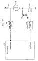
- Fig. 19 is a view for illustrating a control mechanism of a fuel injection apparatus of a conventional type of performing correction based on a power supply voltage.
- the power supply voltage V B applied to a power supply terminal 11 is input to a microcomputer 13 of ECU (Electronic Control Unit) via a power supply voltage input circuit 12.
- ECU Electronic Control Unit
- the microcomputer 13 When the power supply voltage V B is low, the microcomputer 13 outputs a pulse with a waveform for increasing an ON period of a FET 14 to a FET driving circuit 15. In this way, the time the coil current flows into the solenoid 16 is increased, and the fuel injection time is increased. On the other hand, when the power supply voltage V B is high, the fuel injection time is decreased, thus performing control for keeping the fuel injection quantity constant.
- the current flowing into the solenoid 16 immediately after the FET 14 is switched from ON to OFF flows into a Zener diode 18 via a diode 17, the drain voltage of the FET 14 becomes the same as the voltage of the Zener diode 18, power is consumed therein, and the fuel injection is halted.
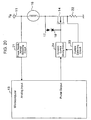
- Fig. 20 is view for illustrating a control mechanism of a fuel injection apparatus of a conventional type of performing constant current control.
- the power supply voltage V B applied to the power supply terminal 11 is detected in a power supply voltage detecting circuit 21, while the coil current is detected in resistance 22 and a current detecting circuit 23 provided for current detection.
- the microcomputer 13 and constant current driving circuit 24 control so that the coil current does not vary with variations in power supply voltage V B .
- an injection module that pressurizes fuel to inject, as distinct from the conventional type of injector that injects fuel pressurized and fed in/from a fuel pump or regulator.
- This injection module has a characteristic that an injection quantity is affected by a coil current for driving a fuel injection solenoid, and therefore, has a problem that it is not possible to perform accurate correction of the injection quantity only by simply increasing/decreasing a driving pulse width in the control mechanism that performs correction based on the power supply voltage as described above.
- a coil current value is detected at the time a predetermined time has elapsed since the start of driving of a fuel injection solenoid, and based on the detection value or on the detection value and a driving pulse width (required driving pulse width) required from a necessary fuel quantity (required fuel injection quantity), an actual driving pulse width is increased or decreased.
- the required driving pulse width corresponds to a driving pulse width in the injection system.
- the actual driving pulse width of the fuel injection solenoid is corrected based on a coil current value after a predetermined time has elapsed since the start of driving of the solenoid, or on the coil current value and the required driving pulse width.
- the final fuel injection driving pulse width Tout of the fuel injection solenoid i.e. the actual driving pulse width is obtained by equation (1) as described above using the declination correction value Td and the waste time offset value Toffset obtained based on the coil current value after a lapse of the predetermined time since the start of driving of the solenoid.
- a current driving pulse width is corrected based on a coil current value detected in the last fuel injection.
- a driving pulse width is not limited to correction based on the detection value after detecting the coil current, and further, is corrected using a correction value close to a current driving state, thereby providing the time required for calculation with lead time.
- a driving pulse width is corrected based on the power supply voltage, instead of the coil current value. According to this invention, even when the coil current value of the last fuel injection is not referred to, it is possible to correct a driving pulse width from the first driving, using a correction value obtained based on the power supply voltage.
- Fig. 1 is a view showing a schematic configuration of an injection module system to which is applied a fuel injection method according to the first embodiment of the present invention.
- the injection module system has its basic configuration a plunger pump 32 as an electromagnetically driven pump that pressurizes and feeds fuel inside a fuel tank 31, an inlet orifice nozzle 33 having an orifice portion through which the fuel with the predetermined pressure pressurized and fed in/from the plunger pump 32, an injection nozzle 34 that injects the fuel passed through the inlet orifice nozzle 33 with the pressure higher than a predetermined value to an intake passage (of an engine), and a driving driver 35, a control unit (ECU) 36 and others as control means for issuing a control signal to the plunger pump 32 or the like based on operation information of the engine and on a value of coil current flowing through a solenoid of the plunger pump 32.
- a plunger pump 32 as an electromagnetically driven pump that pressurizes and feeds fuel inside a fuel tank 31, an inlet orifice
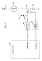
- Fig .2 is a view for illustrating a control mechanism of the injection module system to which is applied the fuel injection method according to the first embodiment of the present invention.
- a solenoid 46 composes the plunger pump 32.
- the driving driver 35 includes switching elements to drive the solenoid 46 such as, for example, an N-channel FET 44, FET driving circuit 45, current detection resistance 52, current detecting circuit 53, diode 47 and Zener diode 48.
- the Zener diode 48 is to make the drain voltage of the FET 44 the same as the voltage of the Zener diode 48 to consume the solenoid current when the FET 44 is switched from ON to OFF.
- a microcomputer 43 is included in the control unit 36.
- One end of the solenoid 46 is connected to a power supply terminal 41 to which the power supply voltage V B is applied.
- the other end of the solenoid 46 is connected to the drain of the FET 44, and the gate of the FET 44 via the diode 47 and Zener diode 48.
- To the gate of the FET 44 is input a driving pulse that is generated in the FET driving circuit 45 based on a control signal output from the microcomputer 43.
- the source of the FET 44 is grounded via the current detection resistance 52.
- a current coil current
- a level of the current flowing into the resistance 52 is input to the current detecting circuit 53 as a voltage signal, a current value is detected in the circuit 53, and the detection value is input to the microcomputer 43.
- Fig. 3 is a waveform chart showing a waveform of each of a driving pulse (hereinafter, referred to as a required driving pulse) 61 required from a required fuel injection quantity, a coil current 62, and an actually output driving pulse (hereinafter, referred to as an output driving pulse) 63.
- a driving pulse hereinafter, referred to as a required driving pulse
- Pw is a pulse width of the required driving pulse 61, i.e.
- Tr is a time elapsed between the start of driving of the solenoid 46 and detection of a value of the coil current 62
- Ir is a detection value of the coil current at the time Tr has elapsed since the start of driving of the solenoid 46
- Pr is a correction value of the pulse width obtained based on the detection value Ir
- Pout is a pulse width of the output driving pulse 63.
- the output driving pulse 63 rises in synchronization with a rising edge of the required driving pulse 61, and thereby the coil current 62 starts flowing. Then, at the time a predetermined time, not limited particularly, for example, 2ms has elapsed, the detection value Ir of the coil current 62 is detected. Based on the detection value Ir and required driving pulse width Pw, the correction value Pr of the driving pulse is obtained. Based on the correction value Pr, the required driving pulse width Pw is corrected, and a driving pulse with the pulse width Pout is actually supplied to the FET 44.
- Fig. 4 is a conceptual view for illustrating a scheme of obtaining the pulse width Pout of the output driving pulse 63.
- a correction pulse width calculation processing section 71 obtains the correction value Pr of a pulse width based on the required driving pulse width Pw and the detection value Ir of the coil current.
- a calculator (that is not limited particularly, but an adder in the figure) 72 adds the correction value Pr to the required driving pulse width Pw, and thus obtains the pulse width Pout of the output driving pulse 63.
- the control unit 36 includes the correction pulse width calculation processing section 71 and calculator 72.
- Fig. 5 is a chart for conceptually illustrating a scheme of obtaining the correction value Pr of the driving pulse.
- a correction value map 8 is prepared where the detection value Ir of the coil current is plotted on the horizontal axis, the required driving pulse width Pw is plotted on the vertical axis, and correction values Pr are mapped corresponding to various combinations of Ir and Pw.
- the correction values Pr corresponding to combinations of Ir and Pw are obtained in advance by experiment or the like.
- the correction value map 8 as shown in Fig. 5, when each of the correction values Pr is represented by a height perpendicular to both the vertical axis and horizontal axis, a so-called three-dimensional map is obtained.
- the driving pulse width Pout to actually switch ON/OFF the FET 44 for driving the solenoid 46 is corrected based on the detection value Ir of the coil current after the predetermined time has elapsed since the start of driving of the solenoid 46 and on the driving pulse width Pw required from the required fuel injection quantity, the relationship between the required fuel injection quantity and actual fuel injection quantity is linear in the injection module that pressurizes the fuel to inject, and the fuel injection quantity can be corrected accurately. Further, according to the first embodiment, the need is eliminated for a power supply voltage detecting circuit, constant current driving circuit or the like which is used conventionally, and therefore, it is possible to simplify the control circuit and reduce the number of components.
- a fuel injection method will be described below, using as an example a case of applying the injection module system as illustrated in Figs. 1 and 2. Redundant descriptions are eliminated on the configuration of the injection module system.
- a fuel injection quantity is affected by the driving current passing through the solenoid 46, i.e. the coil current.
- Fig. 6 shows the relationship between the fuel injection quantity Q and driving pulse width T of the solenoid. As shown in Fig. 6, the fuel injection quantity is zero until a pulse width becomes a certain value (Toffset) from zero, and subsequently, a value of the fuel injection quantity increases with a declination Td as the pulse width increases.
- the time during which the pulse width varies from zero to Toffset is called waste time or ineffective time, and does not affect the fuel injection quantity.
- This Toffset is a waste time offset value in the specification.
- the declination Td is a ratio between an increase in required fuel injection quantity Qc and an increase in driving pulse width, and is defined as a declination correction value in the specification.
- a driving pulse width (referred to as final fuel injection driving pulse width Tout) required to obtain the required fuel injection quantity Qc accurately is expressed by equation (1) as described earlier.
- the waste time offset value Toffset is the function of a value of the coil current flowing through the solenoid at the time the predetermined time Tr (for example, 2ms) has elapsed since the start of driving of the solenoid.
- Tr for example, 2ms
- a value of Toffset is obtained corresponding to a value of the detection value Ir at this point.
- the value of Toffset is obtained, for example, from the two-dimensional map where values of Toffset are mapped in relation to Ir. The map is obtained in advance by experiment or the like.
- the declination correction value Td is the function of the detection value Ir of the coil current after a lapse of the predetermined time since the start of driving of the solenoid, as in Toffset. Accordingly, the value of Td is obtained, for example, from the two-dimensional map where values of Td are mapped in relation to Ir.
- the declination correction value Td is the function of the detection value Ir of the coil current and required fuel injection quantity Qc. Accordingly, in this case, Td is obtained using a three-dimensional map where values of Td are mapped in relation to Ir and Qc. These maps are obtained in advance by experiment or the like.
- Fig. 7 shows an example of the relationship between the detection value Ir of the coil current, actual fuel injection quantity Qout and final fuel injection driving pulse width Tout when Ir varies.
- Fig. 8 shows an example of the relationship between the waste time offset value Toffset and detection value Ir of the coil current.
- the relationship between the declination correction value Td and detection value Ir of the coil current is only the relationship as shown in Fig. 9, independently of the value of the required fuel injection quantity Qc.
- the relationship between Qc and Tout is not linear, the relationship as shown in Fig. 9 is present with respect to each of various required fuel injection quantities Qc.
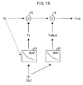
- Fig. 10 is a conceptual view for illustrating a scheme of obtaining the final fuel injection driving pulse width Tout in the second embodiment.
- a multiplier 75 multiplies the required fuel injection quantity Qc by the declination correction value Td.
- the declination correction value Td is obtained from a map 81 based on the detection value Ir of the coil current at the time a predetermined time has elapsed since the start of driving of the solenoid.
- the map 81 is, for example, the characteristic chart as shown in Fig. 9, or equivalent to the chart.
- the declination value Td is the function of the detection value Ir of the coil current and required fuel injection quantity Qc, and Qc is also considered as well as Ir.
- an adder 76 adds the waste time offset value Toffset to a value of Qc x Td.
- the waste time offset value Toffset is obtained from a map 82 based on the detection value Ir of the coil current at the time a predetermined time has elapsed since the start of driving of the solenoid.
- the map 82 is, for example, the characteristic chart as shown in Fig. 8, or equivalent to the chart.
- the final fuel injection driving pulse width Tout is obtained.
- the control unit 36 includes the multiplier 75 and adder 76. Maps 81 and 82 are stored in a non-volatile memory in the control unit 36.
- the declination correction value Td is obtained based on the detection value Ir of the coil current after a lapse of the predetermined time Tr since the start of driving of the solenoid 46, or on the Ir and required fuel injection quantity Qc, the waste time offset value Toffset is obtained based on the Ir, and the final fuel injection driving pulse width Tout is corrected using the Toffset and Td. Therefore, in the injection module that pressurizes fuel to inject, even when the relationship is not linear between the driving pulse width and fuel injection quantity, it is possible to correct the fuel injection quantity accurately.
- the declination correction value Td and waste time offset value Toffset are obtained from respective two-dimensional maps, there are advantages that calculation to obtain correction values is simplified and that a memory usage amount by the maps is reduced, as compared to the case of using three-dimensional maps for correction. Furthermore, according the second embodiment, the need is eliminated for a power supply voltage detecting circuit, constant current driving circuit or the like which is used conventionally, and therefore, it is possible to simplify the control circuit and reduce the number of components.
- Fig. 11 is a view for illustrating a control mechanism in an injection module system to which is applied a fuel injection method according to the third embodiment of the present invention.
- the injection module system in the third embodiment has a configuration with the injection module system as illustrated in Fig. 2 and further a power supply voltage detecting circuit 49 that detects the power supply voltage V B and supplies the detection value to the microcomputer 43.
- the other structure is the same as the configuration as illustrated in Fig. 2, and the same structural elements as in Fig. 2 are assigned the same reference numerals to omit descriptions thereof.
- the fuel injection method according to the third embodiment is the same as the fuel injection method in the second embodiment except following respects. That is, in the second embodiment, in the same fuel injection cycle, the coil current is detected after a lapse of a predetermined time since the start of driving of the solenoid 46, the final fuel injection driving pulse width Tout is obtained based on the declination correction value Td and waste time offset value Toffset obtained based on the detection value Ir, and the fuel injection is halted at the timing of Tout. In other words, the correction based on the detection value Ir of the coil current is reflected in the driving pulse width of the time the coil current is detected.
- the declination correction value Td and waste time offset value Toffset are obtained based on a detection value Ir of the coil current detected after a lapse of a predetermined time since the start of driving of the solenoid 46 in a last fuel injection cycle, a current-cycle final fuel injection driving pulse width Tout is obtained using the declination correction value Td and Toffset, and the current fuel injection is halted at the timing of the Tout.
- a driving pulse width is corrected in current fuel injection.
- the detection value Ir of the coil current detected in the last fuel injection cycle is, for example, stored in Random Access Memory (RAM) (not shown) in the microcomputer 43.
- the last fuel injection cycle is not present, and therefore, data of Ir of the last fuel injection to be referred to is not present to obtain the declination correction value Td and waste time offset value Toffset.
- the power supply voltage V B decreases extremely, the microcomputer 43 is thereby reset, and it is not possible to refer to data of Ir of the last fuel injection.
- the power supply voltage detecting circuit 49 detects the power supply voltage V B , and based on the detection value, the declination correction value Td and waste time offset time Toffset are obtained.
- Fig. 12 shows an example of the relationship between a detection value of the power supply voltage V B , actual fuel injection quantity Qout, and final fuel injection driving pulse width Tout when the voltage V B varies.
- a map on which the waste time offset time Toffset is mapped in relation to the power supply voltage V B and another map on which the declination correction value Td is mapped in relation to the power supply voltage V B are obtained in advance by experiment or the like and stored in a non-volatile memory in the control unit 36, which is not shown in the figure particularly.
- the final fuel injection driving pulse width Pout is obtained by equation (1) described earlier using the declination correction value Td and waste time offset value Toffset obtained based on the detection value of the power supply voltage V B .
- the final fuel injection driving pulse width Tout is corrected based on the detection value of the power supply voltage V B at the time of starting the engine and at the first driving time to drive the solenoid 46 again after a halt of fuel injection, for example, due to a fuel cut, while being corrected based on the detection value Ir of the coil current detected in the last fuel injection in other cases, as in the second embodiment, it is possible to correct the fuel injection quantity accurately in the injection module that pressurizes fuel to inject.
- the maps for use in correction calculation are two-dimensional maps, there are advantages that the correction calculation is simplified and that a memory usage amount by the maps is reduced. Furthermore, according to the third embodiment, the need is eliminated for a power supply voltage detecting circuit or the like which is used conventionally, and therefore, it is possible to simplify the control circuit and reduce the number of components.
- a fuel injection method is a method for preventing the correction value Ir of the coil current from differing from an original value due to a shift of the detection timing in detecting the coil current after a lapse of a predetermined time since the start of driving of the solenoid 46 in the first to third embodiments as described above.
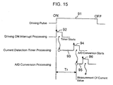
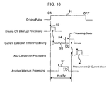
- the injection module system with the configuration as illustrated in Fig. 2 or 11 performs software processing, as shown in Fig. 15, where a timer to count the detection time Tr of the coil current starts at an interrupt 92 for switching ON a driving pulse 91, thereby the state becomes interrupt wait 93, a current detection A/D converter starts at a count up interrupt 94 of the timer, thereby the state becomes interrupt wait 95, and an A/D conversion value is read at an A/D conversion finish interrupt 96.
- the timer and current detection A/D converter are integrally provided in the microcomputer 43.
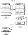
- Fig. 13 is a flowchart illustrating an example of processing procedures in the fuel injection method according to the fourth embodiment of the present invention.
- current detection timer processing is started.
- the present time i.e. time T 2 A/D conversion is scheduled to execute is measured (step S134), and an elapsed time T 2 -T 1 between time T 1 and time T s is obtained (step S135).
- the elapsed time T 2 -T is compared with a beforehand set time (step S136). As a result of comparison, when the elapsed time T 2 -T 1 is within the set time, the current detection A/D converter is started to start A/D conversion (step S137), and the current detection timer processing is finished.
- step S138 when the A/D conversion finish interrupt occurs, an A/D conversion value is read in the A/D conversion processing, and the detection value of the coil current is updated using the read value (step S138), and all the processing is finished.
- the solenoid driving pulse width is corrected as described in the first to third embodiments.
- step S136 when the elapsed time (T 2 -T 1 ) exceeds the set time, the current detection A/D converter is not started, and all the processing is finished.
- the solenoid driving pulse width is corrected.
- Fig. 14 shows A/F variations that are suppressed by the fourth embodiment
- Fig. 18 shows A/F variations in the case where the fourth embodiment is not applied.
- ⁇ A/F is 1.5 in Fig. 14, while ⁇ A/F is 2.5 in Fig. 18.
- the present invention is not limited to the aforementioned embodiments, and is capable of being carried out with various modifications thereof.
- the calculator 72 which applies the correction value Pr of the pulse width to the required driving pulse width Pw, is not limited to an adder, and may be a subtracter, multiplier, divider, a combination thereof, or device for performing other calculation.
- the correction value Pr instead of obtaining the correction value Pr using the correction map 8, it may be possible to derive a relational equation between the detection value Ir of the coil current, required driving pulse width Pw and correction value Pr and obtain the correction value Pr from the relational equation.
- the present invention is not limited to the injection module, and applicable to the conventional type of injector.
- the correction value Pr of the pulse width is obtained only based on the detection value Ir of the coil current. The reason is that the relationship between the driving pulse width and fuel injection quantity is linear in the conventional type of injector, because of having a configuration where a valve member operates according to a driving start instruction, and fuel beforehand pressurized by a fuel pump is injected with the pressure.
- an actual driving pulse width for driving a fuel injection solenoid is corrected based on a coil current value after a lapse of a predetermined time since the start of driving of the solenoid, a fuel injection quantity is corrected accurately, and the need is eliminated for a constant current driving circuit or the like used conventionally, resulting in an advantage of obtaining a fuel injection method capable of simplifying the control circuit and of reducing the number of components.
- the relationship is linear between the driving pulse width and fuel injection quantity in the injection module that pressurizes the fuel to inject, and there is an advantage of obtaining a fuel injection method enabling the fuel injection quantity to be corrected accurately.
Landscapes
- Engineering & Computer Science (AREA)
- Chemical & Material Sciences (AREA)
- Combustion & Propulsion (AREA)
- Mechanical Engineering (AREA)
- General Engineering & Computer Science (AREA)
- Electrical Control Of Air Or Fuel Supplied To Internal-Combustion Engine (AREA)
- Fuel-Injection Apparatus (AREA)
- Magnetically Actuated Valves (AREA)
Abstract
Description
Claims (7)
- A fuel injection method comprising the steps of:starting driving of a fuel injection solenoid;detecting a coil current value after a lapse of a predetermined time since the time of starting the driving of the solenoid;obtaining a correction value to correct timing for halting the driving of the solenoid, based on the coil current value detected; andhalting the driving of the solenoid by adjusting the timing for halting the driving using the correction value obtained.
- The fuel injection method according to claim 1, wherein the correction value is determined based on a detection value of the coil current and a required driving pulse width of the solenoid.
- The fuel injection method according to claim 2, wherein correction values are obtained in advance corresponding to various combinations of the detection value of the coil current and the required driving pulse width of the solenoid, and the correction value is selected corresponding to a combination of the detection value of the coil current and the required driving pulse width of the solenoid.
- The fuel injection method according to claim 1, wherein the step of obtaining a correction value to correct timing for halting the driving of the solenoid includes the steps of:obtaining a declination correction value indicated by a ratio between an increase in required fuel injection quantity and an increase in driving pulse width of the solenoid determined corresponding to either or both of the coil current value and a required fuel injection quantity based on the coil current detected, and further obtaining a waste time offset value elapsing until fuel injection is started after starting the driving of the solenoid determined corresponding to the coil current value; andmultiplying the declination correction value by the required fuel injection quantity, adding the waste time offset value to a multiplication result, and using a resultant value as a final fuel injection driving pulse width of the solenoid, halting the driving of the solenoid.
- The fuel injection method according to any one of claims 1 to 4, wherein a correction value, which is obtained based on a coil current value after a lapse of a predetermined time since the time of starting driving of the solenoid in last fuel injection, is used in the step of halting current driving of the solenoid.
- The fuel injection method according to any one of claims 1 to 4, further comprising the step of:measuring a power supply voltage, and obtaining a correction value, based on a measurement value of the power supply voltage, to correct the timing for halting the driving of the solenoid at the time of starting an engine or only at the first driving time to resume once halted fuel injection.
- The fuel injection method according to any one of claims 1 to 4, wherein an actual elapsed time is measured between the time of starting the driving of the solenoid and timing to detect a coil current value, and when a measurement value is within a predetermined value, the coil current value is detected and used as a reference to obtain the correction value, while when the measurement value exceeds the predetermined value, a coil current value last detected is used as the reference to obtain the correction value.
Applications Claiming Priority (5)
| Application Number | Priority Date | Filing Date | Title |
|---|---|---|---|
| JP2001235622 | 2001-08-02 | ||
| JP2001235622 | 2001-08-02 | ||
| JP2001367695 | 2001-11-30 | ||
| JP2001367695A JP4119116B2 (en) | 2001-08-02 | 2001-11-30 | Fuel injection method |
| PCT/JP2002/007744 WO2003014555A1 (en) | 2001-08-02 | 2002-07-30 | Fuel injection method |
Publications (2)
| Publication Number | Publication Date |
|---|---|
| EP1424476A1 true EP1424476A1 (en) | 2004-06-02 |
| EP1424476A4 EP1424476A4 (en) | 2008-12-31 |
Family
ID=26619870
Family Applications (1)
| Application Number | Title | Priority Date | Filing Date |
|---|---|---|---|
| EP02751804A Withdrawn EP1424476A4 (en) | 2001-08-02 | 2002-07-30 | FUEL INJECTION PROCESS |
Country Status (5)
| Country | Link |
|---|---|
| EP (1) | EP1424476A4 (en) |
| JP (1) | JP4119116B2 (en) |
| KR (1) | KR20040018535A (en) |
| CN (1) | CN100366881C (en) |
| WO (1) | WO2003014555A1 (en) |
Cited By (12)
| Publication number | Priority date | Publication date | Assignee | Title |
|---|---|---|---|---|
| WO2005019633A3 (en) * | 2003-08-18 | 2005-11-03 | New Power Concepts Llc | Metering fuel pump |
| WO2006062583A1 (en) * | 2004-12-09 | 2006-06-15 | Caterpillar Inc. | Method for detecting and controlling movement of an actuated component |
| EP1596055A4 (en) * | 2003-02-03 | 2008-12-31 | Mikuni Kogyo Kk | FUEL INJECTION METHOD AND DEVICE |
| DE102010001261A1 (en) | 2010-01-27 | 2011-07-28 | Robert Bosch GmbH, 70469 | Control device for an electromagnetic actuator and method for operating an electromagnetic actuator |
| GB2497977A (en) * | 2011-12-23 | 2013-07-03 | Perkins Engines Co Ltd | Fault detection and correction in valve assemblies |
| WO2014181166A3 (en) * | 2013-05-10 | 2015-02-19 | Toyota Jidosha Kabushiki Kaisha | Control apparatus for fuel injection valve and method thereof |
| DE112014002856B4 (en) | 2013-07-10 | 2019-08-01 | Hitachi Automotive Systems, Ltd. | Control device for internal combustion engine |
| US11285399B2 (en) | 2008-08-15 | 2022-03-29 | Deka Products Limited Partnership | Water vending apparatus |
| US11826681B2 (en) | 2006-06-30 | 2023-11-28 | Deka Products Limited Partneship | Water vapor distillation apparatus, method and system |
| US11885760B2 (en) | 2012-07-27 | 2024-01-30 | Deka Products Limited Partnership | Water vapor distillation apparatus, method and system |
| US11884555B2 (en) | 2007-06-07 | 2024-01-30 | Deka Products Limited Partnership | Water vapor distillation apparatus, method and system |
| DE112018000220B4 (en) | 2017-02-21 | 2024-09-19 | Hitachi Astemo, Ltd. | Electronic control device and abnormality/normality determination method of electronic control device |
Families Citing this family (17)
| Publication number | Priority date | Publication date | Assignee | Title |
|---|---|---|---|---|
| TWI259235B (en) * | 2002-03-26 | 2006-08-01 | Mikuni Kogyo Kk | Fuel injection controller and controlling method |
| US8069676B2 (en) | 2002-11-13 | 2011-12-06 | Deka Products Limited Partnership | Water vapor distillation apparatus, method and system |
| US8511105B2 (en) | 2002-11-13 | 2013-08-20 | Deka Products Limited Partnership | Water vending apparatus |
| JPWO2005088110A1 (en) * | 2004-03-11 | 2008-01-31 | 株式会社ミクニ | Fuel injection control method and fuel injection control device |
| CN100356052C (en) * | 2005-01-07 | 2007-12-19 | 清华大学 | Integrated bivoltage electromagnet valve driven circuit |
| JP4468912B2 (en) * | 2006-03-15 | 2010-05-26 | 三菱電機株式会社 | Fuel injection device |
| DE102006059625A1 (en) | 2006-12-14 | 2008-06-19 | Robert Bosch Gmbh | Device and method for controlling an electromagnetic valve |
| KR101826492B1 (en) | 2007-06-07 | 2018-03-22 | 데카 프로덕츠 리미티드 파트너쉽 | Water vapor distillation apparatus, method and system |
| JP2010174865A (en) * | 2009-02-02 | 2010-08-12 | Denso Corp | Method for controlling liquid injecting/feeding device |
| JP5058239B2 (en) * | 2009-10-30 | 2012-10-24 | 日立オートモティブシステムズ株式会社 | Fuel injection control device for internal combustion engine |
| JP5862442B2 (en) * | 2012-05-09 | 2016-02-16 | 株式会社デンソー | Solenoid valve drive control device |
| JP5849994B2 (en) * | 2013-06-12 | 2016-02-03 | 株式会社デンソー | Actuator drive |
| CN103835850B (en) * | 2014-02-08 | 2016-03-16 | 潍柴动力股份有限公司 | A kind of monoblock pump fuel feeding control method for correcting and device |
| KR101567201B1 (en) | 2014-03-31 | 2015-11-09 | 현대자동차주식회사 | Device for correction an injector characteristic |
| DE102016206997B4 (en) * | 2016-04-25 | 2023-08-10 | Vitesco Technologies GmbH | Method for operating a piezo actuator as a sensor and motor vehicle |
| JP6544293B2 (en) * | 2016-05-06 | 2019-07-17 | 株式会社デンソー | Fuel injection control device |
| JP6356754B2 (en) * | 2016-09-13 | 2018-07-11 | 本田技研工業株式会社 | Control device for internal combustion engine |
Family Cites Families (9)
| Publication number | Priority date | Publication date | Assignee | Title |
|---|---|---|---|---|
| CN85104734B (en) * | 1985-06-20 | 1987-12-16 | 株式会社日立制作所 | Internal Combustion Engine Fuel Injection Controller |
| US4974622A (en) * | 1990-01-23 | 1990-12-04 | Borg-Warner Automotive, Inc. | Self compensation for duty cycle control |
| DE4308811B9 (en) | 1992-07-21 | 2004-08-19 | Robert Bosch Gmbh | Method and device for controlling a solenoid-controlled fuel metering device |
| JPH07224708A (en) * | 1994-02-10 | 1995-08-22 | Nippondenso Co Ltd | Fuel injection control device for internal combustion engine |
| DE19513878A1 (en) * | 1995-04-12 | 1996-10-17 | Bosch Gmbh Robert | Method and device for controlling an electromagnetic consumer |
| JPH1089139A (en) * | 1996-09-20 | 1998-04-07 | Hitachi Ltd | Engine rotation fluctuation detection device and control device |
| JP3529577B2 (en) * | 1997-02-14 | 2004-05-24 | 本田技研工業株式会社 | Fuel injector control device |
| JP2000337224A (en) * | 1999-05-27 | 2000-12-05 | Hitachi Ltd | Engine control device |
| JP3932474B2 (en) * | 1999-07-28 | 2007-06-20 | 株式会社日立製作所 | Electromagnetic fuel injection device and internal combustion engine |
-
2001
- 2001-11-30 JP JP2001367695A patent/JP4119116B2/en not_active Expired - Fee Related
-
2002
- 2002-07-30 WO PCT/JP2002/007744 patent/WO2003014555A1/en not_active Ceased
- 2002-07-30 CN CNB028150783A patent/CN100366881C/en not_active Expired - Fee Related
- 2002-07-30 EP EP02751804A patent/EP1424476A4/en not_active Withdrawn
- 2002-07-30 KR KR10-2004-7001389A patent/KR20040018535A/en not_active Ceased
Cited By (17)
| Publication number | Priority date | Publication date | Assignee | Title |
|---|---|---|---|---|
| EP1596055A4 (en) * | 2003-02-03 | 2008-12-31 | Mikuni Kogyo Kk | FUEL INJECTION METHOD AND DEVICE |
| WO2005019633A3 (en) * | 2003-08-18 | 2005-11-03 | New Power Concepts Llc | Metering fuel pump |
| WO2006062583A1 (en) * | 2004-12-09 | 2006-06-15 | Caterpillar Inc. | Method for detecting and controlling movement of an actuated component |
| US7469679B2 (en) | 2004-12-09 | 2008-12-30 | Caterpillar Inc. | Method for detecting and controlling movement of an actuated component |
| US11826681B2 (en) | 2006-06-30 | 2023-11-28 | Deka Products Limited Partneship | Water vapor distillation apparatus, method and system |
| US11884555B2 (en) | 2007-06-07 | 2024-01-30 | Deka Products Limited Partnership | Water vapor distillation apparatus, method and system |
| US11285399B2 (en) | 2008-08-15 | 2022-03-29 | Deka Products Limited Partnership | Water vending apparatus |
| DE102010001261A1 (en) | 2010-01-27 | 2011-07-28 | Robert Bosch GmbH, 70469 | Control device for an electromagnetic actuator and method for operating an electromagnetic actuator |
| US9528456B2 (en) | 2011-12-23 | 2016-12-27 | Perkins Engines Company Limited | Fault detection and correction in valve assemblies |
| GB2497977B (en) * | 2011-12-23 | 2014-02-12 | Perkins Engines Co Ltd | Fault detection and correction in valve assemblies |
| GB2497977A (en) * | 2011-12-23 | 2013-07-03 | Perkins Engines Co Ltd | Fault detection and correction in valve assemblies |
| US11885760B2 (en) | 2012-07-27 | 2024-01-30 | Deka Products Limited Partnership | Water vapor distillation apparatus, method and system |
| US12590917B2 (en) | 2012-07-27 | 2026-03-31 | Deka Products Limited Partneship | Water vapor distillation apparatus, method and system |
| WO2014181166A3 (en) * | 2013-05-10 | 2015-02-19 | Toyota Jidosha Kabushiki Kaisha | Control apparatus for fuel injection valve and method thereof |
| DE112014002856B4 (en) | 2013-07-10 | 2019-08-01 | Hitachi Automotive Systems, Ltd. | Control device for internal combustion engine |
| US10502155B2 (en) | 2013-07-10 | 2019-12-10 | Hitachi Automotive Systems, Ltd. | Control device for internal combustion engine |
| DE112018000220B4 (en) | 2017-02-21 | 2024-09-19 | Hitachi Astemo, Ltd. | Electronic control device and abnormality/normality determination method of electronic control device |
Also Published As
| Publication number | Publication date |
|---|---|
| WO2003014555A1 (en) | 2003-02-20 |
| JP4119116B2 (en) | 2008-07-16 |
| EP1424476A4 (en) | 2008-12-31 |
| CN100366881C (en) | 2008-02-06 |
| JP2003113732A (en) | 2003-04-18 |
| CN1537197A (en) | 2004-10-13 |
| KR20040018535A (en) | 2004-03-03 |
Similar Documents
| Publication | Publication Date | Title |
|---|---|---|
| EP1424476A1 (en) | Fuel injection method | |
| EP1582725B1 (en) | Fuel-injection control method and apparatus | |
| CN102345519B (en) | Fuel injection control apparatus for internal combustion engine | |
| JP5053868B2 (en) | Fuel injection control device | |
| EP1953372A2 (en) | Solenoid valve driver and fuel injection system equipped with the same for compensating lag of operation of solenoid valve | |
| EP1905993A2 (en) | Apparatus and system for driving fuel injectors with piezoelectric elements | |
| KR101601432B1 (en) | Device for control an injector driving | |
| US11371458B2 (en) | Injection control device | |
| EP1489290B1 (en) | Fuel injection controller and controlling method | |
| WO2014207523A2 (en) | Drive system and drive method for fuel injection valve | |
| EP1596055A1 (en) | Method and device for fuel injection | |
| JP4067384B2 (en) | Fuel injection method | |
| CN101018945A (en) | Method and device for detecting the idle stroke of injectors | |
| JP3265812B2 (en) | Fuel injection control device for internal combustion engine | |
| CA1288842C (en) | Low voltage supply control system for fuel injectors | |
| US20060086333A1 (en) | Engine control method and system having a voltage increasing circuit | |
| JP4111848B2 (en) | Fuel injection control method and control device | |
| JP3957529B2 (en) | Fuel injection method | |
| JPWO2005088110A1 (en) | Fuel injection control method and fuel injection control device | |
| JP3869288B2 (en) | Fuel injection method | |
| JP2007016648A (en) | Fuel injection device | |
| JP3747485B2 (en) | Fuel injection device for internal combustion engine | |
| JP2004270594A (en) | Fuel injection control method and control device | |
| US20030196642A1 (en) | Method and device for controlling fuel metering into an internal combustion engine | |
| JPH11210531A (en) | Injector drive |
Legal Events
| Date | Code | Title | Description |
|---|---|---|---|
| PUAI | Public reference made under article 153(3) epc to a published international application that has entered the european phase |
Free format text: ORIGINAL CODE: 0009012 |
|
| 17P | Request for examination filed |
Effective date: 20040225 |
|
| AK | Designated contracting states |
Kind code of ref document: A1 Designated state(s): DE FR GB IT |
|
| A4 | Supplementary search report drawn up and despatched |
Effective date: 20081127 |
|
| RIC1 | Information provided on ipc code assigned before grant |
Ipc: F02D 41/24 20060101ALN20081121BHEP Ipc: F02D 41/06 20060101ALI20081121BHEP Ipc: F02M 51/00 20060101ALI20081121BHEP Ipc: F02D 41/20 20060101AFI20030227BHEP Ipc: F02D 41/34 20060101ALI20081121BHEP |
|
| 17Q | First examination report despatched |
Effective date: 20090303 |
|
| STAA | Information on the status of an ep patent application or granted ep patent |
Free format text: STATUS: THE APPLICATION IS DEEMED TO BE WITHDRAWN |
|
| 18D | Application deemed to be withdrawn |
Effective date: 20100803 |