EP1424417A1 - Composite needle of knitting machine - Google Patents
Composite needle of knitting machine Download PDFInfo
- Publication number
- EP1424417A1 EP1424417A1 EP02758870A EP02758870A EP1424417A1 EP 1424417 A1 EP1424417 A1 EP 1424417A1 EP 02758870 A EP02758870 A EP 02758870A EP 02758870 A EP02758870 A EP 02758870A EP 1424417 A1 EP1424417 A1 EP 1424417A1
- Authority
- EP
- European Patent Office
- Prior art keywords
- needle
- dust
- slider
- hook
- needle body
- Prior art date
- Legal status (The legal status is an assumption and is not a legal conclusion. Google has not performed a legal analysis and makes no representation as to the accuracy of the status listed.)
- Granted
Links
- 239000002131 composite material Substances 0.000 title claims abstract description 33
- 238000009940 knitting Methods 0.000 title claims abstract description 28
- 239000000428 dust Substances 0.000 claims description 37
- 210000002105 tongue Anatomy 0.000 description 13
- 238000009825 accumulation Methods 0.000 description 5
- 238000005299 abrasion Methods 0.000 description 3
- 230000001976 improved effect Effects 0.000 description 3
- 238000006073 displacement reaction Methods 0.000 description 2
- 239000000463 material Substances 0.000 description 2
- 239000002245 particle Substances 0.000 description 2
- 230000000149 penetrating effect Effects 0.000 description 2
- 238000007599 discharging Methods 0.000 description 1
- 230000007257 malfunction Effects 0.000 description 1
- 238000000034 method Methods 0.000 description 1
- 230000002265 prevention Effects 0.000 description 1
- 238000003466 welding Methods 0.000 description 1
Images




Classifications
-
- D—TEXTILES; PAPER
- D04—BRAIDING; LACE-MAKING; KNITTING; TRIMMINGS; NON-WOVEN FABRICS
- D04B—KNITTING
- D04B35/00—Details of, or auxiliary devices incorporated in, knitting machines, not otherwise provided for
- D04B35/02—Knitting tools or instruments not provided for in group D04B15/00 or D04B27/00
- D04B35/06—Sliding-tongue needles
-
- D—TEXTILES; PAPER
- D04—BRAIDING; LACE-MAKING; KNITTING; TRIMMINGS; NON-WOVEN FABRICS
- D04B—KNITTING
- D04B35/00—Details of, or auxiliary devices incorporated in, knitting machines, not otherwise provided for
- D04B35/32—Devices for removing lint or fluff
Definitions
- the present invention relates to a knitting needle used in a knitting machine.
- the present invention relates to a composite needle that has a needle body having at the tip end a hook and that has at the tip end tongues structured to have a relative displacement to the needle body section, the tongues work in cooperation with the hook to close and open the hook so that dust adhered to and accumulated in the composite needle can be removed.
- Japanese Patent Publication No. 2946323 proposed by the present applicant discloses a known needle body having at the tip end a hook and a slider in which the needle body and slider have relative displacement to allow the hook to be closed and opened.
- This composite needle has a slider formed with superimposing two blades.
- the blade has a thickness that is thinner than a groove width of a blade storage groove provided in the needle body. This provides a gap between the blades and the groove so that the blades are supported so as to freely advance and recede in the groove.
- the two blades at the slider tip end make contact with the side face part of the hook tip end of the needle body to advance so that the blades are branched left and right.
- the two blades advancing beyond the hook have therebetween a space into which a knitting needle of the opposing needle bed is allowed to enter, thereby carrying out a transferring stitch.
- Such an increased sliding resistance of the slider or deformation of the blade causes the needle to malfunction, thus preventing an accurate knitting operation.
- Such an increased sliding resistance of the slider or deformation of the blade also causes a fear in which a control butt of a needle and a cam for driving the needle cause abrasion and breakage or burn out.
- the present invention has been proposed in view of the above-described problems. It is an object of the present invention to provide a composite needle that can prevent dust or the like from being adhered and accumulated between the blades to prevent the problems as described above from occurring.
- the composite needle according to the present invention is characterized by comprising: a needle body having at the tip end a hook; a slider formed by superposing two blades, wherein the composite needle of the knitting machine is formed such that a blade groove provided in the needle body supports the blades of the slider where the needle body and the slider can separately slide in forward and backward directions, and a dust-collecting plate that is separately formed from the needle body and that extrudes, when viewed from the side, from the blade groove of the needle body in the upward direction and to the hook side of the needle wherein the dust-collecting plate is provided at the tip end of the slider proximate to the needle hook.
- the composite needle is characterized in that it has a hole penetrating the side wall of the blade groove and the bottom face of the blade groove and the hole is fixed when the hole is attached with the projection provided at the lower part of the dust-collecting plate.
- the composite needle is also characterized in that the dust-collecting plate is provided at a position at which a part is at least superposed between an area at which the needle hook removes dust when the slider advances with reference to the needle body and an area at which the needle hook removes dust when the slider recedes from the needle body.
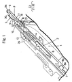
- Fig. 1 illustrates a head part of a composite needle 3 attached to a needle groove 2 provided in a needle bed of the flat knitting machine.
- Fig. 2 is a cutaway partial side view of a needle body 4.
- Fig. 3 is a cross-sectional view taken at the line A-A shown in Fig. 2.
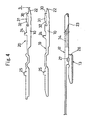
- Fig. 4 is a side view illustrating the details of parts composing a slider 5.
- the composite needle 3 is composed of the needle body 4 and the slider 5.
- the needle body 4 consists of a hook member 6 and a jack 7 having a separate body.
- the hook member 6 and the jack 7 may be provided in an integrated manner but the hook member 6 and the jack 7 in the present embodiment are integrated by engagement of an engagement section 8a and an engagement concave section 8b.
- the hook member 6 includes, from the tip end side, a hook section 9; a body center section 14 for supporting a blade groove 11 for storing a blade section 10 of a slider 5 (described later) and a lower arm section 13 of a slider body section 12; and the above-described engagement concave section 8b the rear end part of which is connected with the engagement section 8a at the tip end of the jack 7.
- the hook member 6 and the jack 7 have an identical thickness that is slightly thinner than the width of the needle groove 2.
- the jack 7 has a curved elastic leg section which extends from the above-described engagement concave section 8b in the rearward direction and in which the rear end makes contact with the bottom of the needle groove 2.
- the jack 7 has at the body center a control butt 15 that is provided in a protruded manner. This control butt 15 is operated to advance and recede while being engaged with the cam provided in a cam carriage (not shown), thereby operating the needle body 4 to slide back and forth.
- the hook member 6 has the blade groove 11 the tip end of which has a dust-collecting plate 16 along the chain line X-X that passes through the tip end of the hook section 9 running in the direction of the length of the needle 3 and from the bottom face of the blade groove 11 in an upper direction vertically, as shown in Fig. 5.
- the dust-collecting plate 16 has a plate-like shape that has a thickness thinner than that of the hook section 9. This dust-collecting plate 16 is provided at a position as described later by a fixing means such as caulking 17 at which the blade groove 11 is divided into "11a" and "11b" left and right.
- This dust-collecting plate 16 has at the front end an inclined plane that is lowered toward the tip end side. This inclined plane functions as the dust removal face 18.
- the dust-collecting plate 16 has substantially the same height as that of the side wall parts 11c and 11d of the blade groove 11 to which the dust-collecting plate 16 is attached.
- This height is substantially equal to or higher than that of the blades 19 and 20 that slide while making contact with the dust-collecting plate 16 (see Fig.2 and Fig. 3).
- the dust-collecting plate 16 is attached at a position at which a part is superposed between an area at which the needle hook removes dust when the slider 5 has maximum advancement with reference to the needle body 4 (Fig. 6-III) and an area of the dust removal face 18 at which the slider 5 has maximum receding with reference to the needle body 4 as shown in Fig. 6-I.
- the dust-collecting plate 16 is attached to the blade groove 11 such that the dust-collecting plate 16 has at the lower part a fitting projection 16a; the hole 11f is provided that communicates the side wall parts 11c and 11d of the blade groove 11 with the bottom face 11e of the blade groove 11; this hole 11f is fitted with the fitting projection 16a to provide the dust-collecting plate 16 having at the lower part the projection 16a that is fixed by the caulking 17 (see Fig. 2 and Fig. 3).
- the dust-collecting plate 16 thus attached to the blade groove 11 removes dust.
- the hook section 9 moves forward from a position at which the slider 5 recedes from the needle body 4 as shown in Fig. 6-I to a position at which the slider 5 makes maximum advancement with reference to the needle body 4 as shown in Fig. 6-III, then the dust in the range ⁇ of the blades 19 and 20 shown by the downward-sloping diagonal lines in Fig. 7 is removed.
- the slider 5 advances from a position at which the slider 5 is at the needle body 4 as shown in Fig. 6-III to a position at which the slider 5 makes maximum advancement with reference to the needle body 4 as shown in Fig.
- the reference numeral 40 denotes a rear part dust removal face provided at the rear end part of the dust-collecting plate 16. This rear dust removal face 40 removes the dust in the rear part of the blades 19 and 20.
- the blade groove 11 has side wall parts 11c and 11d the front ends of which have inclined guide face 21 for guiding the blades 19 and 20 of the slider 5 (which will be described later) in the downward direction (see Fig. 2).
- the slider 5 consists of blades 19 and 20 and the slider body section 12 having a separate member.
- the blades 19 and 20 are provided by superimposing the two plates having substantially the same shape and are attached to the blade grooves 11a and 11b that are divided left and right by the above-described dust-collecting plate 16 so that the blades 19 and 20 are stored to sandwich the dust-collecting plate 16.
- the blades 19 and 20 have at the tip end side the tongues 22 and 22 making contact with the hook tip end part 9a.
- the tongues 22 and 22 have in the rearward direction an engagement section 24 of an angular projection that penetrates the tip end part of the slider body section 12 and that is attached to the circular opening 23 when viewed from the side.
- the blade groove 11 has in the rearward direction connection sections 25 and 25 for providing connection with the slider body section 12.
- the slider body section 12 also has half-cut section 34.
- the dust removal face 18 of the dust-collecting plate 16 discharges the dust collected in the tail part of the needle body 4 out of the needle groove 2 via a space that is provided in the needle plate 1 in the vicinity of the half-cut section 34 and the knitting needle.
- the tongues 22 and 22 of the blades 19 and 20 have a rear anchor section in which a vertical yarn receiving section 30 is provided.
- This yarn receiving section 30 has in the rearward direction a curved section 31 opened to the exterior.
- This inclined plane 32 and inclined guide face 21 provide the lowering means 33 for lowering the slider tip end part into the blade groove 11 of the needle body 4.
- the slider body section 12 has an identical thickness as that of the needle body 4 and has in the rearward direction a control butt (not shown) provided in a protruded manner for controlling forward and backward movements.
- the slider body section 12 has in the lower direction a lower arm section 20a that is branched from the body section.
- This lower arm section 13 has at one side face a longitudinal groove 26 that is cut to have a thin thickness and that is attached to the latter parts of the blades 19 and 20.
- This longitudinal groove 26 has a penetrating hole 27.
- the hole 27 is connected with projections 28 and 28 provided in a protruded manner in the blades 19 and 20 stored in the longitudinal groove 26 by a method such as caulking or welding. This allows the blades 19 and 20 to be fixed with the slider body section 12.
- the dust-collecting plate 16 has a shape having a height higher than that of the blade groove 11 that has a reduced height so as to correspond to the curved section 31 provided in the blade.
- the dust-collecting plate 16 also has a shape that allows wiping away even dust collected in the curved section 31 that is more distant from the lowering means 33 provided in the needle body 4 and that is closer to the hook section 9 of the needle body 4.
- the dust-collecting plate has a shape that protrudes from the needle body 4 in the upward direction and to the hook side.
- the tongues 22 thus widely opened receive the opposing knitting needle to allow the hook (not shown) to enter the tongues 22. Then, the hook receives a knitting yarn of a loop received by the yarn receiving section 30 that is to be subjected to transferring stitch.
- the dust-collecting plate is separately formed from the needle body. This allows the dust-removing plate to easily have a shape that is difficult to be structured such as a reduced gauge knitting needle, by cutting the needle body.
- the dust-collecting plate When the dust-collecting plate is provided with a material different from that of the needle body, the dust-collecting plate can be processed in an easy manner. When the dust-collecting plate is separately formed from the needle body, then the dust-collecting plate can be freely designed regardless of shape, material, hardness, and processing of the needle body as well as the needle bed in the rearward direction, thus providing a dust-collecting plate having a superior function.
- the above-described embodiment is structured with the hook side and tail side of the needle of the dust-collecting plate having an inclined shape, respectively.
- the hook side and the tail side of the needle do not necessarily require an inclined shape.
- such an inclined shape is preferable because dust is lifted from the deeper part of the slider groove to provide an improved effect of discharging dust.
- the composite needle of the knitting machine of the present embodiment allows the shape of the dust-collecting plate not to be limited by the shape of needle body, thereby providing a dust-collecting plate having an improved effect of removing dust.
- the composite needle comprises a needle body having at the tip end a hook; a slider formed by superposing two blades, wherein the composite needle of the knitting machine is formed such that a blade groove provided in the needle body supports the blades of the slider where the needle body and slider can separately slide in the forward and backward directions, and a dust-collecting plate that is separately formed from the needle body and that extrudes, when viewed from the side, from the blade groove of the needle body in the upward direction and a hook side of the needle such that the dust-collecting plate is provided at the tip end of the slider proximate to the needle hook.
- This allows dust or the like adhered to the blades when the slider slides to be wiped away by the dust removal inclined plane of the dust-collecting plate.
- the above eliminated adhesion and accumulation of dust or the like also prevents the control butt of the needle and the cam for driving the needle from causing abrasion and breakage or burn out.
- Such prevention of abrasion and breakage or seizure of the control butt of the needle and the cam for driving the needle due to adhesion and accumulation of dust or the like also provides an advantage in which productivity is improved and reduced quality of a knit can be prevented.
Landscapes
- Engineering & Computer Science (AREA)
- Textile Engineering (AREA)
- Knitting Machines (AREA)
Abstract
Description
Claims (3)
- A composite needle of a knitting machine, comprising: a needle body having at the tip end a hook; and a slider formed by superposing two blades, wherein the composite needle of the knitting machine is formed such that a blade groove provided in the needle body supports the blades of the slider when the needle body and the slider can separately slide in the forward and backward directions, and the needle body is fixed with a dust-collecting plate that is separately formed from the needle body and that extrudes, when viewed from the side, from the blade groove of the needle body in the upward direction and to the hook side of the needle wherein the dust-collecting plate is provided at the tip end of the slider proximate to the needle hook.
- A composite needle of a knitting machine according to Claim 1, characterized in that the composite needle has a hole communicating the side wall of the blade groove with the bottom face of the blade groove and the hole is fixed when the hole is attached with the projection provided at the lower part of the dust-collecting plate.
- A composite needle of a knitting machine according to Claim 1 or Claim 2, wherein the dust-collecting plate is provided at a position at which a part is at least superposed between an area at which the needle hook removes dust when the slider advances with reference to the needle body and an area at which the needle hook removes dust when the slider recedes from the needle body.
Applications Claiming Priority (3)
| Application Number | Priority Date | Filing Date | Title |
|---|---|---|---|
| JP2001254915 | 2001-08-24 | ||
| JP2001254915 | 2001-08-24 | ||
| PCT/JP2002/008497 WO2003018893A1 (en) | 2001-08-24 | 2002-08-22 | Composite needle of knitting machine |
Publications (3)
| Publication Number | Publication Date |
|---|---|
| EP1424417A1 true EP1424417A1 (en) | 2004-06-02 |
| EP1424417A4 EP1424417A4 (en) | 2006-09-06 |
| EP1424417B1 EP1424417B1 (en) | 2008-10-22 |
Family
ID=19082994
Family Applications (1)
| Application Number | Title | Priority Date | Filing Date |
|---|---|---|---|
| EP02758870A Expired - Lifetime EP1424417B1 (en) | 2001-08-24 | 2002-08-22 | Composite needle of knitting machine |
Country Status (7)
| Country | Link |
|---|---|
| US (1) | US6915667B2 (en) |
| EP (1) | EP1424417B1 (en) |
| JP (1) | JP3983737B2 (en) |
| KR (1) | KR100906752B1 (en) |
| CN (1) | CN1303273C (en) |
| DE (1) | DE60229537D1 (en) |
| WO (1) | WO2003018893A1 (en) |
Cited By (5)
| Publication number | Priority date | Publication date | Assignee | Title |
|---|---|---|---|---|
| EP2305868A1 (en) * | 2009-09-30 | 2011-04-06 | Groz-Beckert KG | Sliding needle with built-in partition wall |
| EP2415917A1 (en) * | 2010-08-06 | 2012-02-08 | Shima Seiki Mfg., Ltd | Compound needle for flatbed knitting machine |
| EP2599906A1 (en) * | 2011-11-30 | 2013-06-05 | Shima Seiki Mfg., Ltd | Compound needle for flatbed knitting machine |
| DE102007039973C5 (en) * | 2007-08-23 | 2017-11-02 | Hugo Kern Und Liebers Gmbh & Co. Kg Platinen- Und Federnfabrik | Knitting or warp knitting machine for the manufacture of knit fabrics with associated vibrating link needles |
| EP3425097A3 (en) * | 2017-07-07 | 2019-02-13 | Shima Seiki Mfg., Ltd. | Compound needle |
Families Citing this family (11)
| Publication number | Priority date | Publication date | Assignee | Title |
|---|---|---|---|---|
| AU2003289227A1 (en) | 2002-12-20 | 2004-07-14 | Shima Seiki Manufacturing, Ltd. | Compound needle |
| US8001809B2 (en) | 2007-09-04 | 2011-08-23 | Ansell Healthcare Products Llc | Lightweight robust thin flexible polymer coated glove |
| US8074436B2 (en) * | 2008-01-23 | 2011-12-13 | Ansell Healthcare Products Llc | Cut, oil and flame resistant glove and a method therefor |
| EP2312032B1 (en) * | 2008-06-13 | 2014-10-08 | Shima Seiki Mfg., Ltd | Knitting needle |
| KR101445295B1 (en) * | 2010-03-26 | 2014-09-26 | 가부시키가이샤 시마세이키 세이사쿠쇼 | Complex needle, weft knitting machine |
| JP5732316B2 (en) * | 2010-06-18 | 2015-06-10 | 株式会社島精機製作所 | Compound needle of flat knitting machine |
| JP5766430B2 (en) * | 2010-11-22 | 2015-08-19 | 株式会社島精機製作所 | Compound needle of flat knitting machine |
| CN102121164B (en) * | 2011-04-26 | 2013-04-24 | 张海 | Knitting needle combination device for selecting needles in single stage |
| EP2581480B1 (en) * | 2011-10-12 | 2018-05-30 | Groz-Beckert KG | Slider needle with improved slider |
| JP6178783B2 (en) * | 2012-03-01 | 2017-08-09 | ショーワグローブ株式会社 | Glove manufacturing method, coated glove manufacturing method, glove and coated glove |
| DE102013105239A1 (en) * | 2013-05-22 | 2014-11-27 | Groz-Beckert Kg | needle |
Family Cites Families (10)
| Publication number | Priority date | Publication date | Assignee | Title |
|---|---|---|---|---|
| DD114840A1 (en) * | 1974-09-04 | 1975-08-20 | ||
| DE3325767C1 (en) | 1983-07-16 | 1984-11-08 | Theodor Groz & Söhne & Ernst Beckert Nadelfabrik KG, 7470 Albstadt | Slider needle for stitch-forming textile machines |
| JPS6297952A (en) * | 1985-10-24 | 1987-05-07 | 福原ニ−ドル株式会社 | Composite needle |
| JPS6452497A (en) | 1987-08-21 | 1989-02-28 | Tokai Ind Sewing Machine | Apparatus and method for change-over sewing of plural strip like span call in sewing machine |
| JPH0578962A (en) * | 1991-09-17 | 1993-03-30 | Shima Seiki Mfg Ltd | Compound needle for knitting machine |
| JP2946323B2 (en) * | 1997-05-01 | 1999-09-06 | 株式会社島精機製作所 | Composite needle of flat knitting machine |
| JP2001032154A (en) * | 1999-07-15 | 2001-02-06 | Shima Seiki Mfg Ltd | Compound needle for knitting machine |
| DE19950259C1 (en) * | 1999-10-18 | 2001-01-25 | Groz Beckert Kg | Compound needle for a knitter has structured slide springs and openings for dirt to be taken from the needle channels and prevent fouling of the needles |
| TW477845B (en) * | 1999-10-27 | 2002-03-01 | Shima Seiki Mfg | Guide mechanism of knitting member and compound needle assembling the guide mechanism therein |
| TW528822B (en) * | 1999-10-27 | 2003-04-21 | Shima Seiki Mfg | Compound needle |
-
2002
- 2002-08-22 CN CNB028163214A patent/CN1303273C/en not_active Expired - Fee Related
- 2002-08-22 US US10/487,490 patent/US6915667B2/en not_active Expired - Fee Related
- 2002-08-22 WO PCT/JP2002/008497 patent/WO2003018893A1/en not_active Ceased
- 2002-08-22 DE DE60229537T patent/DE60229537D1/en not_active Expired - Lifetime
- 2002-08-22 EP EP02758870A patent/EP1424417B1/en not_active Expired - Lifetime
- 2002-08-22 KR KR1020047000002A patent/KR100906752B1/en not_active Expired - Fee Related
- 2002-08-22 JP JP2003523731A patent/JP3983737B2/en not_active Expired - Fee Related
Cited By (7)
| Publication number | Priority date | Publication date | Assignee | Title |
|---|---|---|---|---|
| DE102007039973C5 (en) * | 2007-08-23 | 2017-11-02 | Hugo Kern Und Liebers Gmbh & Co. Kg Platinen- Und Federnfabrik | Knitting or warp knitting machine for the manufacture of knit fabrics with associated vibrating link needles |
| EP2305868A1 (en) * | 2009-09-30 | 2011-04-06 | Groz-Beckert KG | Sliding needle with built-in partition wall |
| US7930906B2 (en) | 2009-09-30 | 2011-04-26 | Groz-Beckert Kg | Slider needle with built-in center strip |
| EP2415917A1 (en) * | 2010-08-06 | 2012-02-08 | Shima Seiki Mfg., Ltd | Compound needle for flatbed knitting machine |
| EP2599906A1 (en) * | 2011-11-30 | 2013-06-05 | Shima Seiki Mfg., Ltd | Compound needle for flatbed knitting machine |
| KR101414026B1 (en) | 2011-11-30 | 2014-07-01 | 가부시키가이샤 시마세이키 세이사쿠쇼 | Compound needle for flat knitting machine |
| EP3425097A3 (en) * | 2017-07-07 | 2019-02-13 | Shima Seiki Mfg., Ltd. | Compound needle |
Also Published As
| Publication number | Publication date |
|---|---|
| EP1424417B1 (en) | 2008-10-22 |
| US20040237596A1 (en) | 2004-12-02 |
| JPWO2003018893A1 (en) | 2004-12-16 |
| WO2003018893A1 (en) | 2003-03-06 |
| EP1424417A4 (en) | 2006-09-06 |
| JP3983737B2 (en) | 2007-09-26 |
| KR20040041570A (en) | 2004-05-17 |
| KR100906752B1 (en) | 2009-07-09 |
| CN1545580A (en) | 2004-11-10 |
| US6915667B2 (en) | 2005-07-12 |
| DE60229537D1 (en) | 2008-12-04 |
| CN1303273C (en) | 2007-03-07 |
Similar Documents
| Publication | Publication Date | Title |
|---|---|---|
| EP1424417B1 (en) | Composite needle of knitting machine | |
| US6568223B1 (en) | Guide mechanism of knitting member and compound needle assembling the guide mechanism therein | |
| KR101340149B1 (en) | Cutting tool for boring | |
| KR20130115362A (en) | Cutting insert, cutting tool, and method for manufacturing cut product using cutting insert and cutting tool | |
| US20050115379A1 (en) | Saw chain for a power chain saw | |
| CN213944935U (en) | Cutting-off tool and cutting-off assembly | |
| US20080072733A1 (en) | Saw Chain for A Power Chain Saw | |
| JPWO2001031101A1 (en) | Guide mechanism for knitting member and compound needle incorporating same | |
| JP5010460B2 (en) | Flat knitting machine, transfer method thereof and cam mechanism thereof | |
| JP6854688B2 (en) | Cam system and flat knitting machine | |
| KR20080011347A (en) | Knitting machine or auto knitting machine | |
| EP1574610A1 (en) | Compound needle | |
| KR920006580Y1 (en) | Knitting machine | |
| CN212918652U (en) | Machine tool guide rail protection structure | |
| EP2415917B1 (en) | Compound needle for flatbed knitting machine | |
| CN117359013B (en) | Oblique sword broach of working of plastics hole processing | |
| CN117230397A (en) | Air knife cleaning device | |
| CN110042547B (en) | Flat knitting machine and crochet hook thereof | |
| CN102105628B (en) | Cam for driving knitting needle and weft knitting machine | |
| EP3425097B1 (en) | Compound needle | |
| EP2458051B1 (en) | Compound needle for flatbed knitting machine | |
| CN223441269U (en) | Cutter for deburring continuous casting chamfer slab and deburring machine | |
| JPWO2003097915A1 (en) | Transfer jack, flat knitting machine equipped with the same, and transfer method using transfer jack | |
| CN223763656U (en) | Injection mold that moves position and prevent moving back | |
| CN220099339U (en) | Latch needle |
Legal Events
| Date | Code | Title | Description |
|---|---|---|---|
| PUAI | Public reference made under article 153(3) epc to a published international application that has entered the european phase |
Free format text: ORIGINAL CODE: 0009012 |
|
| 17P | Request for examination filed |
Effective date: 20040302 |
|
| AK | Designated contracting states |
Kind code of ref document: A1 Designated state(s): AT BE BG CH CY CZ DE DK EE ES FI FR GB GR IE IT LI LU MC NL PT SE SK TR |
|
| AX | Request for extension of the european patent |
Extension state: AL LT LV MK RO SI |
|
| A4 | Supplementary search report drawn up and despatched |
Effective date: 20060804 |
|
| 17Q | First examination report despatched |
Effective date: 20071109 |
|
| GRAP | Despatch of communication of intention to grant a patent |
Free format text: ORIGINAL CODE: EPIDOSNIGR1 |
|
| GRAS | Grant fee paid |
Free format text: ORIGINAL CODE: EPIDOSNIGR3 |
|
| GRAA | (expected) grant |
Free format text: ORIGINAL CODE: 0009210 |
|
| AK | Designated contracting states |
Kind code of ref document: B1 Designated state(s): DE ES FR GB IT |
|
| REG | Reference to a national code |
Ref country code: GB Ref legal event code: FG4D |
|
| REF | Corresponds to: |
Ref document number: 60229537 Country of ref document: DE Date of ref document: 20081204 Kind code of ref document: P |
|
| PG25 | Lapsed in a contracting state [announced via postgrant information from national office to epo] |
Ref country code: ES Free format text: LAPSE BECAUSE OF FAILURE TO SUBMIT A TRANSLATION OF THE DESCRIPTION OR TO PAY THE FEE WITHIN THE PRESCRIBED TIME-LIMIT Effective date: 20090202 |
|
| PLBE | No opposition filed within time limit |
Free format text: ORIGINAL CODE: 0009261 |
|
| STAA | Information on the status of an ep patent application or granted ep patent |
Free format text: STATUS: NO OPPOSITION FILED WITHIN TIME LIMIT |
|
| 26N | No opposition filed |
Effective date: 20090723 |
|
| GBPC | Gb: european patent ceased through non-payment of renewal fee |
Effective date: 20090822 |
|
| REG | Reference to a national code |
Ref country code: FR Ref legal event code: ST Effective date: 20100430 |
|
| PG25 | Lapsed in a contracting state [announced via postgrant information from national office to epo] |
Ref country code: FR Free format text: LAPSE BECAUSE OF NON-PAYMENT OF DUE FEES Effective date: 20090831 |
|
| PG25 | Lapsed in a contracting state [announced via postgrant information from national office to epo] |
Ref country code: GB Free format text: LAPSE BECAUSE OF NON-PAYMENT OF DUE FEES Effective date: 20090822 |
|
| PGFP | Annual fee paid to national office [announced via postgrant information from national office to epo] |
Ref country code: DE Payment date: 20150818 Year of fee payment: 14 |
|
| PGFP | Annual fee paid to national office [announced via postgrant information from national office to epo] |
Ref country code: IT Payment date: 20150827 Year of fee payment: 14 |
|
| REG | Reference to a national code |
Ref country code: DE Ref legal event code: R119 Ref document number: 60229537 Country of ref document: DE |
|
| PG25 | Lapsed in a contracting state [announced via postgrant information from national office to epo] |
Ref country code: DE Free format text: LAPSE BECAUSE OF NON-PAYMENT OF DUE FEES Effective date: 20170301 |
|
| PG25 | Lapsed in a contracting state [announced via postgrant information from national office to epo] |
Ref country code: IT Free format text: LAPSE BECAUSE OF NON-PAYMENT OF DUE FEES Effective date: 20160822 |