EP1424220A2 - Agricultural tire - Google Patents
Agricultural tire Download PDFInfo
- Publication number
- EP1424220A2 EP1424220A2 EP03104307A EP03104307A EP1424220A2 EP 1424220 A2 EP1424220 A2 EP 1424220A2 EP 03104307 A EP03104307 A EP 03104307A EP 03104307 A EP03104307 A EP 03104307A EP 1424220 A2 EP1424220 A2 EP 1424220A2
- Authority
- EP
- European Patent Office
- Prior art keywords
- lug
- tire
- tread
- lugs
- centerplane
- Prior art date
- Legal status (The legal status is an assumption and is not a legal conclusion. Google has not performed a legal analysis and makes no representation as to the accuracy of the status listed.)
- Granted
Links
Images


Classifications
-
- B—PERFORMING OPERATIONS; TRANSPORTING
- B60—VEHICLES IN GENERAL
- B60C—VEHICLE TYRES; TYRE INFLATION; TYRE CHANGING; CONNECTING VALVES TO INFLATABLE ELASTIC BODIES IN GENERAL; DEVICES OR ARRANGEMENTS RELATED TO TYRES
- B60C11/00—Tyre tread bands; Tread patterns; Anti-skid inserts
- B60C11/03—Tread patterns
- B60C11/0311—Patterns comprising tread lugs arranged parallel or oblique to the axis of rotation
-
- B—PERFORMING OPERATIONS; TRANSPORTING
- B60—VEHICLES IN GENERAL
- B60C—VEHICLE TYRES; TYRE INFLATION; TYRE CHANGING; CONNECTING VALVES TO INFLATABLE ELASTIC BODIES IN GENERAL; DEVICES OR ARRANGEMENTS RELATED TO TYRES
- B60C11/00—Tyre tread bands; Tread patterns; Anti-skid inserts
- B60C11/03—Tread patterns
- B60C11/0327—Tread patterns characterised by special properties of the tread pattern
- B60C11/033—Tread patterns characterised by special properties of the tread pattern by the void or net-to-gross ratios of the patterns
-
- B—PERFORMING OPERATIONS; TRANSPORTING
- B60—VEHICLES IN GENERAL
- B60C—VEHICLE TYRES; TYRE INFLATION; TYRE CHANGING; CONNECTING VALVES TO INFLATABLE ELASTIC BODIES IN GENERAL; DEVICES OR ARRANGEMENTS RELATED TO TYRES
- B60C2200/00—Tyres specially adapted for particular applications
- B60C2200/08—Tyres specially adapted for particular applications for agricultural vehicles
Definitions
- This invention relates to agricultural tires, more specifically to a tire designed for very large combines used in crop harvesting.
- combines have a pair of small steering tires in the rear of the vehicle and larger drive axle tires in the front of the vehicle just aft of the cantilevered picker unit.
- Large combines most generally have four large drive axle tires. These drive axle tires propel the vehicle and push the cornheads and other crop harvesting headers into the crop as it is cut and harvested.
- a drive axle tire especially for use on combines has a carcass, a tread and may have a reinforcing belt or breaker structure.
- the carcass has at least one cord reinforced ply.
- the belt or breaker structure has a plurality of crossed belt or breaker layers.
- the tread has a plurality of tread lugs extending radially outwardly from an inner surface of the tread called the non-skid surface to a radially outer top lug surface.
- the tread lugs are arranged in two circumferentially offset rows, a first row extending from a first shoulder toward the centerplane of the tread but not crossing the centerplane at the top lug surface.
- the second row extends from an opposite shoulder toward the centerplane of the tread but not crossing said centerplane at the top lug surface. This enhances wet soil mobility and unobstructed soil penetration.
- Each tread lug of said first row is similar in shape and is a mirror image of the tread lugs of the second row. Alternatively, the lugs could cross the centerplane in dry soil combine service.
- Each lug has a minimum width (I w ) as measured between a leading edge and a trailing edge of the lug, a lug length (I l ) as measured along a centerline of the lug midway between the leading edge and the trailing edge, an average radial height (I h ) as measured from the non-skid surface to the radially outermost surface of the lug.
- the minimum lug width (I w ) is greater than or equal to the average radial height (I h ) and the circumferential distance between the leading edge and the trailing edge of adjacent lugs within each row is less than or equal to 3 times (I w ), preferably of from 2-3 times (I w ), more preferably of from 2.4-2.7 times (I w ).
- Each lug head has an axially inner end. At the axially inner end each lug preferably has an enlarged lug head projecting from the leading edge.
- Aspect ratio of the tire means the ratio of its section height (SH) to its section width (SW) multiplied by 100% for expression as a percentage.
- Belt or breaker reinforcing structure means at least two layers of plies of parallel cords, woven or unwoven, underlying the tread, unanchored to the bead, and having both left and right cord angles in the range from 17° to 33° with respect to the equatorial plane of the tire.
- “Circumferential” means lines or directions extending along the perimeter of the surface of the annular tread perpendicular to the axial direction.
- Equatorial plane means the plane perpendicular to the tire's axis of rotation and passing through the center of its tread.
- “Lateral edge” means the axially outermost edge of the tread as defined by a plane parallel to the equatorial plane and intersecting the outer ends of the axially outermost traction lugs at the radial height of the inner tread surface.
- Leading refers to a portion or part of the tread that contacts the ground first, with respect to a series of such parts or portions, during rotation of the tire in the direction of travel.
- Normal load refers to the specific design inflation pressure and load assigned by the appropriate standards organization for the service condition for the tire.
- “Section width” means the maximum linear distance parallel to the axis of the tire and between the exterior of its sidewalls when and after it has been inflated at normal pressure for 24 hours, but unloaded, excluding elevations of the sidewalls due to labeling, decoration or protective bands.
- Trailing refers to a portion or part of the tread that contacts the ground last, with respect to a series of such parts or portions during rotation of the tire in the direction of travel.
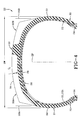
- the pneumatic tire 20 has a carcass 21 having one or more carcass plies 22 extending circumferentially about the axis of rotation of the tire 20.
- the carcass plies 22 are anchored around a pair of substantially inextensible annular beads 24.
- a belt or breaker reinforcing structure 26 comprising one or more belt or breaker plies 28 can be disposed radially outwardly from the carcass plies 22.
- the belt or breaker plies 28 provide reinforcement for the crown region of the tire 20.
- a circumferentially extending tread portion 32 is located radially outwardly of the belt reinforcing structure 26.
- a sidewall portion 33 extends radially inwardly from each axial or lateral tread edge 33A, 33B of the tread to an annular bead portion 35 having the beads 24 located therein.
- the carcass plies 22 preferably have textile or synthetic cords 22A reinforcing the plies 22.
- the cords 22A are preferably oriented radially in a single ply tire or if multiple plies are used then bias cords are employed. Most preferably, the cords 22A are made of polyester or nylon material.
- the tire 20 may have two to up to ten plies 22, each construction increasing in load carry capability as a function of the number of plies.
- the belt or breaker reinforcement structure 26 if used preferably includes at least two belts 28 reinforced by synthetic cords of rayon or aramid.
- the tire 20 according to the present invention has a unique tread 32.
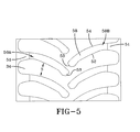
- the tread 32 has a first lateral tread edge 33A and a second lateral tread edge 33B. Disposed between the tread edges 33A, 33B is an inner tread 34 and a plurality of lugs 50 arranged in two rows 50A and 50B extending radially outwardly from the inner tread 34.
- the tread 32 is divided into two tread halves 32A and 32B, respectively.
- each lug 50 has a radially outer surface 58, a leading edge 52, trailing edge 54 and a centerline 63 between the leading and trailing edges.
- Each lug 50 in rows 50A and 50B extends generally axially inwardly from an axially outer end 51 to an axially inner end 53.
- Each lug 50 intersects the equatorial plane EP along the lug wall of the axially inner end 53 and has an orientation substantially offset circumferentially with the lugs 50 of the opposite row as shown.
- the radially outer surface 58 when viewed from the contact patch has a polygonal shape.
- the surface 58 exhibits the approximate orientation of the lug 50.
- the centerline 63 of the lugs is approximated by a line extending substantially parallel to the leading and trailing edges 52,54 and being generally equidistanced between these edges.
- the lugs have a length (I l ) at least three times their width (I w ) whereas block elements have a width greater than one-third the length of the element.
- a lug for purposes of this invention has preferably a length (I l ) at least 10% of the section width (SW) of the tire 20.
- the distance along the centerline 63 between the axially outer and inner ends 51,53 defines the length (I l ) of the lug 50.
- the distance extending substantially perpendicularly between the leading and trailing edges 52,54 of the lug define the lug width (I w ).
- the radial distance extending between the inner tread 34 and the edges 52,54 of the lug 50 defines the radial lug height (I h ).
- the ratio of the lug width (I w ) to lug radial heights (I h ) is equal to or greater than 1.0 over at least 70% of the lug length (I l ).
- the tire 20 has a very high net-to-gross ratio when compared to conventional farm tires. This is due in part to the wide surface area 58 of the lug 50 and the very large lug head 55 projecting from the leading edge 52 of the lug 50.
- the tire of the present invention adds at least four lugs, six in some size tires.
- the lugs 50 as shown in Figures 3 and 5 have a line K extending between a midpoint of the axially inner end 53 and a midpoint of the circumferentially extending axially outer end 51.
- the line K is oriented at an angle ß of 35° or less relative to the axial direction, as illustrated 31°.
- the spacing S between the adjacent lugs 50 within a row 50A or 50B and the inner tread 34 defines a soil discharge channel 70.
- Tires designed for good mud traction have the distance between lugs at least 4 times the lug width (I w ).
- the tire of the present invention has been designed to have this lug spacing distance reduced to less than three times the lug width (I w ), as shown 2.6 times. This greatly reduced channel width is possible because farmers avoid harvesting wet crops. Accordingly the stubble and the dry soil conditions enabled the tire 20 of the present invention to be designed with wide closely spaced lugs 50.
- the resultant net-to-gross ratio falls in the range of 29% to 35%, as illustrated about 29.5%.
- the combine tires typically are made in two bias tire sizes, a 24.5-32 (24.5 R 32 for radial) and a 30.5 L-32 (30.5 LR32 for radial) or the metric equivalent thereof.
- the total number of tread lugs in the 24.5-32 tire is proportional to the 30.5L-32 and in the 30.5L-32 tire fifty lugs are used. This amounts to at least two more lugs than the prior art tires.
Landscapes
- Engineering & Computer Science (AREA)
- Mechanical Engineering (AREA)
- Tires In General (AREA)
Abstract
Description
Claims (6)
- A drive axle tire (20) having a carcass (21) reinforced by at least one cord reinforced ply (22) and a tread (32) having a plurality of tread lugs (50), the tire being characterized by:the tread lugs (50) being arranged in two circumferentially offset rows (50A, 50B), a first row (50A) extending from a first shoulder toward the centerplane of the tread (32) but not crossing said centerplane, a second row (50B) extending from an opposite shoulder toward the centerplane of the tread (32) but not crossing said centerplane, each tread lug (50) of said first row (50A) being similar in shape and a mirror image of the tread lugs (50) of the second row (50B); wherein each lug (50) has a minimum width (Iw) as measured between a leading edge (52) and a trailing edge (54) of the lug (50), a lug length (Iw) as measured along a centerline of the lug (50) midway between the leading edge (52) and the trailing edge (54), and an average radial height (Ih) as measured from the non-skid surface to the radially outermost surface of the lug (50) and wherein the minimum lug width (Iw) is greater than or equal the average radial height (Ih) and the circumferential distance between the leading edge (52) and the trailing edge (54) of adjacent lugs (50) within each row is less than or equal to 3 times (Iw).
- The tire of claim 1 wherein the axially inner end (53) of each lug (50) has an enlarged lug head (55) projecting from the leading edge (52).
- The tire of claim 1 or 2 wherein each lug (50) has a circumferentially extending axially outer end (51) and an inclined axially inner end (53) oriented at an angle relative to the centerplane, being in the range of 30° to 60°.
- The tire of claim 3 wherein a line (K) drawn between midpoints of the axially outer end (51) and the axially inner end (53) is oriented at an angle (ß) of less than 35° to the axial direction.
- The tire of claim 4 wherein the line (K) is oriented at an angle (ß) of 31 °.
- The tire of at least one of the preceding claims wherein the tire size is 30.5L-32 and the total of lugs (50) number fifty around the circumference of the tire (20).
Applications Claiming Priority (2)
| Application Number | Priority Date | Filing Date | Title |
|---|---|---|---|
| US10/305,758 US20040099359A1 (en) | 2002-11-26 | 2002-11-26 | Agricultural combine tire |
| US305758 | 2002-11-26 |
Publications (3)
| Publication Number | Publication Date |
|---|---|
| EP1424220A2 true EP1424220A2 (en) | 2004-06-02 |
| EP1424220A3 EP1424220A3 (en) | 2004-11-03 |
| EP1424220B1 EP1424220B1 (en) | 2008-05-21 |
Family
ID=32298065
Family Applications (1)
| Application Number | Title | Priority Date | Filing Date |
|---|---|---|---|
| EP03104307A Expired - Lifetime EP1424220B1 (en) | 2002-11-26 | 2003-11-21 | Agricultural tire |
Country Status (5)
| Country | Link |
|---|---|
| US (1) | US20040099359A1 (en) |
| EP (1) | EP1424220B1 (en) |
| AU (1) | AU2003262212A1 (en) |
| BR (1) | BR0305293A (en) |
| DE (1) | DE60321112D1 (en) |
Families Citing this family (10)
| Publication number | Priority date | Publication date | Assignee | Title |
|---|---|---|---|---|
| US20040118497A1 (en) * | 2002-12-20 | 2004-06-24 | The Goodyear Tire & Rubber Company | Pneumatic tire for use on row-crop field sprayers and other like farm machinery |
| US9108469B2 (en) | 2007-10-01 | 2015-08-18 | Bridgestone Americas Tire Operations, Llc | Irrigation tire |
| USD612799S1 (en) | 2008-02-07 | 2010-03-30 | Bridgestone Americas Tire Operations, Llc | Tire tread |
| USD610072S1 (en) | 2008-06-06 | 2010-02-16 | Bridgestone Americas Tire Operations, Llc | Tire tread |
| FR2975635B1 (en) * | 2011-05-25 | 2013-05-24 | Michelin Soc Tech | PNEUMATIC TIRE TREAD FOR AGRICULTURAL TRACTOR |
| US8905097B2 (en) | 2012-02-01 | 2014-12-09 | Bridgestone Americas Tire Operations, Llc | Agricultural tire tread |
| US9522575B2 (en) | 2012-02-21 | 2016-12-20 | Bridgestone Americas Tire Operations, Llc | Agricultural bar nose to prevent stubble damage |
| US20130340906A1 (en) * | 2012-06-26 | 2013-12-26 | Bradley J. Harris | D speed agriculture tires |
| CN106827941B (en) * | 2016-12-20 | 2023-06-16 | 平湖市专博先进技术与转化研究院 | A wheel for a stroller |
| USD1047308S1 (en) * | 2023-12-08 | 2024-10-15 | Weiping He | Toy tire |
Family Cites Families (14)
| Publication number | Priority date | Publication date | Assignee | Title |
|---|---|---|---|---|
| US2065697A (en) * | 1936-02-20 | 1936-12-29 | Paul E Hawkinson | Tire tread |
| US2113527A (en) * | 1937-12-28 | 1938-04-05 | Firestone Tire & Rubber Co | Tire construction |
| FR1063458A (en) * | 1952-09-19 | 1954-05-04 | Non-slip tread for automobile or other car tires | |
| IT1038394B (en) * | 1975-05-22 | 1979-11-20 | Pirelli | IMPROVEMENT OF TIRES FOR AGRICULTURAL AND INDUSTRIAL VEHICLES |
| FR2511952A1 (en) * | 1981-08-31 | 1983-03-04 | Kleber Colombes | TIRE FOR AN AGRICULTURAL TRACTOR DRIVE WHEEL OR SIMILAR VEHICLE |
| JPS5911902A (en) * | 1982-07-09 | 1984-01-21 | Toyo Tire & Rubber Co Ltd | Pneumatic tire |
| US4534392A (en) * | 1984-05-16 | 1985-08-13 | The Goodyear Tire & Rubber Company | Tractor tire |
| US5337816A (en) * | 1992-11-20 | 1994-08-16 | The Goodyear Tire & Rubber Company | Pneumatic agricultural tire |
| US5411067A (en) * | 1993-03-23 | 1995-05-02 | The Goodyear Tire & Rubber Company | Pneumatic tire for use on agricultural tractors and other like vehicles |
| BR9602184A (en) * | 1995-05-19 | 1998-04-07 | Goodyear Tire & Rubber | Agricultural tire having a radial canvas carcass, a geometric axis of rotation and an annular tread |
| US6062282A (en) * | 1997-04-25 | 2000-05-16 | The Goodyear Tire & Rubber Company | Asymmetric directional pneumatic agricultural tire |
| JP3860306B2 (en) * | 1997-09-17 | 2006-12-20 | 株式会社ブリヂストン | Agricultural pneumatic tire with directional lugs |
| USD402245S (en) * | 1997-09-22 | 1998-12-08 | The Goodyear Tire & Rubber Company | Tread for a tire |
| US6209602B1 (en) * | 1999-02-03 | 2001-04-03 | The Goodyear Tire & Rubber Company | Industrial service agricultural tire |
-
2002
- 2002-11-26 US US10/305,758 patent/US20040099359A1/en not_active Abandoned
-
2003
- 2003-11-12 AU AU2003262212A patent/AU2003262212A1/en not_active Abandoned
- 2003-11-14 BR BR0305293-1A patent/BR0305293A/en not_active IP Right Cessation
- 2003-11-21 DE DE60321112T patent/DE60321112D1/en not_active Expired - Lifetime
- 2003-11-21 EP EP03104307A patent/EP1424220B1/en not_active Expired - Lifetime
Also Published As
| Publication number | Publication date |
|---|---|
| EP1424220B1 (en) | 2008-05-21 |
| BR0305293A (en) | 2004-08-31 |
| DE60321112D1 (en) | 2008-07-03 |
| AU2003262212A1 (en) | 2004-06-17 |
| US20040099359A1 (en) | 2004-05-27 |
| EP1424220A3 (en) | 2004-11-03 |
Similar Documents
| Publication | Publication Date | Title |
|---|---|---|
| EP0691221B1 (en) | A non-directional pneumatic tire for use on agricultural tractors and other like vehicles | |
| EP0552664B1 (en) | Improved agricultural tire | |
| US6263933B1 (en) | Industrial service agricultural tire | |
| AU714844B2 (en) | A pneumatic agricultural tire | |
| EP0423058B1 (en) | A tractor tire | |
| EP0795427A1 (en) | A pneumatic agricultural tire | |
| US5027876A (en) | Environmental tire | |
| US20100243118A1 (en) | Pneumatic tire for use on row-crop field sprayers and other like farm machinery | |
| US6209602B1 (en) | Industrial service agricultural tire | |
| EP1424220B1 (en) | Agricultural tire | |
| EP1544000B1 (en) | Low net to gross off-the-road tire | |
| US6450221B1 (en) | Non-directional farm tire | |
| US6481479B1 (en) | High aspect agricultural or off-road tire | |
| US6062282A (en) | Asymmetric directional pneumatic agricultural tire | |
| US7503360B2 (en) | Radial farm tire for high clearance sprayers | |
| EP1214204B1 (en) | Farm implement tire | |
| EP0958151A1 (en) | Industrial service agricultural tire | |
| EP1017574B1 (en) | High aspect agricultural or off-road tire | |
| EP0921955B1 (en) | Industrial service agricultural tire | |
| US6655430B1 (en) | Low pressure tire with a low angle restrictor belt | |
| EP1064158B1 (en) | Non-directional farm tire | |
| EP1021305A1 (en) | Asymmetric directional pneumatic agricultural tire | |
| MXPA99007089A (en) | Industrial service agricultural tire |
Legal Events
| Date | Code | Title | Description |
|---|---|---|---|
| PUAI | Public reference made under article 153(3) epc to a published international application that has entered the european phase |
Free format text: ORIGINAL CODE: 0009012 |
|
| AK | Designated contracting states |
Kind code of ref document: A2 Designated state(s): AT BE BG CH CY CZ DE DK EE ES FI FR GB GR HU IE IT LI LU MC NL PT RO SE SI SK TR |
|
| AX | Request for extension of the european patent |
Extension state: AL LT LV MK |
|
| PUAL | Search report despatched |
Free format text: ORIGINAL CODE: 0009013 |
|
| AK | Designated contracting states |
Kind code of ref document: A3 Designated state(s): AT BE BG CH CY CZ DE DK EE ES FI FR GB GR HU IE IT LI LU MC NL PT RO SE SI SK TR |
|
| AX | Request for extension of the european patent |
Extension state: AL LT LV MK |
|
| 17P | Request for examination filed |
Effective date: 20050503 |
|
| AKX | Designation fees paid |
Designated state(s): DE FR GB |
|
| GRAP | Despatch of communication of intention to grant a patent |
Free format text: ORIGINAL CODE: EPIDOSNIGR1 |
|
| RIC1 | Information provided on ipc code assigned before grant |
Ipc: B60C 11/11 20060101AFI20071108BHEP |
|
| GRAS | Grant fee paid |
Free format text: ORIGINAL CODE: EPIDOSNIGR3 |
|
| GRAA | (expected) grant |
Free format text: ORIGINAL CODE: 0009210 |
|
| AK | Designated contracting states |
Kind code of ref document: B1 Designated state(s): DE FR GB |
|
| REG | Reference to a national code |
Ref country code: GB Ref legal event code: FG4D |
|
| REF | Corresponds to: |
Ref document number: 60321112 Country of ref document: DE Date of ref document: 20080703 Kind code of ref document: P |
|
| PLBE | No opposition filed within time limit |
Free format text: ORIGINAL CODE: 0009261 |
|
| STAA | Information on the status of an ep patent application or granted ep patent |
Free format text: STATUS: NO OPPOSITION FILED WITHIN TIME LIMIT |
|
| 26N | No opposition filed |
Effective date: 20090224 |
|
| GBPC | Gb: european patent ceased through non-payment of renewal fee |
Effective date: 20081121 |
|
| PG25 | Lapsed in a contracting state [announced via postgrant information from national office to epo] |
Ref country code: GB Free format text: LAPSE BECAUSE OF NON-PAYMENT OF DUE FEES Effective date: 20081121 |
|
| PGFP | Annual fee paid to national office [announced via postgrant information from national office to epo] |
Ref country code: DE Payment date: 20141201 Year of fee payment: 12 Ref country code: FR Payment date: 20141027 Year of fee payment: 12 |
|
| REG | Reference to a national code |
Ref country code: DE Ref legal event code: R119 Ref document number: 60321112 Country of ref document: DE |
|
| REG | Reference to a national code |
Ref country code: FR Ref legal event code: ST Effective date: 20160729 |
|
| PG25 | Lapsed in a contracting state [announced via postgrant information from national office to epo] |
Ref country code: DE Free format text: LAPSE BECAUSE OF NON-PAYMENT OF DUE FEES Effective date: 20160601 |
|
| PG25 | Lapsed in a contracting state [announced via postgrant information from national office to epo] |
Ref country code: FR Free format text: LAPSE BECAUSE OF NON-PAYMENT OF DUE FEES Effective date: 20151130 |