EP1424180A1 - Method and system for removing metal wire in tire through induction heating - Google Patents
Method and system for removing metal wire in tire through induction heating Download PDFInfo
- Publication number
- EP1424180A1 EP1424180A1 EP02705318A EP02705318A EP1424180A1 EP 1424180 A1 EP1424180 A1 EP 1424180A1 EP 02705318 A EP02705318 A EP 02705318A EP 02705318 A EP02705318 A EP 02705318A EP 1424180 A1 EP1424180 A1 EP 1424180A1
- Authority
- EP
- European Patent Office
- Prior art keywords
- tire
- bead
- wires
- metal wires
- rubber
- Prior art date
- Legal status (The legal status is an assumption and is not a legal conclusion. Google has not performed a legal analysis and makes no representation as to the accuracy of the status listed.)
- Granted
Links
Images







Classifications
-
- B—PERFORMING OPERATIONS; TRANSPORTING
- B26—HAND CUTTING TOOLS; CUTTING; SEVERING
- B26D—CUTTING; DETAILS COMMON TO MACHINES FOR PERFORATING, PUNCHING, CUTTING-OUT, STAMPING-OUT OR SEVERING
- B26D3/00—Cutting work characterised by the nature of the cut made; Apparatus therefor
- B26D3/003—Cutting work characterised by the nature of the cut made; Apparatus therefor specially adapted for cutting rubber
- B26D3/005—Cutting work characterised by the nature of the cut made; Apparatus therefor specially adapted for cutting rubber for cutting used tyres
-
- B—PERFORMING OPERATIONS; TRANSPORTING
- B29—WORKING OF PLASTICS; WORKING OF SUBSTANCES IN A PLASTIC STATE IN GENERAL
- B29B—PREPARATION OR PRETREATMENT OF THE MATERIAL TO BE SHAPED; MAKING GRANULES OR PREFORMS; RECOVERY OF PLASTICS OR OTHER CONSTITUENTS OF WASTE MATERIAL CONTAINING PLASTICS
- B29B17/00—Recovery of plastics or other constituents of waste material containing plastics
- B29B17/02—Separating plastics from other materials
- B29B17/0206—Selectively separating reinforcements from matrix material by destroying the interface bound before disintegrating the matrix to particles or powder, e.g. from tires or belts
- B29B17/021—Selectively separating reinforcements from matrix material by destroying the interface bound before disintegrating the matrix to particles or powder, e.g. from tires or belts using local heating of the reinforcement
-
- B—PERFORMING OPERATIONS; TRANSPORTING
- B29—WORKING OF PLASTICS; WORKING OF SUBSTANCES IN A PLASTIC STATE IN GENERAL
- B29B—PREPARATION OR PRETREATMENT OF THE MATERIAL TO BE SHAPED; MAKING GRANULES OR PREFORMS; RECOVERY OF PLASTICS OR OTHER CONSTITUENTS OF WASTE MATERIAL CONTAINING PLASTICS
- B29B17/00—Recovery of plastics or other constituents of waste material containing plastics
- B29B17/04—Disintegrating plastics, e.g. by milling
- B29B17/0412—Disintegrating plastics, e.g. by milling to large particles, e.g. beads, granules, flakes, slices
-
- B—PERFORMING OPERATIONS; TRANSPORTING
- B29—WORKING OF PLASTICS; WORKING OF SUBSTANCES IN A PLASTIC STATE IN GENERAL
- B29C—SHAPING OR JOINING OF PLASTICS; SHAPING OF MATERIAL IN A PLASTIC STATE, NOT OTHERWISE PROVIDED FOR; AFTER-TREATMENT OF THE SHAPED PRODUCTS, e.g. REPAIRING
- B29C35/00—Heating, cooling or curing, e.g. crosslinking or vulcanising; Apparatus therefor
- B29C35/02—Heating or curing, e.g. crosslinking or vulcanizing during moulding, e.g. in a mould
- B29C35/08—Heating or curing, e.g. crosslinking or vulcanizing during moulding, e.g. in a mould by wave energy or particle radiation
- B29C35/0805—Heating or curing, e.g. crosslinking or vulcanizing during moulding, e.g. in a mould by wave energy or particle radiation using electromagnetic radiation
- B29C2035/0811—Heating or curing, e.g. crosslinking or vulcanizing during moulding, e.g. in a mould by wave energy or particle radiation using electromagnetic radiation using induction
-
- B—PERFORMING OPERATIONS; TRANSPORTING
- B29—WORKING OF PLASTICS; WORKING OF SUBSTANCES IN A PLASTIC STATE IN GENERAL
- B29K—INDEXING SCHEME ASSOCIATED WITH SUBCLASSES B29B, B29C OR B29D, RELATING TO MOULDING MATERIALS OR TO MATERIALS FOR MOULDS, REINFORCEMENTS, FILLERS OR PREFORMED PARTS, e.g. INSERTS
- B29K2021/00—Use of unspecified rubbers as moulding material
-
- B—PERFORMING OPERATIONS; TRANSPORTING
- B29—WORKING OF PLASTICS; WORKING OF SUBSTANCES IN A PLASTIC STATE IN GENERAL
- B29K—INDEXING SCHEME ASSOCIATED WITH SUBCLASSES B29B, B29C OR B29D, RELATING TO MOULDING MATERIALS OR TO MATERIALS FOR MOULDS, REINFORCEMENTS, FILLERS OR PREFORMED PARTS, e.g. INSERTS
- B29K2705/00—Use of metals, their alloys or their compounds, for preformed parts, e.g. for inserts
- B29K2705/08—Transition metals
- B29K2705/12—Iron
-
- B—PERFORMING OPERATIONS; TRANSPORTING
- B29—WORKING OF PLASTICS; WORKING OF SUBSTANCES IN A PLASTIC STATE IN GENERAL
- B29L—INDEXING SCHEME ASSOCIATED WITH SUBCLASS B29C, RELATING TO PARTICULAR ARTICLES
- B29L2030/00—Pneumatic or solid tyres or parts thereof
-
- Y—GENERAL TAGGING OF NEW TECHNOLOGICAL DEVELOPMENTS; GENERAL TAGGING OF CROSS-SECTIONAL TECHNOLOGIES SPANNING OVER SEVERAL SECTIONS OF THE IPC; TECHNICAL SUBJECTS COVERED BY FORMER USPC CROSS-REFERENCE ART COLLECTIONS [XRACs] AND DIGESTS
- Y02—TECHNOLOGIES OR APPLICATIONS FOR MITIGATION OR ADAPTATION AGAINST CLIMATE CHANGE
- Y02P—CLIMATE CHANGE MITIGATION TECHNOLOGIES IN THE PRODUCTION OR PROCESSING OF GOODS
- Y02P70/00—Climate change mitigation technologies in the production process for final industrial or consumer products
- Y02P70/10—Greenhouse gas [GHG] capture, material saving, heat recovery or other energy efficient measures, e.g. motor control, characterised by manufacturing processes, e.g. for rolling metal or metal working
-
- Y—GENERAL TAGGING OF NEW TECHNOLOGICAL DEVELOPMENTS; GENERAL TAGGING OF CROSS-SECTIONAL TECHNOLOGIES SPANNING OVER SEVERAL SECTIONS OF THE IPC; TECHNICAL SUBJECTS COVERED BY FORMER USPC CROSS-REFERENCE ART COLLECTIONS [XRACs] AND DIGESTS
- Y02—TECHNOLOGIES OR APPLICATIONS FOR MITIGATION OR ADAPTATION AGAINST CLIMATE CHANGE
- Y02W—CLIMATE CHANGE MITIGATION TECHNOLOGIES RELATED TO WASTEWATER TREATMENT OR WASTE MANAGEMENT
- Y02W30/00—Technologies for solid waste management
- Y02W30/50—Reuse, recycling or recovery technologies
- Y02W30/62—Plastics recycling; Rubber recycling
-
- Y—GENERAL TAGGING OF NEW TECHNOLOGICAL DEVELOPMENTS; GENERAL TAGGING OF CROSS-SECTIONAL TECHNOLOGIES SPANNING OVER SEVERAL SECTIONS OF THE IPC; TECHNICAL SUBJECTS COVERED BY FORMER USPC CROSS-REFERENCE ART COLLECTIONS [XRACs] AND DIGESTS
- Y10—TECHNICAL SUBJECTS COVERED BY FORMER USPC
- Y10S—TECHNICAL SUBJECTS COVERED BY FORMER USPC CROSS-REFERENCE ART COLLECTIONS [XRACs] AND DIGESTS
- Y10S156/00—Adhesive bonding and miscellaneous chemical manufacture
- Y10S156/934—Apparatus having delaminating means adapted for delaminating a specified article
- Y10S156/935—Delaminating means in preparation for post consumer recycling
- Y10S156/939—Means for delaminating vehicle component, e.g. tread from carcass, brake pad
-
- Y—GENERAL TAGGING OF NEW TECHNOLOGICAL DEVELOPMENTS; GENERAL TAGGING OF CROSS-SECTIONAL TECHNOLOGIES SPANNING OVER SEVERAL SECTIONS OF THE IPC; TECHNICAL SUBJECTS COVERED BY FORMER USPC CROSS-REFERENCE ART COLLECTIONS [XRACs] AND DIGESTS
- Y10—TECHNICAL SUBJECTS COVERED BY FORMER USPC
- Y10T—TECHNICAL SUBJECTS COVERED BY FORMER US CLASSIFICATION
- Y10T156/00—Adhesive bonding and miscellaneous chemical manufacture
- Y10T156/11—Methods of delaminating, per se; i.e., separating at bonding face
- Y10T156/1153—Temperature change for delamination [e.g., heating during delaminating, etc.]
-
- Y—GENERAL TAGGING OF NEW TECHNOLOGICAL DEVELOPMENTS; GENERAL TAGGING OF CROSS-SECTIONAL TECHNOLOGIES SPANNING OVER SEVERAL SECTIONS OF THE IPC; TECHNICAL SUBJECTS COVERED BY FORMER USPC CROSS-REFERENCE ART COLLECTIONS [XRACs] AND DIGESTS
- Y10—TECHNICAL SUBJECTS COVERED BY FORMER USPC
- Y10T—TECHNICAL SUBJECTS COVERED BY FORMER US CLASSIFICATION
- Y10T156/00—Adhesive bonding and miscellaneous chemical manufacture
- Y10T156/11—Methods of delaminating, per se; i.e., separating at bonding face
- Y10T156/1168—Gripping and pulling work apart during delaminating
- Y10T156/1189—Gripping and pulling work apart during delaminating with shearing during delaminating
-
- Y—GENERAL TAGGING OF NEW TECHNOLOGICAL DEVELOPMENTS; GENERAL TAGGING OF CROSS-SECTIONAL TECHNOLOGIES SPANNING OVER SEVERAL SECTIONS OF THE IPC; TECHNICAL SUBJECTS COVERED BY FORMER USPC CROSS-REFERENCE ART COLLECTIONS [XRACs] AND DIGESTS
- Y10—TECHNICAL SUBJECTS COVERED BY FORMER USPC
- Y10T—TECHNICAL SUBJECTS COVERED BY FORMER US CLASSIFICATION
- Y10T156/00—Adhesive bonding and miscellaneous chemical manufacture
- Y10T156/19—Delaminating means
- Y10T156/1961—Severing delaminating means [e.g., chisel, etc.]
- Y10T156/1967—Cutting delaminating means
- Y10T156/1972—Shearing delaminating means
Definitions
- the present invention relates to a method of removing metal wires from a tire using dielectric heating, a method of collecting the metal wires and rubber part of the tire, and a method of reusing the tire used in these methods. More specifically, the present invention relates to a method in which the metal wires in a tire are heated using electromagnetic induction, whereby the characteristic of the rubber of the part contacting the metal wires alters to separate the metal wires and rubber part, and thus the metal wires arranged in the tire are separated, collected, and reused. In particular, the present invention relates to a technique for recycling an automobile tire.
- a sidewall part 2 in which no steel wires are incorporated can be cut or shredded and reused. Further, the sidewall portion constitutes less than 30% of the entire tire.
- the parts incorporated with steel wires, or in other words the remaining 70%, are used as fuel for cement firing or metal smelting, for example.
- the present inventors considered the background art described above and performed various investigations with the object of developing a new method of removing metal wires in which the steel wires in a used tire can be separated and collected efficiently and by a simple operation.
- the present inventors it was discovered that by heating the metal wires in the tire using induction heating, the rubber of the part which contacts the metal wires is decomposed and gasified, whereby the metal wires and rubber part can be easily separated and collected.
- the present invention reached completion.
- An object of the present invention is to provide a method of separating and collecting metal wires from a tire using electromagnetic induction heating.
- a further object of the present invention is to provide a method of collecting the metal wires and rubber part of a tire using the method described above, and a method of reusing the metal wires and rubber part collected using the method described above as metal and rubber resources.
- a metal wire-incorporated tire in which metal wires such as steel wires are arranged and incorporated throughout the tire, and more particularly an automobile tire, is used as a subject, although there are no particular limitations on the type of tire.
- the metal wires are removed from the metal wire-incorporated tire using induction heating.
- induction heating a method of implementing induction heating in which the tire is cut in advance into a plurality of parts comprising parts having metal wires and parts not having metal wires is preferably employed.
- the tire is preferably cut into a bead portion, a sidewall portion, and a tread portion, but there are no particular limitations on the parts to be cut.
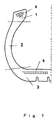
- a tire is cut into a bead portion 1, a sidewall portion 2, and a tread portion 3 using a cutter.
- the part of the tire to be used in the removal of the steel wires 4 is the tread portion.
- the steel wires are arranged in two lines in the tread portion.
- a high frequency coil 5 is disposed on the outside of the tread portion of the severed tire, and thus the steel wires are heated by induction heating.
- Steel wires and rubber can be separated according to the principle described above, and hence, by rotating the tread portion on the circumference under the high frequency coil, for example, the steel wires in the tire can be completely separated from the rubber part by a simple operation.
- the metal wires and rubber part of the tire can be collected at a high collection rate, and furthermore, the collected metal wires and rubber part can be reused and recycled as metal and rubber resources, high value added fuel, and so on.
- the tire is cut along the circumferential direction thereof using cutting means such as a cutter, and thereby divided into the tread portion and a part comprising the bead portion.
- the tire is preferably divided into three parts, the tread portion, the sidewall portion, and the bead portion.
- the part in question is the part comprising the bead portion, or in other words the sidewall portion and bead portion.
- This part has a substantially disk-form shape with a large hole in the center.
- the dividing operation may be performed as desired, and the cutting position need only be rough. It goes without saying that the dividing operation may be performed using means which cut by shearing or the like rather than a cutter.
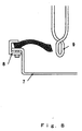
- the disk form sidewall portion and bead portion are placed on fixing means, for example a disk 7 which rotates on a horizontal plane, and fixed to the rotary disk by a clamp 8.
- a method of fixing the end portion of the sidewall portion such as that shown in Fig. 8, for example, is preferably provided, but the present invention is not limited to the example shown in Fig. 8.
- the fixing means are not limited to the rotary disk described above, and as long as a similar function is exhibited, there are no particular limitations on the type of fixing means.
- other means such as an automatic clamp operated by oil pressure or the like may be used, for example.
- the bead wires are subjected to induction heating by the high frequency coil.
- the bead wires are preferably subjected to induction heating under conditions of 100 to 200°C, whereby the rubber contacting the bead wires decomposes, the air contained inside the rubber expands, and thus the rubber and wires are separated such that a gap forms around the bead wires, as shown in Fig. 9.
- latching means 10 having a forked hook, for example, are preferably hung down from above the tire such that the hook is inserted below the tire disk.
- a hook with a sharply pointed distal end is preferably used.
- the hook is moved upward such that the distal end of the hook pierces the bead portion or the sidewall portion near the bead portion. The hook is then moved further upward such that the hook contacts the bead wires.
- the end of the sidewall portion is fixed to the rotary disk, and thus by continuing to move the hook upward, the rubber portion covering the bead portion is cut into and torn away such that only the bead wires are picked up by the hook.
- the latching means having the hook described above are provided as a favorable example of the aforementioned latching means, but the latching means are not limited thereto, and any means that are capable of functioning similarly to cut away the rubber covering the bead portion, separate the bead wires from the bead portion, and collect the bead wires may be used in similar fashion.
- the subject of this example is the separation of the steel wires in the tread portion of the tire. Separation of the steel wires in the tread portion preferably begins with the division of the tire into three parts, the tread portion, sidewall portion, and bead portion, around the circumferential direction of the tire.
- the tread portion severed in this process takes a cylindrical ring form.
- the outside of this cylindrical ring will be referred to as an outer ground-contacting face 17, and the inside will be referred to as an inner face 18.
- the method of dividing the tire is not limited to the method described above, and any appropriate method for separating the part comprising the tread portion may be used.
- the cylindrical ring-form tread portion 11 is inverted such that the inner face 18 is turned outward and the outer ground-contacting face 17 is turned inward.
- the inverted, inside-out tread portion 11 is preferably fixed by being positioned on the outside of a large and small pair of rollers, as shown in Fig. 10.
- the large roller is directly connected to a driving mechanism such as a motor, and thus can be rotationally driven.
- This roller will be referred to as a driven roller 15.
- the small roller does not comprise a driving mechanism, but does comprise a mechanism enabling the small roller to move left and right. This roller will be referred to as a moving roller 16.
- the moving roller is moved in the rightward direction in the drawing so as to gently pull the cylindrical ring-form tread portion.
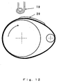
- the driven roller is caused to rotate slowly as shown in Fig. 12.
- a high frequency induction coil 19 is brought near to the rotating tread portion, whereby the steel wires buried in the tread portion are heated.
- an induction hardening device with a frequency of at least 50kHz and an output level of several tens of KW is used as the induction heating device.
- the present invention is not limited thereto, however, and any device which exhibits an equally effective induction heating performance may be used in similar fashion. Further, the shape of the heating coil is not limited.
- An appropriate method is employed as a method of heating the tread portion using the high frequency induction coil described above, for example a method in which the high frequency induction coil is fixed and the rotating tread portion is brought close, a method in which the tread portion is fixed to fixing means and the high frequency induction coil is brought close, or similar.
- the rubber which contacts the heated steel wires is decomposed and gasified, and the heating produces a part 20 which is dilated into balloon form.
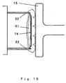
- a gap produced by the gasification of the rubber coalesces with the respective gaps produced around adjacent steel wires and swells into balloon form, thereby creating a cavity 21 as shown in Fig. 13.
- the rubber and the steel wires 14 of the tread portion 11 are separated.
- a cutter 22 attached to a cutter holder 23 is brought into contact with the tread portion such that the balloon portion is cut open and then cut away.
- the cutter 22 is preferably formed with cutters 22 on both sides of the cutter holder so as to be capable of cutting open both ends of the swollen inner face part of the tread portion simultaneously. In this case, there are no particular limitations on the number, formation position, and so on of the cutters.
- the inner face part that is cut away by the operation described above is removed, thus enabling the steel wires to be removed easily.
- by sweeping the surface of the inner face part using appropriate means such as a brush the steel wires can be easily separated from the tire.
- a tire was severed into a bead portion, a sidewall portion, and a tread portion, and the severed tread portion was subjected to induction heating using an induction hardening device with a frequency of 50kHz and a maximum output of 30kW.
- the high frequency output at this time was several kilowatts.
- the employed coil was a two winding flat induction hardening coil with a wire diameter ⁇ of 8mm and a coil diameter ⁇ of 100mm.
- the tread was then rotated directly beneath the heating coil at a circumferential velocity of 100m/sec.
- the induction heating caused the rubber of the part contacting the metal wires to decompose and gasify, whereby the metal wires and rubber part were separated.
- the part which dilated into balloon form due to the decomposition and gasification of the rubber was cut away, the metal wires and rubber part were extracted, and thus the metal wires and rubber part were separated and collected.
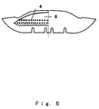
- Fig. 6 shows the result of induction heating applied to the extracted part of the tread portion.
- the employed high frequency was obtained by a device with a frequency of 50kHz and a maximum output of 30kw.
- gasification occurred from three to five seconds after the beginning of heat application, whereby the tread portion dilated into balloon form toward the inside of the tread portion.
- the temperature of the rubber part at this time which was measured by inserting a thermo couple into the rubber part near the steel wires, was 117°C, and it was learned that this is a temperature at which the rubber part other than the steel wires does not burn or change in nature due to the applied heat. In consideration of the heating period and applied power, it is believed that dilation into balloon form occurs at an extremely low input energy.
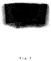
- Fig. 7 shows the interior of the part of the tread portion dilated into balloon form cut open and observed. As shown in the figure, the steel wires are arranged with almost no disturbance, and the rubber on the inside part of the tread has been peeled away easily and with no resistance. It goes without saying that the steel wires on the outside part of the tread are also completely separated.
- the steel wires can be easily retrieved.
- a tire of a normal passenger vehicle was cut in the circumferential direction thereof are divided into a tread portion, a sidewall portion, and a bead portion.
- the tire disk constituted by the sidewall portion and bead portion was placed on a disk, and the end portion of the sidewall portion was fixed by a clamp.
- the bead wires of the bead portion were subjected to induction heating using an induction hardening device with a frequency of 400KHz and a maximum output of 30kw.
- the high frequency output at this time was set to three kilowatts, and the disk on which the sidewall portion and bead portion were placed was rotated at a velocity of 3rpm.
- the bead wires of the bead portion were subjected to induction heating by positioning a high frequency coil in the vicinity of the bead portion.
- the rubber of the part contacting the bead wires was caused to decompose and gasify, whereby the bead wires and the rubber part were separated.
- a hook of latching means having a forked hook as shown in Fig. 9 was inserted below the tire disk, and by moving the hook upward, the distal end of the hook was caused to pierce the bead portion.
- the rubber portion covering the bead portion was torn away, whereupon the bead wires were extracted, and thus the bead wires and rubber part were separated and collected.
- the rubber part was then cut and shredded according to a normal method and reused as pavement material or the like.
- gasification of the rubber of the part contacting the bead wires occurs immediately after the beginning of induction heating of the bead wires, causing the bead portion to dilate into balloon form toward the inside of the bead portion.
- the temperature of the rubber part at this time which was measured by inserting a thermo couple into the rubber part near the bead wires, was 136°C, and it was learned that this is a temperature at which the rubber part other than the bead wires does not burn or change in nature due to the applied heat.
- the rubber of the inside part of the bead can be peeled away easily and with no resistance, enabling the bead wires to be extracted.
- the present invention relates to a method of removing metal wires from a tire by applying induction heating such that the metal wires in the tire are heated and the rubber of the part contacting the metal wires is decomposed and gasified, as a result of which the metal wires and rubber part separate and the metal wires can be removed.
- metal and rubber can be separated at high speed, low energy, without severing the steel wires using a cutter, and with an extremely small region of alteration in the obtained rubber;
- metal wires can be removed from a tire efficiently and by a simple operation;
- the metal wires and rubber portion of a used tire can be separated and collected at a high collection rate;
- the metal wires and rubber part collected from the used tire can be reused as metal and rubber resources.
Landscapes
- Engineering & Computer Science (AREA)
- Mechanical Engineering (AREA)
- Environmental & Geological Engineering (AREA)
- Life Sciences & Earth Sciences (AREA)
- Forests & Forestry (AREA)
- Separation, Recovery Or Treatment Of Waste Materials Containing Plastics (AREA)
- Processing Of Solid Wastes (AREA)
- General Induction Heating (AREA)
Abstract
Description
Claims (16)
- A metal wire removal method for removing metal wires from a tire incorporated with metal wires using induction heating, which comprises heating the metal wires in the tire by induction heating, thereby altering the characteristic of the rubber part contacting the metal wires of the tire to separate the metal wires and the rubber part, and then removing the metal wires therefrom.
- The metal wire removal method according to claim 1, wherein the tire is cut into a plurality of parts in advance, and the part of the tire incorporated with metal wires is heated by induction heating.
- The metal wire removal method according to claim 2, wherein the tire is cut into a bead portion, a sidewall portion, and a tread portion.
- The metal wire removal method according to claim 1, wherein the part of the tire incorporated with metal wires is the tread portion.
- The metal wire removal method according to claim 1, wherein a portion of the part of the tire which dilates due to decomposition and gasification is cut away, and the metal wires are extracted and removed from the cut-away portion.
- The metal wire removal method according to claim 1, wherein a high frequency coil is disposed on the inside or outside of the tire, and the rubber contacting the metal wires of the tire is caused to decompose and gasify through induction heating.
- A collection method for separating and collecting metal wires from a tire incorporated with metal wires using the method according to claim 1, which comprises heating the metal wires in the tire by induction heating, thereby altering the characteristic of the rubber part contacting the metal wires of the tire to separate the metal wires and the rubber part, and then collecting the metal wires and the rubber part therefrom.
- A tire recycling method characterized in that the metal wires and the rubber part collected using the method, according to claim 7 are reused as metal and rubber resources.
- A bead wire removal method characterized in that a sidewall portion and a bead portion separated from a tire are placed onto fixing means and fixed thereby, the bead wires in the bead portion are subjected to induction heating, the rubber covering the bead portion is cut away, and then the bead wires are separated from the bead portion.
- The bead wire removal method according to claim 9, wherein the sidewall portion and the bead portion are placed on a disk and fixed thereby, and then the bead wires in the bead portion are subjected to induction heating while the disk is rotated.
- The bead wire removal method according to claim 9, wherein the rubber portion covering the bead portion is latched by latching means to cut the rubber away, and then the bead wires are extracted from the bead portion.
- A bead wire removal device for removing bead wires from a tire comprising a bead portion, comprising:fixing means for fixing a tire comprising a bead portion by placing the tire comprising the bead portion thereon;induction heating means for heating the bead wires in the bead portion; andlatching means for latching the rubber portion covering the bead portion to separate the bead wires from the bead portion.
- A steel wire removal method for removing steel wires from a tread portion of a tire, comprising the steps of:(1) separating a part comprising the tread portion from the tire;(2) inverting the inner face and outer face of said tread portion such that said tread portion is turned inside out;(3) subjecting said inside-out tread portion to induction heating;(4) cutting open the part which is dilated by said induction heating; and(5) removing said steel wires.
- The method according to claim 13, wherein the inverted, inside-out tread portion is attached to a rotary drum or rotary roller, and is subjected to induction heating while said rotary drum or rotary roller is rotated.
- A steel wire removal device for removing steel wires from a tread portion of a tire, comprising as constitutional elements:(1) fixing means to which the inverted, inside-out tread portion is attached; and(2) induction heating means for induction heating said tread portion; and also comprising as optional means:(3) cutting means to cut open the part of said tread portion that is dilated by said heating; and(4) steel wire removal means to remove said steel wires.
- The device according to claim 15, wherein said fixing means comprise a rotary drum or a rotary roller.
Applications Claiming Priority (3)
| Application Number | Priority Date | Filing Date | Title |
|---|---|---|---|
| JP2001182547 | 2001-06-15 | ||
| JP2001182547A JP2002370227A (en) | 2001-06-15 | 2001-06-15 | Metal wire removal method from tire by induction heating |
| PCT/JP2002/002574 WO2002102563A1 (en) | 2001-06-15 | 2002-03-19 | Method and system for removing metal wire in tire through induction heating |
Publications (3)
| Publication Number | Publication Date |
|---|---|
| EP1424180A1 true EP1424180A1 (en) | 2004-06-02 |
| EP1424180A4 EP1424180A4 (en) | 2004-09-15 |
| EP1424180B1 EP1424180B1 (en) | 2006-07-19 |
Family
ID=19022635
Family Applications (1)
| Application Number | Title | Priority Date | Filing Date |
|---|---|---|---|
| EP20020705318 Expired - Lifetime EP1424180B1 (en) | 2001-06-15 | 2002-03-19 | Method and system for removing metal wire from tires through induction heating |
Country Status (6)
| Country | Link |
|---|---|
| US (1) | US6979384B2 (en) |
| EP (1) | EP1424180B1 (en) |
| JP (1) | JP2002370227A (en) |
| CN (1) | CN100374272C (en) |
| DE (1) | DE60213259T2 (en) |
| WO (1) | WO2002102563A1 (en) |
Cited By (1)
| Publication number | Priority date | Publication date | Assignee | Title |
|---|---|---|---|---|
| RU236885U1 (en) * | 2025-05-29 | 2025-08-28 | Кирилл Витальевич Чуев | Installation for removing the bead metal ring from the side of the tire |
Families Citing this family (14)
| Publication number | Priority date | Publication date | Assignee | Title |
|---|---|---|---|---|
| UA84945C2 (en) * | 2007-01-24 | 2008-12-10 | Григорий Абрамович Березин | method and device of utilization of TYREs |
| US20090117397A1 (en) * | 2007-11-01 | 2009-05-07 | Jose Manuel Ballina | Methods and apparatus for recycling tires and reinforcing rubber based products |
| EP2346934B1 (en) * | 2008-10-31 | 2015-01-14 | Rubreco Inc. | Separating devulcanized rubber |
| CZ305525B6 (en) * | 2010-05-13 | 2015-11-18 | EMG Zlín, s.r.o. | Optimized method of metal support separation from rubber-bonded metal composites and apparatus for making the same |
| US8863518B2 (en) | 2010-09-27 | 2014-10-21 | Saudi Arabian Oil Company | Process for the gasification of waste tires with residual oil |
| CN102861763A (en) * | 2012-10-10 | 2013-01-09 | 梅胜旺 | Winding wire rubber separator |
| JP6347964B2 (en) * | 2014-02-26 | 2018-06-27 | 株式会社ブリヂストン | Tire separation method |
| CZ2014336A3 (en) * | 2014-05-15 | 2016-05-04 | Football Pro S.R.O. | Recycling process of pneumatic tire containing steel cord fabric and apparatus for making the same |
| CN105482154A (en) * | 2015-12-16 | 2016-04-13 | 华东理工大学 | Method for recycling carbon fibers from carbon-fiber-enhanced high polymer material based on induction heating effect |
| EP3828339B1 (en) | 2016-04-05 | 2023-11-29 | FiberLean Technologies Limited | Paper and paperboard products |
| CN109622567A (en) * | 2018-12-25 | 2019-04-16 | 山东安途制动材料有限公司 | A kind of method that the steel back of disc brake pad waste product is separated with friction material |
| DE102019219082A1 (en) * | 2019-12-06 | 2021-06-10 | Continental Reifen Deutschland Gmbh | Process for recycling pneumatic vehicle tires with a sealant layer |
| AU2023369167B9 (en) | 2022-10-28 | 2025-08-07 | Flsmidth A/S | Method and apparatus for recycling composite mill liners |
| DE102023126384A1 (en) * | 2023-09-27 | 2025-03-27 | Giesecke+Devrient ePayments GmbH | Method and removal device for removing a wire from a portable data carrier and disposal system with removal device |
Family Cites Families (20)
| Publication number | Priority date | Publication date | Assignee | Title |
|---|---|---|---|---|
| US1459693A (en) * | 1923-06-19 | Canada | ||
| US1329239A (en) * | 1919-07-12 | 1920-01-27 | Edward P Hafner | Tire-peeling machine |
| US1869680A (en) * | 1928-12-22 | 1932-08-02 | Goodrich Co B F | Method and apparatus for removing treads from tires |
| US2230302A (en) * | 1935-11-20 | 1941-02-04 | Goodrich Co B F | Apparatus for removing bead cores from tires |
| US2291862A (en) * | 1942-04-24 | 1942-08-04 | Chrysler Corp | Removal of bonded rubber |
| US2636408A (en) * | 1949-03-28 | 1953-04-28 | Essex Wire Corp | Method of stripping insulated wire |
| JPS5334235B2 (en) * | 1972-12-25 | 1978-09-19 | ||
| JPS52114681A (en) * | 1976-03-23 | 1977-09-26 | Bridgestone Tire Co Ltd | Breaking method of waste tire |
| JPS59192548A (en) * | 1983-04-15 | 1984-10-31 | Hitachi Zosen Corp | How to remove steel cord from tires |
| JPS60203411A (en) * | 1984-03-28 | 1985-10-15 | High Frequency Heattreat Co Ltd | Peeling method of steel belt of steel tire |
| JPS6122613A (en) | 1984-07-10 | 1986-01-31 | 昭和電工株式会社 | Solid electrolytic condenser |
| JPS6122613U (en) * | 1984-07-17 | 1986-02-10 | 昇 山脇 | Steel cord separation device for waste tires |
| WO1991014554A1 (en) * | 1990-03-22 | 1991-10-03 | Odessky Gosudarstvenny Universitet | Method for extraction of metal reinforcement from rubber tyres |
| US5290380A (en) * | 1990-03-22 | 1994-03-01 | Alexandr Isaakovich Gitelman | Method for recovering breaker metal cord threads from tires |
| FR2676679B1 (en) * | 1991-05-23 | 1993-08-20 | Michelin & Cie | METHOD FOR SCRAPING TIRES, AND TRACK SPECIFICALLY DEVELOPED TO APPLY THIS PROCESS. |
| JP3405593B2 (en) * | 1994-04-28 | 2003-05-12 | 住友ゴム工業株式会社 | Disassembly method of metal / rubber composite |
| JP3405595B2 (en) * | 1994-05-17 | 2003-05-12 | 住友ゴム工業株式会社 | Disassembly method of metal / rubber composite |
| US5683038A (en) | 1995-12-06 | 1997-11-04 | Shinal; Thomas J. | Tire dissection system |
| US5783035A (en) * | 1997-01-21 | 1998-07-21 | Pederson; Les H. | Tire debeading machine |
| CN2321605Y (en) * | 1998-02-16 | 1999-06-02 | 宋学荣 | Steel wire tyre separating machine |
-
2001
- 2001-06-15 JP JP2001182547A patent/JP2002370227A/en active Pending
-
2002
- 2002-03-19 CN CNB028120272A patent/CN100374272C/en not_active Expired - Fee Related
- 2002-03-19 EP EP20020705318 patent/EP1424180B1/en not_active Expired - Lifetime
- 2002-03-19 US US10/479,984 patent/US6979384B2/en not_active Expired - Fee Related
- 2002-03-19 DE DE2002613259 patent/DE60213259T2/en not_active Expired - Lifetime
- 2002-03-19 WO PCT/JP2002/002574 patent/WO2002102563A1/en not_active Ceased
Cited By (1)
| Publication number | Priority date | Publication date | Assignee | Title |
|---|---|---|---|---|
| RU236885U1 (en) * | 2025-05-29 | 2025-08-28 | Кирилл Витальевич Чуев | Installation for removing the bead metal ring from the side of the tire |
Also Published As
| Publication number | Publication date |
|---|---|
| DE60213259D1 (en) | 2006-08-31 |
| EP1424180B1 (en) | 2006-07-19 |
| US20040168763A1 (en) | 2004-09-02 |
| DE60213259T2 (en) | 2007-06-14 |
| JP2002370227A (en) | 2002-12-24 |
| EP1424180A4 (en) | 2004-09-15 |
| WO2002102563A1 (en) | 2002-12-27 |
| CN100374272C (en) | 2008-03-12 |
| US6979384B2 (en) | 2005-12-27 |
| CN1531475A (en) | 2004-09-22 |
Similar Documents
| Publication | Publication Date | Title |
|---|---|---|
| US6979384B2 (en) | Method and system for removing metal wires in tire through induction heating | |
| US12129144B2 (en) | Solar panel cutting unit | |
| CA1083117A (en) | Method and apparatus for the recovery of vulcanised elastomeric material | |
| US5683038A (en) | Tire dissection system | |
| AU1972592A (en) | Method of reclaiming rubber from vehicle tyres | |
| CN106625876A (en) | Method for battery pole piece die cutting and circular cutter die cutting equipment | |
| EP0478774A1 (en) | Method for extraction of metal reinforcement from rubber tyres | |
| JP2003260437A (en) | Method and apparatus for separating composite member made of resin or rubber and metal | |
| US4184642A (en) | Apparatus for the recovery of vulcanized elastomeric material | |
| JP2000225617A (en) | Method and apparatus for treating used ST conveyor belt | |
| JP2004223801A (en) | Method and apparatus for removing metal wire in waste tire | |
| JP3924605B2 (en) | Method and apparatus for removing tire bead wire | |
| CN203600467U (en) | Automatic beverage bottle label stripping machine | |
| US20040173699A1 (en) | Tire recycling system and apparatus used therefor | |
| JP2001195934A (en) | System of separating cover from core wire of waste electrical wire or waste signal wire | |
| CN103144217A (en) | Steel and plastic separating and reusing treatment device of plastic-steel winding pipe and processing method thereof | |
| EP0477368A1 (en) | Method for extraction of breaker metal cords from tyres | |
| JP3870256B2 (en) | Steel wire removal method and apparatus for tread portion of waste tire | |
| RU2176952C1 (en) | Method for preparation of wheel tire to salvaging | |
| JP2023531550A (en) | METHOD AND APPLICATION UNIT FOR APPLYING SOUND ABSORBING MATERIAL TO BOUND OF PNEUMATIC TIRE | |
| KR100940518B1 (en) | Wire separation equipment of tier | |
| JPH08264047A (en) | Method of peeling coating material from coated electric wire | |
| CN219112487U (en) | Recycling machine for waste tires | |
| KR100593014B1 (en) | Bead-Apex Separator | |
| KR940008258B1 (en) | Stripping Device of Waste Wire Cover |
Legal Events
| Date | Code | Title | Description |
|---|---|---|---|
| PUAI | Public reference made under article 153(3) epc to a published international application that has entered the european phase |
Free format text: ORIGINAL CODE: 0009012 |
|
| 17P | Request for examination filed |
Effective date: 20040114 |
|
| AK | Designated contracting states |
Kind code of ref document: A1 Designated state(s): AT BE CH CY DE DK ES FI FR GB GR IE IT LI LU MC NL PT SE TR |
|
| AX | Request for extension of the european patent |
Extension state: AL LT LV MK RO SI |
|
| A4 | Supplementary search report drawn up and despatched |
Effective date: 20040802 |
|
| RIC1 | Information provided on ipc code assigned before grant |
Ipc: 7B 26D 1/00 B Ipc: 7B 29B 17/02 B Ipc: 7B 29B 17/00 A |
|
| 17Q | First examination report despatched |
Effective date: 20050315 |
|
| RTI1 | Title (correction) |
Free format text: METHOD AND SYSTEM FOR REMOVING METAL WIRE FROM TIRES THROUGH INDUCTION HEATING |
|
| GRAP | Despatch of communication of intention to grant a patent |
Free format text: ORIGINAL CODE: EPIDOSNIGR1 |
|
| GRAS | Grant fee paid |
Free format text: ORIGINAL CODE: EPIDOSNIGR3 |
|
| GRAA | (expected) grant |
Free format text: ORIGINAL CODE: 0009210 |
|
| AK | Designated contracting states |
Kind code of ref document: B1 Designated state(s): DE FR |
|
| REF | Corresponds to: |
Ref document number: 60213259 Country of ref document: DE Date of ref document: 20060831 Kind code of ref document: P |
|
| ET | Fr: translation filed | ||
| PLBE | No opposition filed within time limit |
Free format text: ORIGINAL CODE: 0009261 |
|
| STAA | Information on the status of an ep patent application or granted ep patent |
Free format text: STATUS: NO OPPOSITION FILED WITHIN TIME LIMIT |
|
| 26N | No opposition filed |
Effective date: 20070420 |
|
| PGFP | Annual fee paid to national office [announced via postgrant information from national office to epo] |
Ref country code: FR Payment date: 20120403 Year of fee payment: 11 |
|
| PGFP | Annual fee paid to national office [announced via postgrant information from national office to epo] |
Ref country code: DE Payment date: 20120323 Year of fee payment: 11 |
|
| REG | Reference to a national code |
Ref country code: FR Ref legal event code: ST Effective date: 20131129 |
|
| REG | Reference to a national code |
Ref country code: DE Ref legal event code: R119 Ref document number: 60213259 Country of ref document: DE Effective date: 20131001 |
|
| PG25 | Lapsed in a contracting state [announced via postgrant information from national office to epo] |
Ref country code: FR Free format text: LAPSE BECAUSE OF NON-PAYMENT OF DUE FEES Effective date: 20130402 Ref country code: DE Free format text: LAPSE BECAUSE OF NON-PAYMENT OF DUE FEES Effective date: 20131001 |