EP1424164A1 - Random orbital sander - Google Patents
Random orbital sander Download PDFInfo
- Publication number
- EP1424164A1 EP1424164A1 EP03025559A EP03025559A EP1424164A1 EP 1424164 A1 EP1424164 A1 EP 1424164A1 EP 03025559 A EP03025559 A EP 03025559A EP 03025559 A EP03025559 A EP 03025559A EP 1424164 A1 EP1424164 A1 EP 1424164A1
- Authority
- EP
- European Patent Office
- Prior art keywords
- sealing
- bearing
- clamping
- motor shaft
- annular
- Prior art date
- Legal status (The legal status is an assumption and is not a legal conclusion. Google has not performed a legal analysis and makes no representation as to the accuracy of the status listed.)
- Granted
Links
- 239000000428 dust Substances 0.000 claims abstract description 25
- 238000007789 sealing Methods 0.000 claims description 52
- 230000008878 coupling Effects 0.000 claims description 5
- 238000010168 coupling process Methods 0.000 claims description 5
- 238000005859 coupling reaction Methods 0.000 claims description 5
- 239000012530 fluid Substances 0.000 claims description 5
- 239000002245 particle Substances 0.000 description 9
- 238000010276 construction Methods 0.000 description 7
- 239000000463 material Substances 0.000 description 3
- 230000002093 peripheral effect Effects 0.000 description 3
- 239000000853 adhesive Substances 0.000 description 2
- 230000001070 adhesive effect Effects 0.000 description 2
- 238000001816 cooling Methods 0.000 description 2
- 230000000717 retained effect Effects 0.000 description 2
- 239000004677 Nylon Substances 0.000 description 1
- 238000005299 abrasion Methods 0.000 description 1
- 230000000712 assembly Effects 0.000 description 1
- 238000000429 assembly Methods 0.000 description 1
- 238000009434 installation Methods 0.000 description 1
- 150000002825 nitriles Chemical class 0.000 description 1
- 229920001778 nylon Polymers 0.000 description 1
- 229920000728 polyester Polymers 0.000 description 1
- 239000000126 substance Substances 0.000 description 1
Images



Classifications
-
- B—PERFORMING OPERATIONS; TRANSPORTING
- B24—GRINDING; POLISHING
- B24B—MACHINES, DEVICES, OR PROCESSES FOR GRINDING OR POLISHING; DRESSING OR CONDITIONING OF ABRADING SURFACES; FEEDING OF GRINDING, POLISHING, OR LAPPING AGENTS
- B24B23/00—Portable grinding machines, e.g. hand-guided; Accessories therefor
- B24B23/02—Portable grinding machines, e.g. hand-guided; Accessories therefor with rotating grinding tools; Accessories therefor
- B24B23/03—Portable grinding machines, e.g. hand-guided; Accessories therefor with rotating grinding tools; Accessories therefor the tool being driven in a combined movement
-
- B—PERFORMING OPERATIONS; TRANSPORTING
- B24—GRINDING; POLISHING
- B24B—MACHINES, DEVICES, OR PROCESSES FOR GRINDING OR POLISHING; DRESSING OR CONDITIONING OF ABRADING SURFACES; FEEDING OF GRINDING, POLISHING, OR LAPPING AGENTS
- B24B23/00—Portable grinding machines, e.g. hand-guided; Accessories therefor
- B24B23/02—Portable grinding machines, e.g. hand-guided; Accessories therefor with rotating grinding tools; Accessories therefor
- B24B23/026—Fluid driven
-
- B—PERFORMING OPERATIONS; TRANSPORTING
- B24—GRINDING; POLISHING
- B24B—MACHINES, DEVICES, OR PROCESSES FOR GRINDING OR POLISHING; DRESSING OR CONDITIONING OF ABRADING SURFACES; FEEDING OF GRINDING, POLISHING, OR LAPPING AGENTS
- B24B55/00—Safety devices for grinding or polishing machines; Accessories fitted to grinding or polishing machines for keeping tools or parts of the machine in good working condition
Definitions
- Random orbital sanders are well known and typically comprise a pneumatically operated motor having a casing suitably mounted within a manually manipulated housing and a balanced, motor shaft supported for rotation relative to the motor casing by uppermost and lowermost bearings; and a motor shaft mounted bearing serving to couple the motor shaft to a sanding pad or disc.
- Prior sanders of the type generally described are known to be subject to bearing failure resulting from the egress of dust particles thereinto during use.
- a lowermost motor shaft support bearing is particularly subject to failure resulting from its direct exposure to a dusty or sanding environment during use and the tendency for dust ladened air to be momentarily drawn upwardly therethrough towards the interior of the motor each time the motor is turned off.
- the uppermost motor support bearing is known to have a substantially longer useful operating life in that it is normally shielded from dust, due to its placement wholly within the confines of the housing of the sander.
- the motor shaft mounted bearing employed to couple the drive shaft to a sanding pad or disc is also know to be subject to failure due to the ingress of abrasive dust particles, and in commonly assigned U.S. Patent 4,854,085 there is described a dust seal having utility with this type of bearing.
- this dust seal has the disadvantage of being of multiple part construction.
- the present invention relates to seals particularly adapted to seal bearings of random orbital sanders against the egress of dust particles, such as would otherwise shorten the useful life of such sanders.
- a first of such seals is particularly adapted to create a seal against the ingress of dust into a lowermost bearing serving to mount a motor shaft for rotation relative to a motor casing
- a second of such seals is particularly adapted to create a seal against the ingress of dust into a motor shaft mounted bearing serving to couple the motor shaft to a sanding pad or disc to be driven thereby.
- a deformable felt washer which is adapted to bridge between and sealing engagement with the motor shaft and a lower end or bearing supporting plate of the motor casing, and a cap adapted to be clamped against the bearing supporting plate incident to mounting of the motor casing within the sander housing, whereupon the cap serves to clamp an outer peripheral surface of the washer in sealing engagement with the supporting plate.
- the washer has its central or through opening sized to provide a rotary sliding seal with a cylindrical, radially outwardly facing surface of the motor shaft and is preferably adapted to have an inner peripheral surface placed in sealing engagement with an axially facing, radially and annularly extending surface of the motor shaft incident to assembly of the motor shaft with the motor casing.
- the washer is preferably air permeable to allow flow of pressurized air escaping from the motor across the lowermost bearing for cooling purposes.
- a resiliently deformable sealing ring having a radially outwardly facing peripheral edge surface adapted to be positioned in sealing engagement with a radially inwardly facing surface of the motor shaft; an adjacently dispersed axially facing surface adopted to be positioned in sealing engagement with an outer race of the motor shaft supported bearing; a first resiliently deformable annular lip arranged to project radially inwardly of the sealing ring for rotary sliding engagement with a radially outwardly facing cylindrical surface of a balancer bearing shaft forming part of the coupling for the sanding pad or disc, and a second resiliently deformable, annular lip arranged to project axially of the sealing ring for rotary sliding engagement with an axially facing, radially extending surface of the balancer bearing shaft.
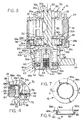
- a random orbital sander is designated as 10 and shown as generally including a manually manipulated housing 12 defining a downwardly opening chamber 14 sized to receive a motor 16 retained within the chamber by a lock or mounting ring 18 threadably fixed to the housing and including a balanced motor driven shaft 20; and a coupling 22 for mounting a sanding pad or disc 24 for orbital movement relating to the motor shaft.
- Motor 16 is shown in Figs. 1 - 3 as generally comprising a casing defined by upper and lower end or bearing support plates 26 and 28 having upwardly and downwardly facing recesses 26a and 28a for mounting uppermost and lowermost bearings 30 and 32 serving to support motor shaft 20 for rotation about a first axis 20a, and an annular side wall 36 cooperating with the end plates to bound a motor chamber 38 receiving a plurality of rotor blades 40 for rotation with the motor shaft.
- Recess 28a is radially bounded by a cylindrical side wall 28b having an outwardly facing cylindrical side wall surface 28c and an axially facing, annular end wall surface 28d.
- End plate 28 is also provided with an axially facing annular surface 28e extending outwardly of side wall surface 28c.
- Bearings 30 and 32 are formed, respectively, with inner and outer races 30a, 32a and 30b, 32b; and a plurality of ball or roller elements 30c, 32c.
- Chamber 38 is arranged for flow communication with a suitable source of fluid, such as air, under pressure via a valve controlled housing inlet passage 42 and a chamber inlet 44 and with a housing discharge passage 46 via a chamber discharge openings, not shown.
- Motor shaft 20 is suitably fixed for rotation with inner races 30a and 32a, and maintained in assembled condition relative to end plates 26 and 28 and side wall 36 by snap ring retainer 50.
- Motor shaft 20 is best shown in Figs. 3 and 5 as having an enlarged lower end 52, which includes a shaft balancing weight 54 and defines a downwardly opening cylindrical cavity or chamber 56.
- Cavity 56 is shown in Fig. 3 as being stepped to define an inner cylindrical recess surface 56a and a radially enlarged outer cylindrical recess surface 56b having an annular recess 58 for receiving a snap ring retainer 58a.
- Coupling 22 is best shown in Fig. 3 as including a bearing 60 formed with inner and outer races 60a and 60b, and ball or roller elements 60c, and a balancer bearing shaft 62, which is supported by inner bearing race 60a for rotation about a second axis 62a disposed parallel to motor shaft axis 20a.
- Bearing outer race 60b is sized to be slide fitted within cavity recess surface 56a and preferably retained therein by a suitable adhesive, such as Loctite.
- Balancer bearing shaft 62 is preferably press fit within the inner race 60a, and, if desired, bonded thereto by a suitable adhesive, such as Loctite.
- Sanding pad 24 may be suitably, removably fixed to balancer bearing shaft 62, such as by a fastener, not shown, threadably received within shaft opening 64 aligned with axis 62a.
- Balancer shaft 62 is shown as having an outwardly facing cylindrical surface 62b and axially facing annular surface 62c defined by an enlarged head portion 62d.
- sander is of known construction and generally disclosed, as by way of example, by commonly assigned U.S. Patents 4,854,085 and 5,538,086.
- an otherwise conventional orbital sander is provided with a first seal 70 intended to block ingress of dust particles into lowermost motor shaft support bearing 32, and a second seal 72 intended to prevent the ingress of dust particles into motor shaft mounted bearing 60.
- Seal 70 is shown in Figs. 3-9 as being of two part construction including a deformable washer 74 preferably formed of a 100% polyester felt material, and a cap 76 preferably formed of Nylon. Washer 74 is preferably air permeable, so as to allow the flow of pressurized air escaping from motor chamber 38 across bearing 32 for cooling purposes.
- Washer 74 is sized such that its outer diameter is sufficient to provide an annular, axially facing sealing surface 78 adapted to engage with end wall surface 28d of lower end plate 28 radially outwardly of bearing recess 28a and its inner diameter is such that there is provided a radially inwardly facing edge surface 82 disposed for rotary sliding engagement with a radially outwardly facing cylindrical surface 84 of the motor shaft.
- washer 74 In its as formed state, washer 74 has a flat rim portion with its oppositely facing annular sealing and clamping surfaces 78 and 86, respectively, essentially parallel to one another. In this construction, end wall surface 28d becomes a sealing surface and end plate annular surface 28e becomes a clamping surface.
- an axially facing surface 52a of motor shaft lower end 52 which extends radially of cylindrical surface 84, extends annularly of axis 20a through less than 360°, due to space limitations determined by the available distance between axis 20a and second axis 62a. However, if space allows, it is preferable to extend surface 52a through 360° in order to provide a further annular seal between surface 52a and washer clamping surface 86.
- Cap 76 is best shown in Figs. 3-7 and including radially extending annular flange portion 88, a cylindrical portion 90 arranged to depend from the radially inner edge of portion 88, and an annular flange portion 92 arranged to project radially inwardly from the lower edge of portion 90.
- Flange portion 88 has oppositely facing and essentially parallel first and second annular cap clamping surfaces 88a and 88b sized to extend radially outwardly of end plate side wall surface 28c for engagement with axially facing outer annular clamping surface 28e of end plate 28 and an o-ring 94 carried by lock ring 18.
- Cylindrical portion 90 has a radially inwardly facing surface 90a sized to be slidably supported by end plate side wall surface 28c.
- Cap flange portion 92 provides a third clamping surface 92a.
- o-ring 94 is adapted to be brought into clamping engagement with second cap clamping surface 88b for purposes of clamping first cap clamping surface 88a against end plate clamping surface 28e with the result that third cap clamping surface is drawn upwardly into clamping engagement with washer clamping surface 86 and washer scaling surface 78 forced into scaling engagement with end plate end wall surface 28d.
- the lower end 32b of outer race 32b projects slightly outwardly of recess 28a beyond end plate end wall surface 28d with the result that washer 74 is deformed, as shown in Figs.
- washer 74 serves to bridge between end plate 28 and motor shaft 20 and create a dust seal tending to prevent the ingress of dust particles to lower bearing 32.
- washer 74 also permits the reverse flow of air across bearing 32 each time motor 16 is turned off, but prevents passage of dust into the bearings which would otherwise occur in the absence of such washer.
- Second seal 72 is preferably in the form of a resiliently deformable ring fabricated of a high temperature, chemical and abrasion resistant material, such as 70 duro-carboxyladed nitrile material with balancer bearing shaft surfaces 62b and 62c serving to define cooperating sealing surfaces.
- the sealing ring is defined by a radially extending annular flange 96, a radially inwardly projecting flexible annular first sealing lip 98 and an axially projecting flexible annular second sealing lip 100.
- first seal lip 98 is resiliently deformed for rotary sealing engagement with balancer shaft surface 62b and second sealing lip is deformed for rotary sealing engagement with balancer shaft surface 62c incident to placement of the balancer shaft within bearing 60.
- flange 96 is such that installation of retainer 58a serves to clamp flange portion 96 in sealing engagement with a lower annular surface 60d of outer bearing race 60b and preferably also to resiliently deform the flange portion sufficiently to force its radially outwardly facing edge surface 102 into sealing engagement with recess surface 56b intermediate outer race 60b and retainer 58a.
- the sealing ring bridges between balancer bearing shaft 62 and motor shaft 20 and serves to create a dust seal tending to prevent ingress of dust particles into further bearing 60.
Landscapes
- Engineering & Computer Science (AREA)
- Mechanical Engineering (AREA)
- Finish Polishing, Edge Sharpening, And Grinding By Specific Grinding Devices (AREA)
- Grinding-Machine Dressing And Accessory Apparatuses (AREA)
Abstract
Description
- Random orbital sanders are well known and typically comprise a pneumatically operated motor having a casing suitably mounted within a manually manipulated housing and a balanced, motor shaft supported for rotation relative to the motor casing by uppermost and lowermost bearings; and a motor shaft mounted bearing serving to couple the motor shaft to a sanding pad or disc.
- Prior sanders of the type generally described are known to be subject to bearing failure resulting from the egress of dust particles thereinto during use. In this respect, a lowermost motor shaft support bearing is particularly subject to failure resulting from its direct exposure to a dusty or sanding environment during use and the tendency for dust ladened air to be momentarily drawn upwardly therethrough towards the interior of the motor each time the motor is turned off. The uppermost motor support bearing is known to have a substantially longer useful operating life in that it is normally shielded from dust, due to its placement wholly within the confines of the housing of the sander.
- There is no known means adopted for use in sealing the lowermost motor shaft supporting bearing against the ingress of dust particles, and thus resultant failure of such bearing can severely reduce the useful operating life of a random orbital sander, particularly when used in an environment where highly abrasive dust particles are generated.
- The motor shaft mounted bearing employed to couple the drive shaft to a sanding pad or disc is also know to be subject to failure due to the ingress of abrasive dust particles, and in commonly assigned U.S. Patent 4,854,085 there is described a dust seal having utility with this type of bearing. However, this dust seal has the disadvantage of being of multiple part construction.
- The present invention relates to seals particularly adapted to seal bearings of random orbital sanders against the egress of dust particles, such as would otherwise shorten the useful life of such sanders.
- There is disclosed two unique types of dust seals wherein a first of such seals is particularly adapted to create a seal against the ingress of dust into a lowermost bearing serving to mount a motor shaft for rotation relative to a motor casing, and a second of such seals is particularly adapted to create a seal against the ingress of dust into a motor shaft mounted bearing serving to couple the motor shaft to a sanding pad or disc to be driven thereby.
- In the first seal there is provided a deformable felt washer, which is adapted to bridge between and sealing engagement with the motor shaft and a lower end or bearing supporting plate of the motor casing, and a cap adapted to be clamped against the bearing supporting plate incident to mounting of the motor casing within the sander housing, whereupon the cap serves to clamp an outer peripheral surface of the washer in sealing engagement with the supporting plate. The washer has its central or through opening sized to provide a rotary sliding seal with a cylindrical, radially outwardly facing surface of the motor shaft and is preferably adapted to have an inner peripheral surface placed in sealing engagement with an axially facing, radially and annularly extending surface of the motor shaft incident to assembly of the motor shaft with the motor casing. The washer is preferably air permeable to allow flow of pressurized air escaping from the motor across the lowermost bearing for cooling purposes.
- In the second seal, there is provided a resiliently deformable sealing ring having a radially outwardly facing peripheral edge surface adapted to be positioned in sealing engagement with a radially inwardly facing surface of the motor shaft; an adjacently dispersed axially facing surface adopted to be positioned in sealing engagement with an outer race of the motor shaft supported bearing; a first resiliently deformable annular lip arranged to project radially inwardly of the sealing ring for rotary sliding engagement with a radially outwardly facing cylindrical surface of a balancer bearing shaft forming part of the coupling for the sanding pad or disc, and a second resiliently deformable, annular lip arranged to project axially of the sealing ring for rotary sliding engagement with an axially facing, radially extending surface of the balancer bearing shaft.
- Fig.1
- is a prospective view of a manually manipulated, pneumatically operated sander incorporating the present invention with portions of its housing broken away;
- Fig. 2
- is an enlarged side elevational view of the motor and balancer assemblies with the assembly mounting or lock ring removed;
- Fig. 3
- is an enlarged sectional view taken generally along the line 3-3 in Fig. 2 with the mounting ring shown in unclamping position;
- Fig. 4
- is fragmentary view showing the mounting ring in clamping position;
- Fig. 5
- is an exploded, prospective view showing elements of the balancer assembly;
- Fig. 6
- is a view of the upper bearing seal dust cap shown in section;
- Fig. 7
- is a top plan view of the upper bearing seal dust cap;
- Fig. 8
- is a top plan view of the upper bearing seal washer;
- Fig. 9
- is a side elevational view of the upper bearing seal washer;
- Fig. 10
- is an enlarged view of the lower bearing flexible ring seal shown in section; and
- Fig. 11
- is a top plan view of the lower bearing ring seal.
- Reference is first made to Fig. 1, wherein a random orbital sander is designated as 10 and shown as generally including a manually manipulated
housing 12 defining a downwardlyopening chamber 14 sized to receive amotor 16 retained within the chamber by a lock or mountingring 18 threadably fixed to the housing and including a balanced motor drivenshaft 20; and acoupling 22 for mounting a sanding pad ordisc 24 for orbital movement relating to the motor shaft. -
Motor 16 is shown in Figs. 1 - 3 as generally comprising a casing defined by upper and lower end orbearing support plates recesses lowermost bearings motor shaft 20 for rotation about afirst axis 20a, and anannular side wall 36 cooperating with the end plates to bound amotor chamber 38 receiving a plurality ofrotor blades 40 for rotation with the motor shaft.Recess 28a is radially bounded by a cylindrical side wall 28b having an outwardly facing cylindricalside wall surface 28c and an axially facing, annularend wall surface 28d.End plate 28 is also provided with an axially facingannular surface 28e extending outwardly ofside wall surface 28c. -
Bearings outer races roller elements Chamber 38 is arranged for flow communication with a suitable source of fluid, such as air, under pressure via a valve controlledhousing inlet passage 42 and achamber inlet 44 and with ahousing discharge passage 46 via a chamber discharge openings, not shown. -
Motor shaft 20 is suitably fixed for rotation withinner races end plates side wall 36 bysnap ring retainer 50. -
Motor shaft 20 is best shown in Figs. 3 and 5 as having an enlargedlower end 52, which includes ashaft balancing weight 54 and defines a downwardly opening cylindrical cavity orchamber 56.Cavity 56 is shown in Fig. 3 as being stepped to define an inner cylindrical recess surface 56a and a radially enlarged outercylindrical recess surface 56b having anannular recess 58 for receiving asnap ring retainer 58a. -
Coupling 22 is best shown in Fig. 3 as including abearing 60 formed with inner andouter races 60a and 60b, and ball orroller elements 60c, and abalancer bearing shaft 62, which is supported by inner bearing race 60a for rotation about asecond axis 62a disposed parallel tomotor shaft axis 20a. - Bearing
outer race 60b is sized to be slide fitted within cavity recess surface 56a and preferably retained therein by a suitable adhesive, such as Loctite.Balancer bearing shaft 62 is preferably press fit within the inner race 60a, and, if desired, bonded thereto by a suitable adhesive, such as Loctite.Sanding pad 24 may be suitably, removably fixed to balancer bearingshaft 62, such as by a fastener, not shown, threadably received within shaft opening 64 aligned withaxis 62a. -
Balancer shaft 62 is shown as having an outwardly facingcylindrical surface 62b and axially facingannular surface 62c defined by an enlargedhead portion 62d. - As thus far described, sander is of known construction and generally disclosed, as by way of example, by commonly assigned U.S. Patents 4,854,085 and 5,538,086.
- In accordance with the present invention, an otherwise conventional orbital sander is provided with a
first seal 70 intended to block ingress of dust particles into lowermost motor shaft support bearing 32, and asecond seal 72 intended to prevent the ingress of dust particles into motor shaft mountedbearing 60. -
Seal 70 is shown in Figs. 3-9 as being of two part construction including adeformable washer 74 preferably formed of a 100% polyester felt material, and acap 76 preferably formed of Nylon. Washer 74 is preferably air permeable, so as to allow the flow of pressurized air escaping frommotor chamber 38 across bearing 32 for cooling purposes. -
Washer 74 is sized such that its outer diameter is sufficient to provide an annular, axially facingsealing surface 78 adapted to engage withend wall surface 28d oflower end plate 28 radially outwardly ofbearing recess 28a and its inner diameter is such that there is provided a radially inwardly facingedge surface 82 disposed for rotary sliding engagement with a radially outwardly facingcylindrical surface 84 of the motor shaft. In its as formed state,washer 74 has a flat rim portion with its oppositely facing annular sealing andclamping surfaces end wall surface 28d becomes a sealing surface and end plateannular surface 28e becomes a clamping surface. - In the illustrated construction, an axially facing surface 52a of motor shaft
lower end 52, which extends radially ofcylindrical surface 84, extends annularly ofaxis 20a through less than 360°, due to space limitations determined by the available distance betweenaxis 20a andsecond axis 62a. However, if space allows, it is preferable to extend surface 52a through 360° in order to provide a further annular seal between surface 52a andwasher clamping surface 86. -
Cap 76 is best shown in Figs. 3-7 and including radially extendingannular flange portion 88, acylindrical portion 90 arranged to depend from the radially inner edge ofportion 88, and anannular flange portion 92 arranged to project radially inwardly from the lower edge ofportion 90.Flange portion 88 has oppositely facing and essentially parallel first and second annularcap clamping surfaces side wall surface 28c for engagement with axially facing outerannular clamping surface 28e ofend plate 28 and an o-ring 94 carried bylock ring 18.Cylindrical portion 90 has a radially inwardly facingsurface 90a sized to be slidably supported by end plateside wall surface 28c.Cap flange portion 92 provides a third clamping surface 92a. - It will be understood by referring to Figs. 1 and 3 that upon threadably connecting
lock ring 18 tohousing 12 for purposes of mounting motor, o-ring 94 is adapted to be brought into clamping engagement with secondcap clamping surface 88b for purposes of clamping firstcap clamping surface 88a against endplate clamping surface 28e with the result that third cap clamping surface is drawn upwardly into clamping engagement withwasher clamping surface 86 andwasher scaling surface 78 forced into scaling engagement with end plateend wall surface 28d. In the arrangement shown in the drawings thelower end 32b ofouter race 32b projects slightly outwardly ofrecess 28a beyond end plateend wall surface 28d with the result thatwasher 74 is deformed, as shown in Figs. 3 and 4, aslock ring 18 is threaded intohousing 12, andsurface 78 is also placed in tight sealing engagement with outer bearinglower end 32b. With this construction,washer 74 serves to bridge betweenend plate 28 andmotor shaft 20 and create a dust seal tending to prevent the ingress of dust particles to lowerbearing 32. - During operation of
sander 10, pressurized air tends to escape frommotor chamber 38 through the annular path defined bylower end plate 28 andmotor shaft 20, and due to the air permeable nature ofwasher 74, is permitted to flow axially of bearing 32 in order to cool such bearing.Washer 74, also permits the reverse flow of air across bearing 32 eachtime motor 16 is turned off, but prevents passage of dust into the bearings which would otherwise occur in the absence of such washer. -
Second seal 72 is preferably in the form of a resiliently deformable ring fabricated of a high temperature, chemical and abrasion resistant material, such as 70 duro-carboxyladed nitrile material with balancer bearing shaft surfaces 62b and 62c serving to define cooperating sealing surfaces. - The sealing ring is defined by a radially extending
annular flange 96, a radially inwardly projecting flexible annular first sealinglip 98 and an axially projecting flexible annularsecond sealing lip 100. As best shown in Fig. 3 the elements of the sealing ring are sized such thatfirst seal lip 98 is resiliently deformed for rotary sealing engagement withbalancer shaft surface 62b and second sealing lip is deformed for rotary sealing engagement withbalancer shaft surface 62c incident to placement of the balancer shaft within bearing 60. Also, it will be understood that the thickness and diameter offlange 96 is such that installation ofretainer 58a serves to clampflange portion 96 in sealing engagement with a lowerannular surface 60d ofouter bearing race 60b and preferably also to resiliently deform the flange portion sufficiently to force its radially outwardly facingedge surface 102 into sealing engagement withrecess surface 56b intermediateouter race 60b andretainer 58a. - With this construction, the sealing ring bridges between
balancer bearing shaft 62 andmotor shaft 20 and serves to create a dust seal tending to prevent ingress of dust particles intofurther bearing 60.
Claims (7)
- A random orbital sander comprising:a manually manipulated housing having a downward opening chamber and pressurized fluid inlet and fluid outlets communicating with said chamber;a pressurized fluid operated motor including a motor casing arranged within said chamber and a counter balanced motor shaft depending from said casing and supported for driven rotation about a first axis by upper and lower casing mounted bearings incident to the introduction of pressurized fluid into said casing from said chamber;a first sealing means bridging between said motor shaft and said casing for providing a dust seal for said lower bearing;coupling means for drivingly connecting a sanding pad to said motor shaft for rotation about a second axis disposed parallel to said first axis, said coupling means including a further bearing and a balancer bearing shaft supported by said further bearing for rotation about said second axis; anda second sealing means bridging between said balancer bearing shaft and said motor shaft for providing a dust seal for said further bearing.
- A sander according to claim 1, wherein said casing includes an end plate having an annular, axially facing clamping surface and a cylindrical wall portion bounding a recess for receiving said lower bearing, said wall portion having an annular axially facing end wall sealing surface; said motor shaft has a radially outwardly facing cylindrical sealing surface; and said first sealing means includes a deformable sealing washer having a radially inwardly facing annular edge surface arranged for rotary sealing engagement with said cylindrical sealing surface of said motor shaft and an outer annular rim portion having axially oppositely facing annular washer sealing and clamping surfaces, and a cap for clamping said washer sealing surface against said end wall sealing surface of said end plate, said cap having a radially outwardly facing annular flange having axially oppositely facing first and second cap clamping surfaces and a radially inwardly facing annular flange having an axially facing third annular cap clamping surface, and clamping means engaging with said second cap clamping surface for clamping said first cap clamping surface against said clamping surface of said end plate and placing said third cap clamping surface in clamping engagement with said washer clamping surface and said washer sealing surface in sealing engagement with said end wall sealing surface of said end plate.
- A sander according to claim 2, wherein said clamping means additionally serves to retain said motor casing within said chamber.
- A sander according to claim 2, wherein said lower bearing includes inner and outer races fixed to said casing and motor shaft, respectively, and said outer race has a portion thereof projecting outwardly from said recess of said end plate beyond said end wall sealing surface, and said washer sealing surface sealingly engages with said portion of said outer race.
- A sander according to claim 4, wherein said clamping means additionally serves to retain said motor casing within said chamber.
- A sander according to claim 2, wherein said motor shaft defines a downwardly opening recess for receiving said further bearing and being bounded by a retaining means receiving recess, said bearing receiving recess of said motor shaft defining a radially inwardly facing cylindrical sealing surface disposed axially inwardly of said retaining means receiving recess, said further bearing including an outer race and an inner race, said outer race of said further bearing being fixed within said bearing receiving recess of said motor shaft and defining an axially facing clamping surface, said balancer bearing shaft being fixed to said inner race of said further bearing and having a radially outwardly facing cylindrical sealing surface and an axially facing annular sealing surface, and said sealing means includes a resiliently deformable sealing ring, said ring having a radially extending annular flange portion, a radially inwardly projecting annular first sealing lip joined to said flange portion and an axially projecting annular second sealing lip joined to said flange portion, and a retaining means insertable in to said retaining means receiving recess and cooperating with said clamping surface of said outer race of said further bearing to resiliently deformably clamp said flange portion of said sealing ring therebetween, and retain said first and second sealing lips in resiliently deformable engagement with said cylindrical sealing surface and axially facing sealing surface of said balancer bearing shaft respectively.
- A sander according to claim 6, wherein said recess of said motor shaft defines an inwardly facing cylindrical surface arranged axially intermediate said retaining means receiving recess and said clamping surface of said outer race of said further bearing and said flange of said sealing ring has a radially outwardly facing edge surface sized to expand into sealingly engagement with said cylindrical surface of said recess incident to clamping of said flange portion of said ring between said clamping surface of said outer race of said further bearing and said retaining means.
Applications Claiming Priority (2)
| Application Number | Priority Date | Filing Date | Title |
|---|---|---|---|
| US305486 | 1994-09-13 | ||
| US10/305,486 US6878049B2 (en) | 2002-11-26 | 2002-11-26 | Random orbital sander |
Publications (2)
| Publication Number | Publication Date |
|---|---|
| EP1424164A1 true EP1424164A1 (en) | 2004-06-02 |
| EP1424164B1 EP1424164B1 (en) | 2011-07-06 |
Family
ID=32298054
Family Applications (1)
| Application Number | Title | Priority Date | Filing Date |
|---|---|---|---|
| EP03025559A Expired - Lifetime EP1424164B1 (en) | 2002-11-26 | 2003-11-08 | Random orbital sander |
Country Status (3)
| Country | Link |
|---|---|
| US (1) | US6878049B2 (en) |
| EP (1) | EP1424164B1 (en) |
| CN (1) | CN100519074C (en) |
Cited By (1)
| Publication number | Priority date | Publication date | Assignee | Title |
|---|---|---|---|---|
| EP4241922A1 (en) * | 2022-03-10 | 2023-09-13 | X'Pole Precision Tools Inc. | Dustproof structure of grinding tool holder |
Families Citing this family (21)
| Publication number | Priority date | Publication date | Assignee | Title |
|---|---|---|---|---|
| US7198559B2 (en) * | 2004-12-23 | 2007-04-03 | Black & Decker, Inc. | Modular sander-casing architecture |
| US7846011B2 (en) * | 2005-03-24 | 2010-12-07 | Black & Decker Inc. | Belt sander |
| US7226348B1 (en) * | 2005-10-07 | 2007-06-05 | Tse-Hua Chang | Air sander grinder |
| US8435073B2 (en) | 2010-10-08 | 2013-05-07 | John Mezzalingua Associates, LLC | Connector assembly for corrugated coaxial cable |
| US9172156B2 (en) | 2010-10-08 | 2015-10-27 | John Mezzalingua Associates, LLC | Connector assembly having deformable surface |
| US8449325B2 (en) * | 2010-10-08 | 2013-05-28 | John Mezzalingua Associates, LLC | Connector assembly for corrugated coaxial cable |
| US8439703B2 (en) | 2010-10-08 | 2013-05-14 | John Mezzalingua Associates, LLC | Connector assembly for corrugated coaxial cable |
| US8430688B2 (en) | 2010-10-08 | 2013-04-30 | John Mezzalingua Associates, LLC | Connector assembly having deformable clamping surface |
| US8458898B2 (en) | 2010-10-28 | 2013-06-11 | John Mezzalingua Associates, LLC | Method of preparing a terminal end of a corrugated coaxial cable for termination |
| US8628352B2 (en) | 2011-07-07 | 2014-01-14 | John Mezzalingua Associates, LLC | Coaxial cable connector assembly |
| CN102335848B (en) * | 2011-08-14 | 2014-07-23 | 张紫娟 | Pneumatic wall surface grinding machine with handle |
| US9083113B2 (en) | 2012-01-11 | 2015-07-14 | John Mezzalingua Associates, LLC | Compression connector for clamping/seizing a coaxial cable and an outer conductor |
| US9099825B2 (en) | 2012-01-12 | 2015-08-04 | John Mezzalingua Associates, LLC | Center conductor engagement mechanism |
| US9017102B2 (en) | 2012-02-06 | 2015-04-28 | John Mezzalingua Associates, LLC | Port assembly connector for engaging a coaxial cable and an outer conductor |
| EP3132892B1 (en) * | 2015-08-20 | 2020-11-18 | Techtronic Power Tools Technology Limited | Multi-sander kit |
| TWI584910B (en) * | 2015-12-02 | 2017-06-01 | X'pole Prec Tools Inc | Machine tool dust blocking structure |
| US11964352B2 (en) * | 2018-02-14 | 2024-04-23 | Robert Bosch Tool Corporation | Multi-motion accessory |
| EP3656503B1 (en) * | 2018-10-29 | 2023-10-18 | Guido Valentini | Hand-held and hand-guided random orbital polishing or sanding power tool |
| EP3693132B1 (en) | 2019-02-08 | 2023-09-06 | Guido Valentini | Hand-held and hand-guided random orbital polishing or sanding power tool |
| CN116728241A (en) * | 2022-03-04 | 2023-09-12 | 鼎朋企业股份有限公司 | Dust-proof structure of grinding tool holder |
| US20230286103A1 (en) * | 2022-03-11 | 2023-09-14 | X'pole Precision Tools Inc. | Dustproof structure of grinding tool holder |
Citations (2)
| Publication number | Priority date | Publication date | Assignee | Title |
|---|---|---|---|---|
| US5445558A (en) * | 1994-07-20 | 1995-08-29 | Hutchins Manufacturing Company | Wet sander |
| US5879228A (en) | 1997-11-14 | 1999-03-09 | Sun; Yung-Yung | Pneumatic grinding/polishing machine |
Family Cites Families (7)
| Publication number | Priority date | Publication date | Assignee | Title |
|---|---|---|---|---|
| US4854085A (en) | 1987-09-24 | 1989-08-08 | Dynabrade, Inc. | Random orbital sander |
| US5538086A (en) | 1994-12-27 | 1996-07-23 | Wright; Rocky A. | Variable orientation attachment implement |
| US6257970B1 (en) * | 1997-01-23 | 2001-07-10 | Hao Chien Chao | Ergonomically friendly random orbital construction |
| US6004197A (en) * | 1997-01-23 | 1999-12-21 | Hao Chien Chao | Ergonomically friendly random orbital sander construction |
| US5823862A (en) * | 1997-02-21 | 1998-10-20 | Dynabrade, Inc. | Dual action sander |
| DE19711552C1 (en) * | 1997-03-20 | 1998-09-24 | Gansow Maschbau Gmbh Co Kg | Motor-driven rotating plate with cleaning tools for a floor cleaning machine |
| US6343982B1 (en) * | 2000-08-15 | 2002-02-05 | Yung Yung Sun | Pneumatic sander structure |
-
2002
- 2002-11-26 US US10/305,486 patent/US6878049B2/en not_active Expired - Lifetime
-
2003
- 2003-11-08 EP EP03025559A patent/EP1424164B1/en not_active Expired - Lifetime
- 2003-11-26 CN CNB2003101179843A patent/CN100519074C/en not_active Expired - Lifetime
Patent Citations (2)
| Publication number | Priority date | Publication date | Assignee | Title |
|---|---|---|---|---|
| US5445558A (en) * | 1994-07-20 | 1995-08-29 | Hutchins Manufacturing Company | Wet sander |
| US5879228A (en) | 1997-11-14 | 1999-03-09 | Sun; Yung-Yung | Pneumatic grinding/polishing machine |
Cited By (1)
| Publication number | Priority date | Publication date | Assignee | Title |
|---|---|---|---|---|
| EP4241922A1 (en) * | 2022-03-10 | 2023-09-13 | X'Pole Precision Tools Inc. | Dustproof structure of grinding tool holder |
Also Published As
| Publication number | Publication date |
|---|---|
| CN100519074C (en) | 2009-07-29 |
| US20040102145A1 (en) | 2004-05-27 |
| US6878049B2 (en) | 2005-04-12 |
| EP1424164B1 (en) | 2011-07-06 |
| CN1502444A (en) | 2004-06-09 |
Similar Documents
| Publication | Publication Date | Title |
|---|---|---|
| EP1424164B1 (en) | Random orbital sander | |
| US4059205A (en) | Rotary valve | |
| CA1235950A (en) | Slurry pump mechanical seal mounting assembly | |
| US7077734B2 (en) | Eccentric grinding hand power tool | |
| US4427204A (en) | Mechanical end face seal | |
| US4986036A (en) | Abrading or polishing tool | |
| US5368311A (en) | Shaft seal assembly for a rotary valve | |
| US20040119280A1 (en) | Fluid coolant union | |
| US6789804B2 (en) | Dry gas shutdown seal | |
| WO2000046530A1 (en) | Improved bearing isolator | |
| JPH01197225A (en) | Bucket wheel gate | |
| US5071139A (en) | Pressure activated emergency/temporary seal | |
| CA1335112C (en) | Mechanical seal for pumps | |
| EP0211051B1 (en) | Mechanical seal | |
| CA1325648C (en) | Mechanical seal for pumps and method of fabricating same | |
| CA2406103C (en) | Dust seal | |
| US4281839A (en) | Rotary face sealing apparatus | |
| US6592345B2 (en) | Scroll compressor | |
| US7108418B2 (en) | Bearing seal assembly for concrete auger mixer and method for using same | |
| JP2000161373A (en) | Seal structure of pneumatic rotating device | |
| JPS6256390B2 (en) | ||
| CN1077833C (en) | Motor-driven hand unit | |
| US3598417A (en) | Nonfriction seal | |
| JP7235626B2 (en) | mechanical seal | |
| JPS6326465A (en) | Machine-surface sealing device |
Legal Events
| Date | Code | Title | Description |
|---|---|---|---|
| PUAI | Public reference made under article 153(3) epc to a published international application that has entered the european phase |
Free format text: ORIGINAL CODE: 0009012 |
|
| AK | Designated contracting states |
Kind code of ref document: A1 Designated state(s): AT BE BG CH CY CZ DE DK EE ES FI FR GB GR HU IE IT LI LU MC NL PT RO SE SI SK TR |
|
| AX | Request for extension of the european patent |
Extension state: AL LT LV MK |
|
| 17P | Request for examination filed |
Effective date: 20041125 |
|
| AKX | Designation fees paid |
Designated state(s): DE GB |
|
| 17Q | First examination report despatched |
Effective date: 20090206 |
|
| GRAP | Despatch of communication of intention to grant a patent |
Free format text: ORIGINAL CODE: EPIDOSNIGR1 |
|
| GRAS | Grant fee paid |
Free format text: ORIGINAL CODE: EPIDOSNIGR3 |
|
| GRAA | (expected) grant |
Free format text: ORIGINAL CODE: 0009210 |
|
| AK | Designated contracting states |
Kind code of ref document: B1 Designated state(s): DE GB |
|
| REG | Reference to a national code |
Ref country code: GB Ref legal event code: FG4D |
|
| REG | Reference to a national code |
Ref country code: DE Ref legal event code: R096 Ref document number: 60337608 Country of ref document: DE Effective date: 20110908 |
|
| PLBE | No opposition filed within time limit |
Free format text: ORIGINAL CODE: 0009261 |
|
| STAA | Information on the status of an ep patent application or granted ep patent |
Free format text: STATUS: NO OPPOSITION FILED WITHIN TIME LIMIT |
|
| 26N | No opposition filed |
Effective date: 20120411 |
|
| REG | Reference to a national code |
Ref country code: DE Ref legal event code: R097 Ref document number: 60337608 Country of ref document: DE Effective date: 20120411 |
|
| PGFP | Annual fee paid to national office [announced via postgrant information from national office to epo] |
Ref country code: GB Payment date: 20221010 Year of fee payment: 20 Ref country code: DE Payment date: 20221109 Year of fee payment: 20 |
|
| REG | Reference to a national code |
Ref country code: DE Ref legal event code: R071 Ref document number: 60337608 Country of ref document: DE |
|
| REG | Reference to a national code |
Ref country code: GB Ref legal event code: PE20 Expiry date: 20231107 |
|
| PG25 | Lapsed in a contracting state [announced via postgrant information from national office to epo] |
Ref country code: GB Free format text: LAPSE BECAUSE OF EXPIRATION OF PROTECTION Effective date: 20231107 |
|
| PG25 | Lapsed in a contracting state [announced via postgrant information from national office to epo] |
Ref country code: GB Free format text: LAPSE BECAUSE OF EXPIRATION OF PROTECTION Effective date: 20231107 |