EP1424160B1 - Cutting machine - Google Patents
Cutting machine Download PDFInfo
- Publication number
- EP1424160B1 EP1424160B1 EP03009781.0A EP03009781A EP1424160B1 EP 1424160 B1 EP1424160 B1 EP 1424160B1 EP 03009781 A EP03009781 A EP 03009781A EP 1424160 B1 EP1424160 B1 EP 1424160B1
- Authority
- EP
- European Patent Office
- Prior art keywords
- frame
- profiled element
- machine
- receiving
- face
- Prior art date
- Legal status (The legal status is an assumption and is not a legal conclusion. Google has not performed a legal analysis and makes no representation as to the accuracy of the status listed.)
- Expired - Lifetime
Links
Images




Classifications
-
- B—PERFORMING OPERATIONS; TRANSPORTING
- B28—WORKING CEMENT, CLAY, OR STONE
- B28D—WORKING STONE OR STONE-LIKE MATERIALS
- B28D1/00—Working stone or stone-like materials, e.g. brick, concrete or glass, not provided for elsewhere; Machines, devices, tools therefor
- B28D1/02—Working stone or stone-like materials, e.g. brick, concrete or glass, not provided for elsewhere; Machines, devices, tools therefor by sawing
- B28D1/04—Working stone or stone-like materials, e.g. brick, concrete or glass, not provided for elsewhere; Machines, devices, tools therefor by sawing with circular or cylindrical saw-blades or saw-discs
- B28D1/047—Working stone or stone-like materials, e.g. brick, concrete or glass, not provided for elsewhere; Machines, devices, tools therefor by sawing with circular or cylindrical saw-blades or saw-discs with the work mounted on a carriage
-
- B—PERFORMING OPERATIONS; TRANSPORTING
- B23—MACHINE TOOLS; METAL-WORKING NOT OTHERWISE PROVIDED FOR
- B23D—PLANING; SLOTTING; SHEARING; BROACHING; SAWING; FILING; SCRAPING; LIKE OPERATIONS FOR WORKING METAL BY REMOVING MATERIAL, NOT OTHERWISE PROVIDED FOR
- B23D47/00—Sawing machines or sawing devices working with circular saw blades, characterised only by constructional features of particular parts
- B23D47/02—Sawing machines or sawing devices working with circular saw blades, characterised only by constructional features of particular parts of frames; of guiding arrangements for work-table or saw-carrier
- B23D47/025—Sawing machines or sawing devices working with circular saw blades, characterised only by constructional features of particular parts of frames; of guiding arrangements for work-table or saw-carrier of tables
-
- B—PERFORMING OPERATIONS; TRANSPORTING
- B23—MACHINE TOOLS; METAL-WORKING NOT OTHERWISE PROVIDED FOR
- B23D—PLANING; SLOTTING; SHEARING; BROACHING; SAWING; FILING; SCRAPING; LIKE OPERATIONS FOR WORKING METAL BY REMOVING MATERIAL, NOT OTHERWISE PROVIDED FOR
- B23D47/00—Sawing machines or sawing devices working with circular saw blades, characterised only by constructional features of particular parts
- B23D47/04—Sawing machines or sawing devices working with circular saw blades, characterised only by constructional features of particular parts of devices for feeding, positioning, clamping, or rotating work
- B23D47/045—Sawing machines or sawing devices working with circular saw blades, characterised only by constructional features of particular parts of devices for feeding, positioning, clamping, or rotating work feeding work into engagement with the saw blade
Definitions
- This invention concerns a cutting machine for building, in particular a work-site machine suitable for cutting tiles, stones, stone material, bricks and the like.
- the carriage comprises a metal plate to which a plurality of wheels is fixed by welding, which wheels are suitable for being slidably coupled with said guides to enable the movement of the product.
- Dispensers of a jet of water are associated with the blade, which cools the cutting edge of the blade and keeps it clean.
- a tank for collecting the cooling and washing water and the waste generated by the cutting operations is furthermore fixed to the frame of the machine in such a manner as to be underneath the carriage and the blade.
- DE20107761U discloses frame means for a cutting machine comprising rim means, carriage means and cutting means, wherein the rim means comprises profiled elements that are internally provided with rib means which subdivides said profiled element means into a plurality of chamber means suitable for receiving connecting means arranged for connecting a plurality of portions of said profiled element means to obtain said frame means.
- DE1193888 discloses frame means for a cutting machine comprising rim means, carriage means and cutting means, wherein the rim means comprises profiled elements.
- a drawback of the machines mentioned above consists in the fact that they are provided with a frame obtained from a metal structure, said frame being in fact usually produced with metal material, such as metal sheet, which is appropriately cut, bent and welded.
- Said frame has therefore to be fabricated separately and subsequently be associated with the further components that form the machine.
- Said frame comprises a workbench, to which the carriage guides and the blade have to be fixed, and a plurality of supporting feet that provide the machine with the necessary stability during operation.
- said frames are usually painted, they may become scratched or damaged during handling.
- the structure of said machines is in fact such that it makes it rather difficult to rationally use the loading compartments of the means of transport, for example a container or the body of a truck.
- two or more machines cannot be associated with one another in such a way that a portion of one of them is received in the zone of a further machine defined by the bottom part of the workbench, by the tank associated with the workbench and by the supporting feet.
- a further drawback is that, since the frames are obtained from a metal structure, they have very high dimensional tolerances which causes that finished machines of the same type have dimensions significantly different from one another.
- An object of the invention is to improve the prior art cutting machines for building.
- Another object of the invention is to obtain a cutting machine for building that is particularly light and easy to be transported.
- a further object of the invention is to obtain a machine provided with a frame that does not need to be made separately and stored until subsequent assembly operations.
- a still further object of the invention is to obtain a machine that takes up an appreciably reduced amount of space during the transport phase.
- a further object of the invention is to obtain a cutting machine that can be stacked onto further machines of the same type.
- frame means are provided suitable for being associated with a cutting machine for building, comprising rim means to which carriage means suitable for receiving a product to be cut and cutting means suitable for cutting said product are associatable, said rim means comprising profiled element means that is internally provided with rib means which subdivides said profiled element means into a plurality of chamber means, said frame means further comprising connecting means connecting a plurality of portions of said profiled element means to obtain said frame means, said connecting means being provided with appendices, said plurality of chamber means receiving said appendices, said frame means further comprising supporting foot means, said connecting means further comprising compartment means receiving said supporting foot means of said frame means slidable inside said compartment means.
- the profiled element means comprises an aluminium profiled element obtained by extrusion.
- the profiled element means comprises groove means made on a face of said profiled element means and suitable for receiving fixing means for fixing the sliding means to the profiled element means.
- the groove means extends longitudinally along the entire length of the profiled element means so as to allow the sliding means to be fixed to any section of the profiled element means.
- the profiled element means further comprises cavity means obtained on a further face of the profiled element means, said further face being opposite to said face, said cavity means being suitable for receiving a sharpened end of a cutting blade of the machine.
- the products supported by the profiled element means can be separated in such a way as to create parts with preset dimensions, by subjecting said products to a through cut carried out by the blade.
- the profiled element means comprises further cavity means obtained on said further face and contained in a plane tilted by about 45° with respect to the plane containing said cavity means.
- Said further cavity means is suitable for receiving said end of the blade to enable tilted cuts to be made in the products.
- Figures 1 to 9 show a cutting machine for building 1 that is particularly suitable for cutting building products such as tiles, stones, stone material, bricks and the like.
- the machine 1 comprises a frame 2 to which cutting means 3 can be fixed that are provided with a blade 6 suitable for cutting said products.
- the machine 1 further comprises a carriage 4 slidable on guides 5 that are connected to the frame 2, said carriage 4 being suitable for supporting said building products to move them towards or away from the blade 6.
- the cutting means 3 may be placed in a first work position in which the blade 6 is arranged substantially perpendicularly to the plane identified by the carriage 4, and in a second work position in which the blade 6 forms an angle of approximately 45° with respect to the plane defined by the carriage 4.
- the machine 1 further comprises a tank 24 associated to the bottom of the frame 2 and suitable for collecting the water used during cutting operations for cooling and keeping clean the blade 6.
- the carriage 4 comprises a supporting element 7 for supporting a building product to be cut, with which sliding means 8 is associated provided with wheels 9 suitable for engaging with the guides 5.
- the carriage 4 further comprises, at one end thereof, a plate 10 that acts as supporting stop for the building products and with which a ruler 11 is associated, said ruler 11 acting as reference for a cutting operator.
- the carriage 4 further comprises, at a further end thereof opposite to said end, closing means 56 arranged for preventing water and/or dirt from penetrating inside the supporting element 7.
- the carriage 4 further comprises a protractor 12 that enables said products to be cut according to inclined planes.
- the supporting element 7 is made from a profiled element 13 that is advantageously obtained in aluminium by extrusion.
- the profiled element 13 comprises a pair of longitudinal grooves 14, 15 extending along the entire length of the profiled element 13 and suitable for receiving fixing means 74 of the sliding means 8.
- the grooves 14, 15 are obtained in opposite end regions 16, 17 of a face 13a of the profiled element 13.
- the profiled element 13 further comprises protrusions 20, 21 that project from the face 13a, each of said protrusions 20, 21 being obtained near one of the grooves 14, 15 to constitute a shoulder that enables the sliding means to be correctly positioned 8 and. to prevent said sliding means 8 from shifting once it has been fixed to the profiled element 13.
- the profiled element 13 further comprises a cavity 18 obtained on a further face 13b, opposite to the face 13a, substantially in the middle of the profiled element 13.
- the cavity 18 is shaped in such a way as to receive a sharpened end of the blade 6, when the latter is in the first operating position described above.
- the profiled element 13 is further provided with a further cavity 19 obtained on the further face 13b that is substantially tilted by 45° with respect to the plane identified by the profiled element 13.
- the further cavity 19 is therefore suitable for receiving the sharpened end of the blade when the latter is in the second operating position described above.
- the cavity 18 and the further cavity 19 are shaped in such a way as to as to extend along the entire length of the profiled element 13.
- the profiled element 13 further comprises, on the further face 13b, in the opposite end regions 16, 17, further grooves 22, 23, which further grooves 22, 23 also extend along the entire length of the profiled element 13.
- the further grooves 22, 23 are arranged for collecting the cooling and washing water and directing it inside the tank 24.
- the profiled element 13 is internally provided with ribs 26 that define a plurality of seats 27 arranged for receiving screws suitable for fixing the plate 10 to the profiled element 13.
- the profiled element 13 further comprises a further rib 28 positioned at the cavity 18 and which partially protrudes from the face 13a.
- the further rib 28 constitutes a supporting element cooperating with the protrusions 20, 21 to reduce the risk of hot deformation of the profiled element 13, when the latter is ejected from the extrusion unit.
- the frame 2 consists of a first part 29, a second part 30, a third part 31 and a fourth part 32 of a further profiled element 33.
- the further profiled element 33 is made of extruded aluminium.
- the first part 29, the second part 30, the third part 31 and the fourth part 32 are connected together to form a rim 36 that has a substantially rectangular shape, at the top of which there is connecting means 34 provided with fixing screws 35.
- the further profiled element 33 comprises a rib 37 and a further rib 38 that define inside said further profiled element 33 a first chamber 45, a second chamber 46 and a third chamber 47 arranged for receiving appendices 39 ( Figure 6 ) of the connecting means 34, as will be described in detail below.
- the rib 37 and the further rib 38 define a respective seat 40, 41 suitable for receiving a fixing screw 35.
- the further profiled element 33 further comprises a groove 42 extending longitudinally therein, said groove 42 opening onto a face 33a of the further profiled element 33 and being suitable for receiving fixing means 43 suitable for fixing the guides 5.
- the fixing means 43 comprises screws 44 the head of which are suitable for being laterally inserted inside the groove 42 and for being shapingly received in said groove 42.
- the fixing means 43 before the screws 44 are tightened, can be moved along the groove 42 in such a way as to adjust the distance that separates the guide 5.
- the use of the further profiled element 33 according to the invention therefore enables frames to be made that can be associated with carriages of dimensions belonging to a wide range of sizes, by simply adjusting the reciprocal distance between the guides 5 in such a way that they can be slidably coupled to the wheels of said carriages.
- the blade 6 is received during cutting operations inside the cavity 18, or inside the further cavity 19.
- the groove 42 is further suitable for receiving connecting means of a band, which is not shown, that promotes the conveying of the cooling and washing water inside the tank 24.
- said band is made from partially flexible plastic material and has a bottom strip that can be superimposed on a side wall of the tank 24 to promote drainage of the water.
- the further profiled element 33 is further provided, on a further face 33b thereof, opposite to the face 33a, with a pair of throats 48, 49 that substantially extend along the entire length thereof.
- the throats 48, 49 are arranged in such a way that the throat 48 is positioned at a vertical height higher than the height of the throat 49, said throats 48 and 49 being suitable for receiving a fixing element of a supporting structure of the cutting means 3.
- said fixing element is in fact made to slide along the further profiled element 33 until it reaches a desired position wherein it can be locked by tightening the screws with which it is provided.
- the further profiled element 33 further comprises, on a still further face 33c, that is substantially perpendicular to the face 33a and to the further face 33b, a further groove 48a arranged for receiving fixing screw means 49a of stacking promoter means 50 shown in Figure 3 .
- the machine 1 comprises supporting feet 52 that can be transferred from an operating position, shown in Figure 3 , in which the supporting feet project below the frame 2, in such a way that ends 53 thereof can be positioned on a supporting plane 77 underneath, to a rest position, in which the supporting feet 52 are caused to slide with respect to the frame 2 until they protrude above the frame 2.
- two or more machines 1 can be advantageously stacked to minimise space occupied by said machines.
- the stacking promoter means 50 comprises beaker means 51 arranged for receiving further ends 53a, opposite to the aforesaid ends 53, of the supporting feet of a further machine 1, thus substantially preventing the shifting of one machine with respect to the other.
- the further profiled element 33 further comprises a shelf 54, that substantially extends perpendicularly to the wall 33a and acts as a supporting element for the tank 24.
- the tank 24 can be fixed to the frame 2 by connecting means that are engaged in the further groove 48a.
- the further profiled element 33 is further provided, at the edge defined by the face 33a and by the still further face 33c, with a protuberance 55 that acts as a gutter to promote the fall into the tank 24 of drops of water descending along the face 33a, if the tank is connected to the frame 2 at the further groove 48a.
- the connecting means 34 comprises body means 57, made of metal, advantageously obtained by casting, comprising a pair of walls 58, 59 that face portions of the further profiled element 33 that are to be interconnected to obtain the frame 2.
- Appendices 39 extend from the walls 58, 59 and are received in the first chamber 45, in the second chamber 46 and in the third chamber 47 of the further profiled element 33, said appendices 39 acting as stiffing elements of the structure of the frame 2.
- compartments 60 are defined arranged for receiving supporting feet 52 of the machine 1.
- the supporting feet 52 can slide inside the compartments 60 to be transferred between the operating position and the rest position that have been described above.
- the compartments 60 extend obliquely with respect to the plane defined by the frame 2, in such a way that the supporting feet 52 diverge reciprocally in the operating position, to improve the stability of the machine 1, and converge reciprocally in the rest position, to minimise the space occupied by the machine 1.
- Locking means 61 is associated to the body means 57 to prevent the supporting foot 52 from sliding inside the compartment 60 when the supporting foot 52 is in the aforesaid operating position, or in the aforesaid rest position.
- the locking means 61 comprises a lever 62 that controls a presser roller 63 interacting with the supporting foot 52 to press the supporting foot 52 against the walls of the compartment 60.
- the presser roller is provided with a longitudinal hole 64 suitable for receiving a pin 65 engaging holes 66 obtained in projecting portions 67 of the body means 57.
- the longitudinal hole 64 is not coaxial with the presser roller 63, the presser roller 52 is therefore associated with the body means 57 in such a way as to be eccentric.
- the body means 57 is further provided with an opening 68 through which an end portion 69 of the lever 62 can pass to engage further openings 70 obtained in longitudinally consecutive sections of the supporting foot 52.
- the end portion 69 is inserted inside the opening 68 and the further openings 70 and thereby performs further locking in addition to that achieved by the eccentric presser roller 63.
- the machine 1 can be further provided with handles 72 that make lifting and subsequent transfer simpler.
- the handles 72 can be fixed to the frame 2 through hook means 73 suitable for being received inside the throats 48, 49 of the further profiled element 33.
- wheels 71 can be associated to the supporting feet 52, said wheels 71 promotes transferring of the machine 1.
- the wheels 71 are associated to two of the four supporting feet 52 of the machine 1, for example to the supporting feet 52 arranged in the front part of the machine 1.
- the wheels 71 are rotatably supported by sleeve means 75 slidable on the supporting feet 52.
- the sleeve means 75 is provided with a threaded hole suitable for receiving a locking screw 76 arranged for being pressed against a supporting foot 52. In this way, the sleeve means 75 is caused to slide along the supporting feet 52 until it reaches a preset position, subsequently the sleeve means 75 is fixed to said position by adjusting the lock screw 76.
- the machine 1 can achieve an operating configuration A in which the ends 53 of the supporting feet 52 and the bottom portions 71a of the wheels 71 are in contact with the supporting plane 77.
- the machine 1 has good stability, which enables precise cutting operations to be performed.
- the ends 53 of the supporting feet 52 are lifted up with respect to the supporting plane 77, in particular not only the ends 53 of the supporting feet 52, to which ends the wheels 71 are not associated, are lifted up, but also the ends 53 of the supporting feet 52, to which the wheels 71 are fixed, are lifted up: this enables transport of the machine 1 to be significantly facilitated inasmuch as it can be. easily transferred by making the wheels 71 slide on the supporting plane 77, said wheels 71 further supporting a considerable part of the weight of the machine 1.
Landscapes
- Engineering & Computer Science (AREA)
- Mechanical Engineering (AREA)
- Mining & Mineral Resources (AREA)
- Sawing (AREA)
- Treatment Of Fiber Materials (AREA)
- Dovetailed Work, And Nailing Machines And Stapling Machines For Wood (AREA)
Description
- This invention concerns a cutting machine for building, in particular a work-site machine suitable for cutting tiles, stones, stone material, bricks and the like.
- From prior art cutting machines are known that are provided with a rotating blade that is actuated around an axis that is substantially horizontal and provided with a carriage slidable along guides that are fixed to a machine frame, said carriage being suitable for transferring a product to be cut towards said blade.
- The carriage comprises a metal plate to which a plurality of wheels is fixed by welding, which wheels are suitable for being slidably coupled with said guides to enable the movement of the product.
- Dispensers of a jet of water are associated with the blade, which cools the cutting edge of the blade and keeps it clean.
- A tank for collecting the cooling and washing water and the waste generated by the cutting operations is furthermore fixed to the frame of the machine in such a manner as to be underneath the carriage and the blade.
-
DE20107761U discloses frame means for a cutting machine comprising rim means, carriage means and cutting means, wherein the rim means comprises profiled elements that are internally provided with rib means which subdivides said profiled element means into a plurality of chamber means suitable for receiving connecting means arranged for connecting a plurality of portions of said profiled element means to obtain said frame means.DE1193888 discloses frame means for a cutting machine comprising rim means, carriage means and cutting means, wherein the rim means comprises profiled elements. - A drawback of the machines mentioned above consists in the fact that they are provided with a frame obtained from a metal structure, said frame being in fact usually produced with metal material, such as metal sheet, which is appropriately cut, bent and welded.
- Said frame has therefore to be fabricated separately and subsequently be associated with the further components that form the machine.
- Said frame comprises a workbench, to which the carriage guides and the blade have to be fixed, and a plurality of supporting feet that provide the machine with the necessary stability during operation.
- The above description shows that the semi-machined frames are rather cumbersome and are therefore difficult to be stored whilst waiting for them to be subjected to subsequent machining and assembly.
- Furthermore, as said frames are usually painted, they may become scratched or damaged during handling.
- Another drawback of the prior art machines consists in significant transport difficulties.
- The structure of said machines is in fact such that it makes it rather difficult to rationally use the loading compartments of the means of transport, for example a container or the body of a truck.
- In particular, two or more machines cannot be associated with one another in such a way that a portion of one of them is received in the zone of a further machine defined by the bottom part of the workbench, by the tank associated with the workbench and by the supporting feet.
- A further drawback is that, since the frames are obtained from a metal structure, they have very high dimensional tolerances which causes that finished machines of the same type have dimensions significantly different from one another.
- The above machining imprecisions also affect the difficulty of transporting the machines, in as much as the latter, not being exactly the same as one another, cannot be stacked on top of one another to optimise the exploitation of the internal space of said loading compartments.
- A still further drawback of the above-described machines is that the creation of the relative frame with a metal structure involves very costly serial production.
- Yet another drawback of the prior art machines is that, being provided with a frame with a metal structure, they are rather heavy and are therefore difficult to be manually transferred by an operator between different points of the work site. The great weight of the prior art machines furthermore causes a great increase in transport costs.
- An object of the invention is to improve the prior art cutting machines for building.
- Another object of the invention is to obtain a cutting machine for building that is particularly light and easy to be transported.
- A further object of the invention is to obtain a machine provided with a frame that does not need to be made separately and stored until subsequent assembly operations.
- A still further object of the invention is to obtain a machine that takes up an appreciably reduced amount of space during the transport phase.
- A further object of the invention is to obtain a cutting machine that can be stacked onto further machines of the same type.
- According to the invention, frame means are provided suitable for being associated with a cutting machine for building, comprising rim means to which carriage means suitable for receiving a product to be cut and cutting means suitable for cutting said product are associatable, said rim means comprising profiled element means that is internally provided with rib means which subdivides said profiled element means into a plurality of chamber means, said frame means further comprising connecting means connecting a plurality of portions of said profiled element means to obtain said frame means, said connecting means being provided with appendices, said plurality of chamber means receiving said appendices, said frame means further comprising supporting foot means, said connecting means further comprising compartment means receiving said supporting foot means of said frame means slidable inside said compartment means.
- In a preferred embodiment, the profiled element means comprises an aluminium profiled element obtained by extrusion.
- In another preferred embodiment, the profiled element means comprises groove means made on a face of said profiled element means and suitable for receiving fixing means for fixing the sliding means to the profiled element means.
- Advantageously, the groove means extends longitudinally along the entire length of the profiled element means so as to allow the sliding means to be fixed to any section of the profiled element means.
- In a further advantageous embodiment, the profiled element means further comprises cavity means obtained on a further face of the profiled element means, said further face being opposite to said face, said cavity means being suitable for receiving a sharpened end of a cutting blade of the machine.
- In this way, the products supported by the profiled element means can be separated in such a way as to create parts with preset dimensions, by subjecting said products to a through cut carried out by the blade.
- In a still further preferred embodiment, the profiled element means comprises further cavity means obtained on said further face and contained in a plane tilted by about 45° with respect to the plane containing said cavity means.
- Said further cavity means is suitable for receiving said end of the blade to enable tilted cuts to be made in the products.
- The invention may be better understood and carried out with reference to the accompanying drawings, which show an exemplifying and non-limitative embodiment thereof, in which:
-
Figure 1 is a perspective view of a machine provided with the carriage means and the frame means according to the invention; -
Figure 2 is an exploded perspective view of the carriage means according to the invention; -
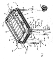
Figure 3 is an exploded perspective view of the frame means according to the invention; -
Figure 4 is a section taken along a vertical plane of profiled element means suitable for being used to obtain the carriage means ofFigure 2 ; -
Figure 5 is a section taken along a vertical plane of further profiled element means suitable for being used to obtain the frame means ofFigure 3 ; -
Figure 6 is a side view of connecting means suitable for mutually interconnecting the further profiled element means to obtain the frame means according to the invention; -
Figure 7 is a side view of locking means associatable with the connecting means ofFigure 6 and suitable for fixing supporting foot means of the machine to the connecting means; -
Figure 8 is a side view of the machine ofFigure 1 , in a work. configuration; -
Figure 9 is a view like that ofFigure 8 , showing the machine in a transport configuration. -
Figures 1 to 9 show a cutting machine for building 1 that is particularly suitable for cutting building products such as tiles, stones, stone material, bricks and the like. - The machine 1 comprises a
frame 2 to which cutting means 3 can be fixed that are provided with ablade 6 suitable for cutting said products. - The machine 1 further comprises a
carriage 4 slidable onguides 5 that are connected to theframe 2, saidcarriage 4 being suitable for supporting said building products to move them towards or away from theblade 6. - The cutting means 3 may be placed in a first work position in which the
blade 6 is arranged substantially perpendicularly to the plane identified by thecarriage 4, and in a second work position in which theblade 6 forms an angle of approximately 45° with respect to the plane defined by thecarriage 4. - The machine 1 further comprises a
tank 24 associated to the bottom of theframe 2 and suitable for collecting the water used during cutting operations for cooling and keeping clean theblade 6. - As
Figure 2 shows, thecarriage 4 comprises a supportingelement 7 for supporting a building product to be cut, with which slidingmeans 8 is associated provided withwheels 9 suitable for engaging with theguides 5. - The
carriage 4 further comprises, at one end thereof, aplate 10 that acts as supporting stop for the building products and with which aruler 11 is associated, saidruler 11 acting as reference for a cutting operator. - The
carriage 4 further comprises, at a further end thereof opposite to said end,closing means 56 arranged for preventing water and/or dirt from penetrating inside the supportingelement 7. - The
carriage 4 further comprises aprotractor 12 that enables said products to be cut according to inclined planes. - The supporting
element 7 is made from a profiledelement 13 that is advantageously obtained in aluminium by extrusion. - With reference to
Figure 4 , the profiledelement 13 comprises a pair oflongitudinal grooves element 13 and suitable for receiving fixing means 74 of the slidingmeans 8. - The
grooves opposite end regions face 13a of the profiledelement 13. - The profiled
element 13 further comprisesprotrusions face 13a, each of saidprotrusions grooves means 8 from shifting once it has been fixed to the profiledelement 13. - The profiled
element 13 further comprises acavity 18 obtained on afurther face 13b, opposite to theface 13a, substantially in the middle of the profiledelement 13. - The
cavity 18 is shaped in such a way as to receive a sharpened end of theblade 6, when the latter is in the first operating position described above. - The profiled
element 13 is further provided with afurther cavity 19 obtained on thefurther face 13b that is substantially tilted by 45° with respect to the plane identified by the profiledelement 13. - The
further cavity 19 is therefore suitable for receiving the sharpened end of the blade when the latter is in the second operating position described above. - The
cavity 18 and thefurther cavity 19 are shaped in such a way as to as to extend along the entire length of the profiledelement 13. - The profiled
element 13 further comprises, on thefurther face 13b, in theopposite end regions further grooves element 13. - The
further grooves tank 24. - Furthermore, on the
further face 13b of the profiledelement 13slots 25 are obtained that are equidistant from one another, which are preferably arranged at distance of one centimetre from one another, which act as indicator means for a cutting operator. - The profiled
element 13 is internally provided withribs 26 that define a plurality ofseats 27 arranged for receiving screws suitable for fixing theplate 10 to the profiledelement 13. - The profiled
element 13 further comprises afurther rib 28 positioned at thecavity 18 and which partially protrudes from theface 13a. - The
further rib 28 constitutes a supporting element cooperating with theprotrusions element 13, when the latter is ejected from the extrusion unit. - With reference to
Figure 3 , theframe 2 consists of afirst part 29, asecond part 30, athird part 31 and afourth part 32 of a further profiledelement 33. - Advantageously, the further profiled
element 33 is made of extruded aluminium. - The
first part 29, thesecond part 30, thethird part 31 and thefourth part 32 are connected together to form arim 36 that has a substantially rectangular shape, at the top of which there is connectingmeans 34 provided with fixing screws 35. - With reference to
Figure 5 , the further profiledelement 33 comprises arib 37 and afurther rib 38 that define inside said further profiledelement 33 afirst chamber 45, asecond chamber 46 and athird chamber 47 arranged for receiving appendices 39 (Figure 6 ) of the connectingmeans 34, as will be described in detail below. - The
rib 37 and thefurther rib 38 define arespective seat screw 35. - The further profiled
element 33 further comprises agroove 42 extending longitudinally therein, saidgroove 42 opening onto aface 33a of the further profiledelement 33 and being suitable for receiving fixing means 43 suitable for fixing theguides 5. - The fixing means 43 comprises
screws 44 the head of which are suitable for being laterally inserted inside thegroove 42 and for being shapingly received in saidgroove 42. - The fixing means 43, before the
screws 44 are tightened, can be moved along thegroove 42 in such a way as to adjust the distance that separates theguide 5. - The use of the further profiled
element 33 according to the invention therefore enables frames to be made that can be associated with carriages of dimensions belonging to a wide range of sizes, by simply adjusting the reciprocal distance between theguides 5 in such a way that they can be slidably coupled to the wheels of said carriages. - The use of screws slidable inside the
groove 42 further enables theblade 6 and thecarriage 4 to be easily assembled in perfect reciprocal alignment. - In this way, the
blade 6 is received during cutting operations inside thecavity 18, or inside thefurther cavity 19. - The
groove 42 is further suitable for receiving connecting means of a band, which is not shown, that promotes the conveying of the cooling and washing water inside thetank 24. - Advantageously, said band is made from partially flexible plastic material and has a bottom strip that can be superimposed on a side wall of the
tank 24 to promote drainage of the water. - The further profiled
element 33 is further provided, on afurther face 33b thereof, opposite to theface 33a, with a pair ofthroats - The
throats throat 48 is positioned at a vertical height higher than the height of thethroat 49, saidthroats - Advantageously, for fixing the cutting means 3 it is not necessary to obtain holes in the frame 2: said fixing element is in fact made to slide along the further profiled
element 33 until it reaches a desired position wherein it can be locked by tightening the screws with which it is provided. - The further profiled
element 33 further comprises, on a stillfurther face 33c, that is substantially perpendicular to theface 33a and to thefurther face 33b, afurther groove 48a arranged for receiving fixing screw means 49a of stacking promoter means 50 shown inFigure 3 . - As will be explained in greater detail below, the machine 1 comprises supporting
feet 52 that can be transferred from an operating position, shown inFigure 3 , in which the supporting feet project below theframe 2, in such a way that ends 53 thereof can be positioned on a supportingplane 77 underneath, to a rest position, in which the supportingfeet 52 are caused to slide with respect to theframe 2 until they protrude above theframe 2. - In such rest position, two or more machines 1 can be advantageously stacked to minimise space occupied by said machines.
- For this purpose, the stacking promoter means 50 comprises beaker means 51 arranged for receiving
further ends 53a, opposite to the aforesaid ends 53, of the supporting feet of a further machine 1, thus substantially preventing the shifting of one machine with respect to the other. - The further profiled
element 33 further comprises ashelf 54, that substantially extends perpendicularly to thewall 33a and acts as a supporting element for thetank 24. - Alternatively, the
tank 24 can be fixed to theframe 2 by connecting means that are engaged in thefurther groove 48a. - The further profiled
element 33 is further provided, at the edge defined by theface 33a and by the still further face 33c, with aprotuberance 55 that acts as a gutter to promote the fall into thetank 24 of drops of water descending along theface 33a, if the tank is connected to theframe 2 at thefurther groove 48a. - As
Figures 3 and6 show, the connectingmeans 34 comprises body means 57, made of metal, advantageously obtained by casting, comprising a pair ofwalls element 33 that are to be interconnected to obtain theframe 2. - In the
walls seats element 33. -
Appendices 39 extend from thewalls first chamber 45, in thesecond chamber 46 and in thethird chamber 47 of the further profiledelement 33, saidappendices 39 acting as stiffing elements of the structure of theframe 2. In the body means 57compartments 60 are defined arranged for receiving supportingfeet 52 of the machine 1. - The supporting
feet 52 can slide inside thecompartments 60 to be transferred between the operating position and the rest position that have been described above. - Advantageously, the
compartments 60 extend obliquely with respect to the plane defined by theframe 2, in such a way that the supportingfeet 52 diverge reciprocally in the operating position, to improve the stability of the machine 1, and converge reciprocally in the rest position, to minimise the space occupied by the machine 1. - Locking means 61 is associated to the body means 57 to prevent the supporting
foot 52 from sliding inside thecompartment 60 when the supportingfoot 52 is in the aforesaid operating position, or in the aforesaid rest position. - The locking means 61 comprises a
lever 62 that controls apresser roller 63 interacting with the supportingfoot 52 to press the supportingfoot 52 against the walls of thecompartment 60. - The presser roller is provided with a
longitudinal hole 64 suitable for receiving apin 65 engagingholes 66 obtained in projectingportions 67 of the body means 57. - The
longitudinal hole 64 is not coaxial with thepresser roller 63, thepresser roller 52 is therefore associated with the body means 57 in such a way as to be eccentric. - The body means 57 is further provided with an
opening 68 through which anend portion 69 of thelever 62 can pass to engagefurther openings 70 obtained in longitudinally consecutive sections of the supportingfoot 52. - In this way, the
end portion 69 is inserted inside theopening 68 and thefurther openings 70 and thereby performs further locking in addition to that achieved by theeccentric presser roller 63. - The machine 1 can be further provided with
handles 72 that make lifting and subsequent transfer simpler. - The
handles 72 can be fixed to theframe 2 through hook means 73 suitable for being received inside thethroats element 33. - As shown is
Figures 8 and 9 ,wheels 71 can be associated to the supportingfeet 52, saidwheels 71 promotes transferring of the machine 1. - Advantageously, the
wheels 71 are associated to two of the four supportingfeet 52 of the machine 1, for example to the supportingfeet 52 arranged in the front part of the machine 1. Thewheels 71 are rotatably supported by sleeve means 75 slidable on the supportingfeet 52. - The sleeve means 75 is provided with a threaded hole suitable for receiving a locking
screw 76 arranged for being pressed against a supportingfoot 52. In this way, the sleeve means 75 is caused to slide along the supportingfeet 52 until it reaches a preset position, subsequently the sleeve means 75 is fixed to said position by adjusting thelock screw 76. - As shown in
Figure 8 , the machine 1 can achieve an operating configuration A in which the ends 53 of the supportingfeet 52 and thebottom portions 71a of thewheels 71 are in contact with the supportingplane 77. - In said operating configuration A, the machine 1 has good stability, which enables precise cutting operations to be performed.
- As Figures shown in 8 and 9, by grasping the
handles 72 and exerting force in the direction of the arrow F, it is possible to cause a rotation R of the machine 1 around pin means 78 that connects thewheels 71 to the sleeve means 75 until the machine 1 is placed in a transport configuration B. - After said rotation, the ends 53 of the supporting
feet 52 are lifted up with respect to the supportingplane 77, in particular not only theends 53 of the supportingfeet 52, to which ends thewheels 71 are not associated, are lifted up, but also theends 53 of the supportingfeet 52, to which thewheels 71 are fixed, are lifted up: this enables transport of the machine 1 to be significantly facilitated inasmuch as it can be. easily transferred by making thewheels 71 slide on the supportingplane 77, saidwheels 71 further supporting a considerable part of the weight of the machine 1.
Claims (12)
- Frame means (2) suitable for being associated with a cutting machine (1) for building, comprising rim means (36) to which carriage means (4) suitable for receiving a product to be cut and cutting means (3) suitable for cutting said product are associatable, said rim means (36) comprising profiled element means (33) that is internally provided with rib means (37, 38) which subdivides said profiled element means (33) into a plurality of chamber means (45, 46, 47), characterized in that said frame means (2) further comprises connecting means (34) connecting a plurality of portions (29, 30, 31, 32) of said profiled element means (33) to obtain said frame means (2), said connecting means being provided with appendices, said plurality of chamber means receiving said appendices, said frame means (2) further comprising supporting foot means (52), said connecting means (34) further comprising compartment means (60) receiving said supporting foot means (52) of said frame means (2) slidable inside said compartment means (60).
- Frame means according to claim 1, wherein said profiled element means (33) comprises seat means (40, 41) arranged for receiving fixing screw means (35) suitable for fixing said connecting means (34) to said profiled element means (33).
- Frame means according to claim 1 or 2, wherein said profiled element means (33) comprises cavity means (42) defined on a face (33a) of said profiled element means, said cavity (42) means being suitable for receiving guide means (5) for guiding said carriage means (4).
- Frame means according to claim 3, wherein said cavity means (42) extends longitudinally along the entire length of said profiled element means (33).
- Frame means according to any one of claims 1 to 4, wherein said profiled element means (33) comprises further cavity means (33b) suitable for receiving fixing means for fixing said cutting means (3) and/or handle means (72) arranged for facilitating the transport of said machine (1).
- Frame means according to claim 5 as appended to claim 3, or 4, wherein said cavity means (42) is defined on a further face (33b) of said profiled element means opposite to said face (33a).
- Frame means according to claim 3, or 4, or according to claim 5 as appended to claim 3, or 4, or according to claim 6, wherein said profiled element means (33) comprises shelf means (54) protruding from said face (33a) and suitable for supporting collection tank means (24) associatable to the bottom of said frame means (2).
- Frame means according to any one of preceding claims, wherein said connecting means (34) comprises a body (57) obtained by casting a metal material.
- Frame means according to any one of claims 1 to 8, wherein said compartment means (60) extends obliquely with respect to a plane defined by said frame means (2), in such a way that said supporting foot means (52) diverges reciprocally in an operating position in which said supporting foot means (52) projects below said frame means (2) and converges reciprocally in a rest position, in which said supporting foot means (52) projects above said frame means (2).
- Frame means according to any one of claims 1 to 9, wherein locking means (61) is associated to said connecting means (34), said locking means (61) being arranged for locking said supporting foot means (52) of said machine (1) inside said compartment means (60).
- Frame means according to claim 10, wherein said locking means (61) comprises eccentric locking means (63).
- Frame means according to any one of claims 3 to 11, wherein said profiled element means (33) further comprises, on a still further face (33c) arranged transversally with respect to said face (33a), further groove means (48a) arranged for receiving container means (51) suitable for containing ends (53a) of said supporting foot means (52) of a further machine (1) positioned on said machine (1).
Applications Claiming Priority (2)
| Application Number | Priority Date | Filing Date | Title |
|---|---|---|---|
| IT2002MO000124A ITMO20020124A1 (en) | 2002-05-16 | 2002-05-16 | CUTTING MACHINE FOR BUILDING |
| ITMO20020124 | 2002-05-16 |
Publications (2)
| Publication Number | Publication Date |
|---|---|
| EP1424160A1 EP1424160A1 (en) | 2004-06-02 |
| EP1424160B1 true EP1424160B1 (en) | 2014-07-09 |
Family
ID=11451037
Family Applications (1)
| Application Number | Title | Priority Date | Filing Date |
|---|---|---|---|
| EP03009781.0A Expired - Lifetime EP1424160B1 (en) | 2002-05-16 | 2003-05-08 | Cutting machine |
Country Status (3)
| Country | Link |
|---|---|
| EP (1) | EP1424160B1 (en) |
| ES (1) | ES2500291T3 (en) |
| IT (1) | ITMO20020124A1 (en) |
Families Citing this family (5)
| Publication number | Priority date | Publication date | Assignee | Title |
|---|---|---|---|---|
| US10603819B2 (en) * | 2015-12-16 | 2020-03-31 | Black & Decker Inc. | Tile saw |
| CN112809946A (en) * | 2021-01-14 | 2021-05-18 | 北京中冀建设有限公司 | Interior decoration ceramic tile positioning cutting machine |
| CN114453652B (en) * | 2022-01-19 | 2023-09-19 | 青岛科技大学 | An intelligent automated processing platform for electromechanical equipment |
| EP4397446A1 (en) * | 2023-01-03 | 2024-07-10 | J. Michael Mehltretter | Vibration-resistant machine frame with aluminium profiles |
| CN120228331B (en) * | 2025-05-30 | 2025-08-19 | 常州市武进三维电子有限公司 | Cutting device and method for processing multilayer thermoelectric separation copper substrate |
Family Cites Families (4)
| Publication number | Priority date | Publication date | Assignee | Title |
|---|---|---|---|---|
| DE1193888B (en) | 1959-12-10 | 1965-05-26 | Rolf Susemihl | Multipurpose work device |
| DE9005568U1 (en) * | 1990-05-16 | 1991-09-12 | Robert Bosch Gmbh, 7000 Stuttgart | Carrier plate |
| DE29903633U1 (en) * | 1999-03-01 | 1999-07-29 | Schelkle, Karl Anton, 88525 Dürmentingen | Saw table for cutting wooden parts using a commercially available circular saw |
| DE20107761U1 (en) | 2001-05-08 | 2001-08-02 | Durq Machinery Corp., Taichung | Workbench |
-
2002
- 2002-05-16 IT IT2002MO000124A patent/ITMO20020124A1/en unknown
-
2003
- 2003-05-08 ES ES03009781.0T patent/ES2500291T3/en not_active Expired - Lifetime
- 2003-05-08 EP EP03009781.0A patent/EP1424160B1/en not_active Expired - Lifetime
Also Published As
| Publication number | Publication date |
|---|---|
| EP1424160A1 (en) | 2004-06-02 |
| ES2500291T3 (en) | 2014-09-30 |
| ITMO20020124A0 (en) | 2002-05-16 |
| ITMO20020124A1 (en) | 2003-11-17 |
Similar Documents
| Publication | Publication Date | Title |
|---|---|---|
| US6901832B2 (en) | Method and apparatus to remove pieces cut from a bar-shaped workpiece with a cutting machine | |
| KR102074505B1 (en) | Side cutting machine for wooden doors | |
| EP1424160A1 (en) | Cutting machine | |
| US4100949A (en) | Web forming apparatus | |
| US4409875A (en) | Apparatus for manufacturing an integral wooden angle bar | |
| HK1066503A (en) | Cutting machine | |
| CN213918723U (en) | Automatic unloader that goes up of panel hot pressing | |
| KR200210562Y1 (en) | Automatic carrying construction structure of amputation wood | |
| CN210757964U (en) | Transverse and longitudinal cutting multifunctional sliding table saw | |
| CN217514089U (en) | Automatic saw bamboo discernment conveying equipment | |
| CA2256968C (en) | Pallet retention and release system | |
| KR102572900B1 (en) | Corrugated side wall cutting device for corrugated side wall conveyor belt | |
| CN214871333U (en) | Automatic saw system | |
| CN111168786A (en) | Multi-functional plank grooving device in batches | |
| EP1118438B1 (en) | Chopping machine for cutting and splitting timber | |
| CN214732793U (en) | Plank material feeding unit | |
| CN211869473U (en) | Jean conveying device | |
| CN114683041A (en) | Mechanical automation decides equipment | |
| CN210884171U (en) | Automatic feeding device of punching and cutting integrated machine | |
| JP4724821B2 (en) | Meat slicer | |
| CN217621144U (en) | Be applied to screening transmission device on automatic saw bamboo discernment conveying production line | |
| CN222806603U (en) | A scrap steel shearing device with reversible discharging | |
| KR102367930B1 (en) | Cutting machine with upper pressing part | |
| CN220464198U (en) | Novel saw pushing table | |
| CN218838038U (en) | Cross cutting machine product collection device |
Legal Events
| Date | Code | Title | Description |
|---|---|---|---|
| PUAI | Public reference made under article 153(3) epc to a published international application that has entered the european phase |
Free format text: ORIGINAL CODE: 0009012 |
|
| AK | Designated contracting states |
Kind code of ref document: A1 Designated state(s): AT BE BG CH CY CZ DE DK EE ES FI FR GB GR HU IE IT LI LU MC NL PT RO SE SI SK TR |
|
| AX | Request for extension of the european patent |
Extension state: AL LT LV MK SI |
|
| 17P | Request for examination filed |
Effective date: 20041018 |
|
| AKX | Designation fees paid |
Designated state(s): AT BE BG CH CY CZ DE DK EE ES FI FR GB GR HU IE IT LI LU MC NL PT RO SE SI SK TR |
|
| REG | Reference to a national code |
Ref country code: HK Ref legal event code: DE Ref document number: 1066503 Country of ref document: HK |
|
| 17Q | First examination report despatched |
Effective date: 20091125 |
|
| GRAP | Despatch of communication of intention to grant a patent |
Free format text: ORIGINAL CODE: EPIDOSNIGR1 |
|
| REG | Reference to a national code |
Ref country code: HK Ref legal event code: WD Ref document number: 1066503 Country of ref document: HK |
|
| INTG | Intention to grant announced |
Effective date: 20131203 |
|
| GRAS | Grant fee paid |
Free format text: ORIGINAL CODE: EPIDOSNIGR3 |
|
| RIN1 | Information on inventor provided before grant (corrected) |
Inventor name: TONDINI, CLAUDIO |
|
| GRAA | (expected) grant |
Free format text: ORIGINAL CODE: 0009210 |
|
| AK | Designated contracting states |
Kind code of ref document: B1 Designated state(s): AT BE BG CH CY CZ DE DK EE ES FI FR GB GR HU IE IT LI LU MC NL PT RO SE SI SK TR |
|
| REG | Reference to a national code |
Ref country code: GB Ref legal event code: FG4D |
|
| REG | Reference to a national code |
Ref country code: CH Ref legal event code: EP Ref country code: AT Ref legal event code: REF Ref document number: 676391 Country of ref document: AT Kind code of ref document: T Effective date: 20140715 |
|
| REG | Reference to a national code |
Ref country code: IE Ref legal event code: FG4D |
|
| REG | Reference to a national code |
Ref country code: DE Ref legal event code: R096 Ref document number: 60346447 Country of ref document: DE Effective date: 20140814 |
|
| REG | Reference to a national code |
Ref country code: ES Ref legal event code: FG2A Ref document number: 2500291 Country of ref document: ES Kind code of ref document: T3 Effective date: 20140930 |
|
| REG | Reference to a national code |
Ref country code: NL Ref legal event code: VDEP Effective date: 20140709 |
|
| PG25 | Lapsed in a contracting state [announced via postgrant information from national office to epo] |
Ref country code: GR Free format text: LAPSE BECAUSE OF FAILURE TO SUBMIT A TRANSLATION OF THE DESCRIPTION OR TO PAY THE FEE WITHIN THE PRESCRIBED TIME-LIMIT Effective date: 20141010 Ref country code: FI Free format text: LAPSE BECAUSE OF FAILURE TO SUBMIT A TRANSLATION OF THE DESCRIPTION OR TO PAY THE FEE WITHIN THE PRESCRIBED TIME-LIMIT Effective date: 20140709 Ref country code: SE Free format text: LAPSE BECAUSE OF FAILURE TO SUBMIT A TRANSLATION OF THE DESCRIPTION OR TO PAY THE FEE WITHIN THE PRESCRIBED TIME-LIMIT Effective date: 20140709 Ref country code: PT Free format text: LAPSE BECAUSE OF FAILURE TO SUBMIT A TRANSLATION OF THE DESCRIPTION OR TO PAY THE FEE WITHIN THE PRESCRIBED TIME-LIMIT Effective date: 20141110 Ref country code: BG Free format text: LAPSE BECAUSE OF FAILURE TO SUBMIT A TRANSLATION OF THE DESCRIPTION OR TO PAY THE FEE WITHIN THE PRESCRIBED TIME-LIMIT Effective date: 20141009 |
|
| PG25 | Lapsed in a contracting state [announced via postgrant information from national office to epo] |
Ref country code: NL Free format text: LAPSE BECAUSE OF FAILURE TO SUBMIT A TRANSLATION OF THE DESCRIPTION OR TO PAY THE FEE WITHIN THE PRESCRIBED TIME-LIMIT Effective date: 20140709 Ref country code: CY Free format text: LAPSE BECAUSE OF FAILURE TO SUBMIT A TRANSLATION OF THE DESCRIPTION OR TO PAY THE FEE WITHIN THE PRESCRIBED TIME-LIMIT Effective date: 20140709 |
|
| REG | Reference to a national code |
Ref country code: DE Ref legal event code: R097 Ref document number: 60346447 Country of ref document: DE |
|
| PG25 | Lapsed in a contracting state [announced via postgrant information from national office to epo] |
Ref country code: SK Free format text: LAPSE BECAUSE OF FAILURE TO SUBMIT A TRANSLATION OF THE DESCRIPTION OR TO PAY THE FEE WITHIN THE PRESCRIBED TIME-LIMIT Effective date: 20140709 Ref country code: CZ Free format text: LAPSE BECAUSE OF FAILURE TO SUBMIT A TRANSLATION OF THE DESCRIPTION OR TO PAY THE FEE WITHIN THE PRESCRIBED TIME-LIMIT Effective date: 20140709 Ref country code: DK Free format text: LAPSE BECAUSE OF FAILURE TO SUBMIT A TRANSLATION OF THE DESCRIPTION OR TO PAY THE FEE WITHIN THE PRESCRIBED TIME-LIMIT Effective date: 20140709 Ref country code: RO Free format text: LAPSE BECAUSE OF FAILURE TO SUBMIT A TRANSLATION OF THE DESCRIPTION OR TO PAY THE FEE WITHIN THE PRESCRIBED TIME-LIMIT Effective date: 20140709 Ref country code: EE Free format text: LAPSE BECAUSE OF FAILURE TO SUBMIT A TRANSLATION OF THE DESCRIPTION OR TO PAY THE FEE WITHIN THE PRESCRIBED TIME-LIMIT Effective date: 20140709 |
|
| PLBE | No opposition filed within time limit |
Free format text: ORIGINAL CODE: 0009261 |
|
| STAA | Information on the status of an ep patent application or granted ep patent |
Free format text: STATUS: NO OPPOSITION FILED WITHIN TIME LIMIT |
|
| 26N | No opposition filed |
Effective date: 20150410 |
|
| PG25 | Lapsed in a contracting state [announced via postgrant information from national office to epo] |
Ref country code: SI Free format text: LAPSE BECAUSE OF FAILURE TO SUBMIT A TRANSLATION OF THE DESCRIPTION OR TO PAY THE FEE WITHIN THE PRESCRIBED TIME-LIMIT Effective date: 20140709 |
|
| REG | Reference to a national code |
Ref country code: CH Ref legal event code: PL |
|
| GBPC | Gb: european patent ceased through non-payment of renewal fee |
Effective date: 20150508 |
|
| PG25 | Lapsed in a contracting state [announced via postgrant information from national office to epo] |
Ref country code: LI Free format text: LAPSE BECAUSE OF NON-PAYMENT OF DUE FEES Effective date: 20150531 Ref country code: LU Free format text: LAPSE BECAUSE OF FAILURE TO SUBMIT A TRANSLATION OF THE DESCRIPTION OR TO PAY THE FEE WITHIN THE PRESCRIBED TIME-LIMIT Effective date: 20150508 Ref country code: MC Free format text: LAPSE BECAUSE OF FAILURE TO SUBMIT A TRANSLATION OF THE DESCRIPTION OR TO PAY THE FEE WITHIN THE PRESCRIBED TIME-LIMIT Effective date: 20140709 Ref country code: CH Free format text: LAPSE BECAUSE OF NON-PAYMENT OF DUE FEES Effective date: 20150531 |
|
| REG | Reference to a national code |
Ref country code: IE Ref legal event code: MM4A |
|
| REG | Reference to a national code |
Ref country code: FR Ref legal event code: ST Effective date: 20160129 |
|
| PG25 | Lapsed in a contracting state [announced via postgrant information from national office to epo] |
Ref country code: IE Free format text: LAPSE BECAUSE OF NON-PAYMENT OF DUE FEES Effective date: 20150508 Ref country code: GB Free format text: LAPSE BECAUSE OF NON-PAYMENT OF DUE FEES Effective date: 20150508 |
|
| PG25 | Lapsed in a contracting state [announced via postgrant information from national office to epo] |
Ref country code: FR Free format text: LAPSE BECAUSE OF NON-PAYMENT OF DUE FEES Effective date: 20150601 |
|
| PG25 | Lapsed in a contracting state [announced via postgrant information from national office to epo] |
Ref country code: BE Free format text: LAPSE BECAUSE OF FAILURE TO SUBMIT A TRANSLATION OF THE DESCRIPTION OR TO PAY THE FEE WITHIN THE PRESCRIBED TIME-LIMIT Effective date: 20140709 |
|
| PG25 | Lapsed in a contracting state [announced via postgrant information from national office to epo] |
Ref country code: HU Free format text: LAPSE BECAUSE OF FAILURE TO SUBMIT A TRANSLATION OF THE DESCRIPTION OR TO PAY THE FEE WITHIN THE PRESCRIBED TIME-LIMIT; INVALID AB INITIO Effective date: 20030508 |
|
| PG25 | Lapsed in a contracting state [announced via postgrant information from national office to epo] |
Ref country code: TR Free format text: LAPSE BECAUSE OF FAILURE TO SUBMIT A TRANSLATION OF THE DESCRIPTION OR TO PAY THE FEE WITHIN THE PRESCRIBED TIME-LIMIT Effective date: 20140709 |
|
| PGFP | Annual fee paid to national office [announced via postgrant information from national office to epo] |
Ref country code: DE Payment date: 20210527 Year of fee payment: 19 Ref country code: IT Payment date: 20210519 Year of fee payment: 19 |
|
| PGFP | Annual fee paid to national office [announced via postgrant information from national office to epo] |
Ref country code: AT Payment date: 20210421 Year of fee payment: 19 Ref country code: ES Payment date: 20210601 Year of fee payment: 19 |
|
| REG | Reference to a national code |
Ref country code: DE Ref legal event code: R119 Ref document number: 60346447 Country of ref document: DE |
|
| REG | Reference to a national code |
Ref country code: AT Ref legal event code: MM01 Ref document number: 676391 Country of ref document: AT Kind code of ref document: T Effective date: 20220508 |
|
| PG25 | Lapsed in a contracting state [announced via postgrant information from national office to epo] |
Ref country code: AT Free format text: LAPSE BECAUSE OF NON-PAYMENT OF DUE FEES Effective date: 20220508 |
|
| PG25 | Lapsed in a contracting state [announced via postgrant information from national office to epo] |
Ref country code: DE Free format text: LAPSE BECAUSE OF NON-PAYMENT OF DUE FEES Effective date: 20221201 |
|
| REG | Reference to a national code |
Ref country code: ES Ref legal event code: FD2A Effective date: 20230627 |
|
| PG25 | Lapsed in a contracting state [announced via postgrant information from national office to epo] |
Ref country code: IT Free format text: LAPSE BECAUSE OF NON-PAYMENT OF DUE FEES Effective date: 20220508 Ref country code: ES Free format text: LAPSE BECAUSE OF NON-PAYMENT OF DUE FEES Effective date: 20220509 |