EP1423283B1 - Droplet deposition apparatus - Google Patents
Droplet deposition apparatus Download PDFInfo
- Publication number
- EP1423283B1 EP1423283B1 EP02758571A EP02758571A EP1423283B1 EP 1423283 B1 EP1423283 B1 EP 1423283B1 EP 02758571 A EP02758571 A EP 02758571A EP 02758571 A EP02758571 A EP 02758571A EP 1423283 B1 EP1423283 B1 EP 1423283B1
- Authority
- EP
- European Patent Office
- Prior art keywords
- support
- support according
- ink
- wall section
- manifolds
- Prior art date
- Legal status (The legal status is an assumption and is not a legal conclusion. Google has not performed a legal analysis and makes no representation as to the accuracy of the status listed.)
- Expired - Lifetime
Links
- 230000008021 deposition Effects 0.000 title description 2
- 239000000463 material Substances 0.000 claims abstract description 31
- 238000012546 transfer Methods 0.000 claims abstract description 23
- 239000012530 fluid Substances 0.000 claims abstract description 17
- 230000001413 cellular effect Effects 0.000 claims abstract description 3
- 239000004033 plastic Substances 0.000 claims description 8
- 229920003023 plastic Polymers 0.000 claims description 8
- 229910052751 metal Inorganic materials 0.000 claims description 6
- 239000002184 metal Substances 0.000 claims description 6
- 239000000919 ceramic Substances 0.000 claims description 4
- 238000004891 communication Methods 0.000 claims description 4
- 239000004020 conductor Substances 0.000 claims description 3
- 239000007788 liquid Substances 0.000 claims description 3
- 238000007788 roughening Methods 0.000 claims description 3
- 230000002401 inhibitory effect Effects 0.000 claims description 2
- 238000007493 shaping process Methods 0.000 claims 2
- 239000004411 aluminium Substances 0.000 description 12
- 229910052782 aluminium Inorganic materials 0.000 description 12
- XAGFODPZIPBFFR-UHFFFAOYSA-N aluminium Chemical compound [Al] XAGFODPZIPBFFR-UHFFFAOYSA-N 0.000 description 12
- 238000009413 insulation Methods 0.000 description 6
- 238000007639 printing Methods 0.000 description 6
- 238000004519 manufacturing process Methods 0.000 description 4
- 238000003491 array Methods 0.000 description 3
- 238000009826 distribution Methods 0.000 description 3
- 238000000034 method Methods 0.000 description 3
- 238000000465 moulding Methods 0.000 description 3
- 239000006260 foam Substances 0.000 description 2
- 239000012212 insulator Substances 0.000 description 2
- 125000006850 spacer group Chemical group 0.000 description 2
- 238000002679 ablation Methods 0.000 description 1
- 230000002411 adverse Effects 0.000 description 1
- 230000003466 anti-cipated effect Effects 0.000 description 1
- 230000004888 barrier function Effects 0.000 description 1
- 230000009286 beneficial effect Effects 0.000 description 1
- 238000005266 casting Methods 0.000 description 1
- 210000003850 cellular structure Anatomy 0.000 description 1
- 230000008859 change Effects 0.000 description 1
- 239000011248 coating agent Substances 0.000 description 1
- 238000000576 coating method Methods 0.000 description 1
- 238000001816 cooling Methods 0.000 description 1
- 238000013461 design Methods 0.000 description 1
- 238000010586 diagram Methods 0.000 description 1
- 230000000694 effects Effects 0.000 description 1
- 230000005684 electric field Effects 0.000 description 1
- 238000005530 etching Methods 0.000 description 1
- 238000001125 extrusion Methods 0.000 description 1
- 238000010304 firing Methods 0.000 description 1
- 229920001821 foam rubber Polymers 0.000 description 1
- 230000017525 heat dissipation Effects 0.000 description 1
- 238000010438 heat treatment Methods 0.000 description 1
- 230000004048 modification Effects 0.000 description 1
- 238000012986 modification Methods 0.000 description 1
- 239000002991 molded plastic Substances 0.000 description 1
- 239000002245 particle Substances 0.000 description 1
- 239000000126 substance Substances 0.000 description 1
Images


Classifications
-
- B—PERFORMING OPERATIONS; TRANSPORTING
- B41—PRINTING; LINING MACHINES; TYPEWRITERS; STAMPS
- B41J—TYPEWRITERS; SELECTIVE PRINTING MECHANISMS, i.e. MECHANISMS PRINTING OTHERWISE THAN FROM A FORME; CORRECTION OF TYPOGRAPHICAL ERRORS
- B41J2/00—Typewriters or selective printing mechanisms characterised by the printing or marking process for which they are designed
- B41J2/005—Typewriters or selective printing mechanisms characterised by the printing or marking process for which they are designed characterised by bringing liquid or particles selectively into contact with a printing material
- B41J2/01—Ink jet
- B41J2/17—Ink jet characterised by ink handling
- B41J2/175—Ink supply systems ; Circuit parts therefor
-
- B—PERFORMING OPERATIONS; TRANSPORTING
- B41—PRINTING; LINING MACHINES; TYPEWRITERS; STAMPS
- B41J—TYPEWRITERS; SELECTIVE PRINTING MECHANISMS, i.e. MECHANISMS PRINTING OTHERWISE THAN FROM A FORME; CORRECTION OF TYPOGRAPHICAL ERRORS
- B41J2/00—Typewriters or selective printing mechanisms characterised by the printing or marking process for which they are designed
- B41J2/005—Typewriters or selective printing mechanisms characterised by the printing or marking process for which they are designed characterised by bringing liquid or particles selectively into contact with a printing material
- B41J2/01—Ink jet
- B41J2/135—Nozzles
- B41J2/145—Arrangement thereof
- B41J2/155—Arrangement thereof for line printing
-
- B—PERFORMING OPERATIONS; TRANSPORTING
- B41—PRINTING; LINING MACHINES; TYPEWRITERS; STAMPS
- B41J—TYPEWRITERS; SELECTIVE PRINTING MECHANISMS, i.e. MECHANISMS PRINTING OTHERWISE THAN FROM A FORME; CORRECTION OF TYPOGRAPHICAL ERRORS
- B41J2/00—Typewriters or selective printing mechanisms characterised by the printing or marking process for which they are designed
- B41J2/005—Typewriters or selective printing mechanisms characterised by the printing or marking process for which they are designed characterised by bringing liquid or particles selectively into contact with a printing material
- B41J2/01—Ink jet
- B41J2/135—Nozzles
- B41J2/14—Structure thereof only for on-demand ink jet heads
- B41J2002/14419—Manifold
-
- B—PERFORMING OPERATIONS; TRANSPORTING
- B41—PRINTING; LINING MACHINES; TYPEWRITERS; STAMPS
- B41J—TYPEWRITERS; SELECTIVE PRINTING MECHANISMS, i.e. MECHANISMS PRINTING OTHERWISE THAN FROM A FORME; CORRECTION OF TYPOGRAPHICAL ERRORS
- B41J2202/00—Embodiments of or processes related to ink-jet or thermal heads
- B41J2202/01—Embodiments of or processes related to ink-jet heads
- B41J2202/08—Embodiments of or processes related to ink-jet heads dealing with thermal variations, e.g. cooling
-
- B—PERFORMING OPERATIONS; TRANSPORTING
- B41—PRINTING; LINING MACHINES; TYPEWRITERS; STAMPS
- B41J—TYPEWRITERS; SELECTIVE PRINTING MECHANISMS, i.e. MECHANISMS PRINTING OTHERWISE THAN FROM A FORME; CORRECTION OF TYPOGRAPHICAL ERRORS
- B41J2202/00—Embodiments of or processes related to ink-jet or thermal heads
- B41J2202/01—Embodiments of or processes related to ink-jet heads
- B41J2202/12—Embodiments of or processes related to ink-jet heads with ink circulating through the whole print head
-
- B—PERFORMING OPERATIONS; TRANSPORTING
- B41—PRINTING; LINING MACHINES; TYPEWRITERS; STAMPS
- B41J—TYPEWRITERS; SELECTIVE PRINTING MECHANISMS, i.e. MECHANISMS PRINTING OTHERWISE THAN FROM A FORME; CORRECTION OF TYPOGRAPHICAL ERRORS
- B41J2202/00—Embodiments of or processes related to ink-jet or thermal heads
- B41J2202/01—Embodiments of or processes related to ink-jet heads
- B41J2202/19—Assembling head units
Definitions
- the present invention relates to printers and in particular droplet deposition ink jet printers
- Ink jet printers are no longer viewed simply as office printers, their versatility means that they are now used in digital presses and other industrial markets. It is not uncommon for print heads to contain in excess of 500 nozzles and it is anticipated that "page wide" print heads containing over 2000 nozzles will be commercially available in the near future.
- a support suitable for use for a page wide print head is described in WO 00/24584 .
- the support is formed of extruded aluminium and has a footprint of a similar size to that of the print head to which it is attached. This allows a number of arrays to be arranged in parallel to one another at a relatively close spacing. The close spacing is necessary to minimise effects caused by paper travel and to ease alignment.
- WO 00/38928 discloses a support having a similar structure.
- a support of this general nature has a number of useful advantages.
- a print head is mounted to the support of WO 00/24584 and is continually supplied with ink from the ink inlet manifold.
- the print head itself is formed of a number of parallel channels having sidewalls of a piezoelectric material. The sidewalls are polarised such that an applied electric field causes them to deflect in shear and pressurise the ink within the ejection channels.
- EP 0 278 590 and WO 00/29217 describe such an apparatus and consequently it will hot be discussed in any more detail in this application.
- any heat generated by the piezoelectric material is absorbed into the ink and removed from the head.
- the support of the prior art is formed of extruded aluminium and is sized such that there is substantially even distribution of heat along its length. This reduces thermally-induced strains that might otherwise distort the print head. Such distortion would become more pronounced as the width of the print head increases, for example to that of a page (typically 12.6 inches (32cm) for the American "Foolscap” standard) and would occur regardiess of whether a plurality of narrow ejection units or a single wide ejection unit were used in conjunction with the support member.
- the present invention consists in one aspect a support for an of inkjet print head demanding in use a continuous flow of ink, said support providing a mounting surface which is arranged to receive at least one print head and which provides ink inlet and outlet ports for communication with the print head or heads, the support comprising at least two wall sections cooperating to define inlet and outlet ink manifolds, one wall section being thermally conducting so as to promote heat transfer along the length of the support, another wall section being provided with insulating means, said insulating means inhibiting heat transfer between the inlet and outlet manifolds.
- the respective thermally conducting and thermally insulating wall sections are formed from different materials, such as metal and plastics.
- the wall sections are folded with one of the wall sections suitably being U-shaped in the cross section of the support.
- the thermally insulating wall section defines a phase barrier, such as an air filled cavity wall or cellular structure or a trapped layer of ink or other fluid.
- a support apparatus for an inkjet print head said support taking the form of a generally hollow cylinder and defining an ink inlet manifold and an ink outlet manifold each extending parallel to the axis of the support, there being means for insulating said manifolds from each other to reduce heat transfer therebetween.
- the insulating means comprises a wall separating said ink inlet manifold from said ink outlet manifold.
- the arrangement can be such that both the ink inlet manifold and ink outlet manifolds extend substantially the length of the support and are enclosed by a perimeter.
- the perimeter forms at least part of said ink outlet manifold and the wall separating the inlet and outlet manifolds is formed of a material having a lower heat transfer coefficient than said perimeter. This material may be plastic, rigid foam or any other appropriate material.
- the insulating means may be located adjacent at least one side of said wall and may be a material having a lower coefficient of thermal conduction than the remainder of said wall.
- a cavity wall is provided that allows for a greater range of insulation to be used including gasses, other liquids or even a vacuum.
- the fluid material within said cavity can be pressurised and the walls of said cavity wall flexible to accommodate said fluid material over a range of pressures.
- the insulating means comprises a heat sink disposed within one of said manifolds. This extends substantially the entire length of said one of said manifolds and ensures that the heat transfer along the support is significantly greater that the heat transfer between the outlet and inlet manifolds.
- the present invention consists in a support for an inkjet print head demanding in use a continuous flow of ink, said support providing a mounting surface which is arranged to receive at least one print head and which provides ink inlet and outlet ports for communication with the print head or heads, the support comprising at least two wall sections cooperating to define inlet and outlet ink manifolds, one wall section being formed of a thermally conducting material so as to promote heat transfer along the length of the support, another wall section being formed of a different material being thermally insulating so as to inhibit heat transfer between the inlet and outlet manifolds.
- the ink inlet and ink outlet manifolds are fluidically connected through a print head mounted onto the support. It is even more preferable that the fluid connection is through the ejection channels of the print head.
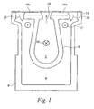
- Figure 1 depicts an ink supply support according to the prior art.
- the support is formed of extruded aluminium and consists of two separate manifolds 2, 4 that extend substantially the length of the support.
- the wall 6 dividing the two manifolds is thus formed of the same material as the exterior wall of the support.
- Ink enters and leaves through ports (not shown) situated at one end of the support.
- the ink flows down the inner manifold 2 in one direction as depicted by the symbol 10 and flows back down the outer manifold in the opposite direction as depicted by the symbol 12.
- the inner and outer manifolds 2, 4 are connected through a print head 14 attached to the top of the support.
- Two arrays of piezoelectric material containing sawn parallel channels 16a, 16b provide the ejection energy. Ink is supplied simultaneously to both arrays from a central manifold in the direction of arrow 18 and returns to the outer manifold of the support after passing through the ejection channel as shown by the arrow 20.
- the ink should enter the support at a well-controlled temperature, pass along the inlet manifold at the same temperature, flow through the channels picking up heat from the PZT, and leave via the outlet manifolds at a uniform but higher temperature.
- Constant temperature waveforms which are applied to the non ejecting channels and cause the PZT to dissipate that part of the heat generated during printing which is not removed by the ejected droplets are used to maintain the temperature within the channels at a constant temperature along the entire array.
- the chips also generate heat, the amount depending on the firing voltage and (to a lesser extent) on the image being printed.
- the chips require cooling and thus have been situated so that this heat finds its way into the outlet manifold 4.
- the aluminium chassis that forms the support provides a conduction path that attempts to equalise temperatures along the array. Ink flow along the array assists in the distribution of heat.
- Heat dissipated by the PZT is of the order of 0.015 W/channel, and the chips dissipate a similar amount. If all of this heat were to go into the ink through flow then the temperature rise of the ink in passing through the PWA would be 5.40C.
- the amount of heat removed during full black printing is 0.0015 W/channel, that is to say a small fraction of the total heat dissipation.
- the removal of heat by the drops is even less significant. Heat losses from the print head to the surroundings are modest and any covers protecting the electronics act to further reduce the heat loss.
- the aluminium chassis has the disadvantageous feature of transferring a significant amount of heat from the outlet manifold to the inlet manifold as well as the advantageous feature of transferring heat along the length of the support.
- the heat transferred through two walls, each 30 mm high and running the length of the array is 52 watts.
- the print head is operating as a counter current heat exchanger, the aluminium chassis and the ink being unable to completely equalise the temperature difference along the array.
- Figure 2 is a graphical representation of the temperature difference along the print head support.
- the support is modified such that the heat transfer coefficient between the ink inlet manifold and the ink outlet manifold is less than that of the prior art.
- the divider separating the two conduits is a wall that is roughened or shaped so as to provide a thick boundary or stagnant layer.
- the ridges 7 can extend either parallel to or perpendicular to the direction of fluid flow. In this case, where the support is extruded, the ridges extend parallel to the direction of fluid flow.
- an insulating coating can be applied to one or both sides of the dividing wall.
- the divider can be formed from the same material as the extruded perimeter. It is of course possible to use other materials as the dividing wall as described in the alternative embodiments of the first embodiment and as depicted in Figures 4 to 7.
- the inlet 9 and outlet 11 manifolds for the print head are formed by etching, sawing or ablation. Because an insert will be attached to the inside of the support to provide the flow features, it is not necessary to manufacture the slots to as high a degree of tolerance as in the aluminium support.
- the features of the manifolds are provided by an insert that acts as an insulator between the inlet 2 and the outlet manifolds 4 as shown in Figure 5.
- the plastic inset 22 is adhesively attached to the upper surface of the supply support 28.
- Spacers 24 are used to ensure there is no adverse movement of the spacer. In certain circumstances it is beneficial to provide baffles, ridges or a roughened surface to increase the boundary layer of ink around the dividing wall and to provide additional insulation.
- a double wall may be formed and which provides an insulating air cavity.
- the plastic wall may be replaced by a closed-cell foam rubber wall, chosen to be resistant to chemical attack by the ink, capable of being formed into an appropriate shape and which does not shed dirt particles into the ink.
- a closed-cell foam rubber wall chosen to be resistant to chemical attack by the ink, capable of being formed into an appropriate shape and which does not shed dirt particles into the ink.
- Other materials are also possible without departing from the scope of the present invention.
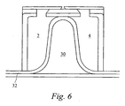
- Figure 6 shows a single row print head formed on a support.
- the piezoelectric material 16a provides a flow circuit between an inlet manifold 2 and an outlet manifold 4.
- the manifolds are separated by a plastic material formed such that there is a cavity 30 between them.
- the cavity is filled with a fluid, preferably gaseous, or a vacuum in order to provide insulation between the two manifolds.
- a fluid preferably gaseous, or a vacuum in order to provide insulation between the two manifolds.
- the dividing wall is attached to the support at least one point and may be rigid or flexible. Where the wall is flexible, a source of pressurised fluid can be used to change the pressures within the manifolds. A 3mm gap of air reduces the difference along a 20cm array to below.
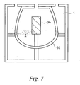
- a further method of improving the distribution of heat along the support, rather than across the walls is to provide a highly conductive heat transfer bar within one of the manifolds as depicted in Figure 7.
- the bar 36 can extend beyond the edge of the support and attached to an external heat exchanger, or alternatively it may be contained fully within the support.
- the heat transfer along the array is increased to the point where the transfer across the divider separating the inlet and outlet manifolds becomes insignificant.
- Figure 8 depicts a further design of manifold that is preferably formed of a moulded material, the manifold component having an inlet 2 and two outlet manifolds 4.
- manifolds are moulded it is possible to mould a double wall dividing the inlet and outlet manifolds.
- the double wall comprises a cavity of air that acts as an insulator reducing the amount of heat transfer across the wall.
- One of the purposes of the manifold component is to receive the heat from the driver chips bonded to its outer surfaces. Where the plastics material of the component has a low thermal conductivity this heat transfer is reduced.
- a metallic, or other higher thermally conductive material 40 may be moulded into the component during manufacture as shown in Figure 9. This allows heat transfer between the chip and the outlet manifold whilst still providing insulation to the inner manifold.
- a hollow, cylindrical support 100 serves to mount a plurality of ink jet print heads 102.
- the support 100 has a external wall section 110, folded into a U-shape.
- the support provides a mounting surface 112 on which are supported the print heads, each of which comprises a layer of piezoelectric material 104 defining ink channels extending across the support and a cover plate 106 defining nozzles 108.
- two ink channels are defined by respective sections 104a and 104b of the piezoelectric layer.
- ink flowing through inlet port 122 in the mounting surface flows continuously in opposing transverse directions through the two ink channels to be collected by respective outlet ports 114.
- the outlet ports 114 communicate with an outlet ink manifold defined by the external wall section 110.
- An internal wall section takes the form of double walls 116 and 118 defining between them a thermally insulating cavity 120.
- This cavity may contain air at atmospheric material, be evacuated or contain trapped ink or other appropriate liquid.
- the cavity may be filled with foam or other cellular material.
- the inlet ink manifold defined by the cavity wall 116,118 communicates with the ink inlet port 122.
- the structure shown in Figure 10 may be formed in one piece by - for example - extrusion or moulding or by a range of other forming techniques.
- the structure is formed of extruded aluminium or other suitable metal.
- the structure is formed of moulded plastic.
- an additional wall section is provided of metal or metal loaded plastic to promote heat transfer along the length of the support.
- the structure is formed from wall sections of different material.
- a port plate (not shown) is interposed between the wall sections and the print heads to assist in defining the ink inlet and outlet ports.
- openings defined with relatively low precision by the cooperating wall sections communicate with more precisely defined port openings in the interposed plate.
- this port plate may form part of the support or part of the print head.
Abstract
Description
- The present invention relates to printers and in particular droplet deposition ink jet printers
- Ink jet printers are no longer viewed simply as office printers, their versatility means that they are now used in digital presses and other industrial markets. It is not uncommon for print heads to contain in excess of 500 nozzles and it is anticipated that "page wide" print heads containing over 2000 nozzles will be commercially available in the near future.
- A support suitable for use for a page wide print head is described in
WO 00/24584 -
WO 00/38928 - A support of this general nature has a number of useful advantages.
- It is an objective of
WO 00/24584 - A print head is mounted to the support of
WO 00/24584 EP 0 277 703EP 0 278 590WO 00/29217 - As the ink flows continually through the channels, any heat generated by the piezoelectric material is absorbed into the ink and removed from the head.
- For ease of manufacture and cost reasons, the support of the prior art is formed of extruded aluminium and is sized such that there is substantially even distribution of heat along its length. This reduces thermally-induced strains that might otherwise distort the print head. Such distortion would become more pronounced as the width of the print head increases, for example to that of a page (typically 12.6 inches (32cm) for the American "Foolscap" standard) and would occur regardiess of whether a plurality of narrow ejection units or a single wide ejection unit were used in conjunction with the support member.
- It is an object of the present invention to further improve thermal management and temperature uniformity along a support and to address other associated problems.
- Accordingly, the present invention consists in one aspect a support for an of inkjet print head demanding in use a continuous flow of ink, said support providing a mounting surface which is arranged to receive at least one print head and which provides ink inlet and outlet ports for communication with the print head or heads, the support comprising at least two wall sections cooperating to define inlet and outlet ink manifolds, one wall section being thermally conducting so as to promote heat transfer along the length of the support, another wall section being provided with insulating means, said insulating means inhibiting heat transfer between the inlet and outlet manifolds.
- Preferably the respective thermally conducting and thermally insulating wall sections are formed from different materials, such as metal and plastics.
- Advantageously, the wall sections are folded with one of the wall sections suitably being U-shaped in the cross section of the support.
- In one form of the invention, the thermally insulating wall section defines a phase barrier, such as an air filled cavity wall or cellular structure or a trapped layer of ink or other fluid.
- Also described is a support apparatus for an inkjet print head, said support taking the form of a generally hollow cylinder and defining an ink inlet manifold and an ink outlet manifold each extending parallel to the axis of the support, there being means for insulating said manifolds from each other to reduce heat transfer therebetween.
- Preferably the insulating means comprises a wall separating said ink inlet manifold from said ink outlet manifold. The arrangement can be such that both the ink inlet manifold and ink outlet manifolds extend substantially the length of the support and are enclosed by a perimeter. In this arrangement it is preferred that the perimeter forms at least part of said ink outlet manifold and the wall separating the inlet and outlet manifolds is formed of a material having a lower heat transfer coefficient than said perimeter. This material may be plastic, rigid foam or any other appropriate material.
- Alternatively, the insulating means may be located adjacent at least one side of said wall and may be a material having a lower coefficient of thermal conduction than the remainder of said wall. By moulding baffles or roughening the walls it is a possible to create a thick boundary layer such that the fluid in the manifolds provides the insulation.
- In an alternative embodiment a cavity wall is provided that allows for a greater range of insulation to be used including gasses, other liquids or even a vacuum. The fluid material within said cavity can be pressurised and the walls of said cavity wall flexible to accommodate said fluid material over a range of pressures.
- In a further embodiment the insulating means comprises a heat sink disposed within one of said manifolds. This extends substantially the entire length of said one of said manifolds and ensures that the heat transfer along the support is significantly greater that the heat transfer between the outlet and inlet manifolds.
- In a further aspect; the present invention consists in a support for an inkjet print head demanding in use a continuous flow of ink, said support providing a mounting surface which is arranged to receive at least one print head and which provides ink inlet and outlet ports for communication with the print head or heads, the support comprising at least two wall sections cooperating to define inlet and outlet ink manifolds, one wall section being formed of a thermally conducting material so as to promote heat transfer along the length of the support, another wall section being formed of a different material being thermally insulating so as to inhibit heat transfer between the inlet and outlet manifolds.
- In all these embodiments it is preferred that the ink inlet and ink outlet manifolds are fluidically connected through a print head mounted onto the support. It is even more preferable that the fluid connection is through the ejection channels of the print head.
- The invention will now be described, by way of example only, with reference to the following diagrams in which:
- Figure 1 depicts an ink supply support according to the prior art;
- Figure 2 is a graph showing the temperature of the ink inlet and ink outlet manifolds along the length of a page wide array;
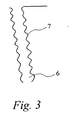
- Figure 3 shows a dividing wall having a roughened surface;
- Figure 4 is a simplified support;
- Figure 5 is the end view of the support of Figure 3 containing a separator;
- Figure 6 is an end view of a support for a single row print head having air insulation between the inlet and outlet manifolds;
- Figure 7 is an end view of a support containing a thermal bar;
- Figure 8 is a perspective view of a support according to a further embodiment of the invention;
- Figure 9 is a view similar to Figure 8 illustrating a modification; and
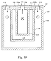
- Figure 10 is a sectional view of a support according to yet a further embodiment of the invention.
- Figure 1 depicts an ink supply support according to the prior art. The support is formed of extruded aluminium and consists of two
separate manifolds wall 6 dividing the two manifolds is thus formed of the same material as the exterior wall of the support. - Ink enters and leaves through ports (not shown) situated at one end of the support. The ink flows down the
inner manifold 2 in one direction as depicted by thesymbol 10 and flows back down the outer manifold in the opposite direction as depicted by thesymbol 12. - The inner and
outer manifolds print head 14 attached to the top of the support. Two arrays of piezoelectric material containing sawnparallel channels arrow 18 and returns to the outer manifold of the support after passing through the ejection channel as shown by thearrow 20. - In the ideal thermal situation, the ink should enter the support at a well-controlled temperature, pass along the inlet manifold at the same temperature, flow through the channels picking up heat from the PZT, and leave via the outlet manifolds at a uniform but higher temperature.
- In practice, when a channel is printing, the PZT dissipates considerable heat, some of which is removed with the ejected drops. When the channel is not printing, the PZT may be doing nothing. Constant temperature waveforms which are applied to the non ejecting channels and cause the PZT to dissipate that part of the heat generated during printing which is not removed by the ejected droplets are used to maintain the temperature within the channels at a constant temperature along the entire array.
- The chips also generate heat, the amount depending on the firing voltage and (to a lesser extent) on the image being printed. The chips require cooling and thus have been situated so that this heat finds its way into the
outlet manifold 4. - The aluminium chassis that forms the support provides a conduction path that attempts to equalise temperatures along the array. Ink flow along the array assists in the distribution of heat.
- Heat dissipated by the PZT is of the order of 0.015 W/channel, and the chips dissipate a similar amount. If all of this heat were to go into the ink through flow then the temperature rise of the ink in passing through the PWA would be 5.40C.
- The amount of heat removed during full black printing is 0.0015 W/channel, that is to say a small fraction of the total heat dissipation. When the printing is lighter than full black, the removal of heat by the drops is even less significant. Heat losses from the print head to the surroundings are modest and any covers protecting the electronics act to further reduce the heat loss.
- It has been found that the aluminium chassis has the disadvantageous feature of transferring a significant amount of heat from the outlet manifold to the inlet manifold as well as the advantageous feature of transferring heat along the length of the support. Taking a temperature difference of 5.40C, and a heat transfer coefficient of 1000 W/m2C, the heat transferred through two walls, each 30 mm high and running the length of the array, is 52 watts. Effectively, the print head is operating as a counter current heat exchanger, the aluminium chassis and the ink being unable to completely equalise the temperature difference along the array. Figure 2 is a graphical representation of the temperature difference along the print head support.
- In one aspect of the present invention, as depicted in Figures 3 to 6, the support is modified such that the heat transfer coefficient between the ink inlet manifold and the ink outlet manifold is less than that of the prior art.
- A number of methods have been found to be suitable. In a first embodiment as shown in Figure 3, the divider separating the two conduits is a wall that is roughened or shaped so as to provide a thick boundary or stagnant layer. Where corrugation is used, the
ridges 7 can extend either parallel to or perpendicular to the direction of fluid flow. In this case, where the support is extruded, the ridges extend parallel to the direction of fluid flow. Alternatively, an insulating coating can be applied to one or both sides of the dividing wall. - In these embodiments the divider can be formed from the same material as the extruded perimeter. It is of course possible to use other materials as the dividing wall as described in the alternative embodiments of the first embodiment and as depicted in Figures 4 to 7.
- It is known that the difference in the coefficient of thermal expansion between PZT and the aluminium causes problems during operation. In the prior art excess expansion of the aluminium is prevented through the provision of tie-rods and the like. Aluminium is used because it is cheap and it is easy to form an extruded component with the manifolds and dividing walls in place.
- In Figure 3, a ceramic support is used. Ceramics cannot be extruded to the same amount of complexity as aluminium, but simple structures are possible. The ceramic has a similar coefficient of thermal expansion to the piezoelectric actuator and thus inappropriate expansion differences are not present.
- The
inlet 9 andoutlet 11 manifolds for the print head are formed by etching, sawing or ablation. Because an insert will be attached to the inside of the support to provide the flow features, it is not necessary to manufacture the slots to as high a degree of tolerance as in the aluminium support. The features of the manifolds are provided by an insert that acts as an insulator between theinlet 2 and the outlet manifolds 4 as shown in Figure 5. - The
plastic inset 22 is adhesively attached to the upper surface of thesupply support 28. Spacers 24 are used to ensure there is no adverse movement of the spacer. In certain circumstances it is beneficial to provide baffles, ridges or a roughened surface to increase the boundary layer of ink around the dividing wall and to provide additional insulation. Alternatively, as the insert can be manufactured by moulding or casting, a double wall may be formed and which provides an insulating air cavity. - The plastic wall may be replaced by a closed-cell foam rubber wall, chosen to be resistant to chemical attack by the ink, capable of being formed into an appropriate shape and which does not shed dirt particles into the ink. Other materials are also possible without departing from the scope of the present invention.
- Figure 6 shows a single row print head formed on a support. The
piezoelectric material 16a provides a flow circuit between aninlet manifold 2 and anoutlet manifold 4. The manifolds are separated by a plastic material formed such that there is acavity 30 between them. - The cavity is filled with a fluid, preferably gaseous, or a vacuum in order to provide insulation between the two manifolds. The dividing wall is attached to the support at least one point and may be rigid or flexible. Where the wall is flexible, a source of pressurised fluid can be used to change the pressures within the manifolds. A 3mm gap of air reduces the difference along a 20cm array to below.
- A further method of improving the distribution of heat along the support, rather than across the walls is to provide a highly conductive heat transfer bar within one of the manifolds as depicted in Figure 7. The
bar 36 can extend beyond the edge of the support and attached to an external heat exchanger, or alternatively it may be contained fully within the support. In this embodiment of the present invention the heat transfer along the array is increased to the point where the transfer across the divider separating the inlet and outlet manifolds becomes insignificant. - Figure 8 depicts a further design of manifold that is preferably formed of a moulded material, the manifold component having an
inlet 2 and two outlet manifolds 4. As the manifolds are moulded it is possible to mould a double wall dividing the inlet and outlet manifolds. The double wall comprises a cavity of air that acts as an insulator reducing the amount of heat transfer across the wall. - One of the purposes of the manifold component is to receive the heat from the driver chips bonded to its outer surfaces. Where the plastics material of the component has a low thermal conductivity this heat transfer is reduced. A metallic, or other higher thermally
conductive material 40 may be moulded into the component during manufacture as shown in Figure 9. This allows heat transfer between the chip and the outlet manifold whilst still providing insulation to the inner manifold. - An alternative to this is to mould the majority of the manifold component in a material having a relatively high thermal conductivity and to mould the walls dividing the inlet and outlet manifolds in a material of low thermal conductivity.
- In the structure shown in Figure 10, a hollow,
cylindrical support 100 serves to mount a plurality of ink jet print heads 102. Thesupport 100 has aexternal wall section 110, folded into a U-shape. The support provides a mountingsurface 112 on which are supported the print heads, each of which comprises a layer of piezoelectric material 104 defining ink channels extending across the support and acover plate 106 definingnozzles 108. - In the section shown in Figure 10, two ink channels are defined by
respective sections inlet port 122 in the mounting surface flows continuously in opposing transverse directions through the two ink channels to be collected byrespective outlet ports 114. - The
outlet ports 114 communicate with an outlet ink manifold defined by theexternal wall section 110. - An internal wall section takes the form of
double walls cavity 120. This cavity may contain air at atmospheric material, be evacuated or contain trapped ink or other appropriate liquid. The cavity may be filled with foam or other cellular material. - The inlet ink manifold defined by the cavity wall 116,118 communicates with the
ink inlet port 122. - The structure shown in Figure 10, may be formed in one piece by - for example - extrusion or moulding or by a range of other forming techniques. In one example, the structure is formed of extruded aluminium or other suitable metal. In another example the structure is formed of moulded plastic. Optionally, in this example, an additional wall section is provided of metal or metal loaded plastic to promote heat transfer along the length of the support. In other examples, the structure is formed from wall sections of different material.
- In one example, a port plate (not shown) is interposed between the wall sections and the print heads to assist in defining the ink inlet and outlet ports. In this arrangement, openings defined with relatively low precision by the cooperating wall sections, communicate with more precisely defined port openings in the interposed plate. According to the manufacturing process, this port plate may form part of the support or part of the print head.
Claims (24)
- A support for an of inkjet print head demanding in use a continuous flow of ink, said support providing a mounting surface which is arranged to receive at least one print head and which provides ink inlet and outlet ports for communication with the print head or heads, the support comprising at least two wall sections cooperating to define inlet and outlet ink manifolds, one wall section being thermally conducting so as to promote heat transfer along the length of the support, another wall section being provided with insulating means, said insulating means inhibiting heat transfer between the inlet and outlet manifolds.
- A support according to Claim 1 wherein said insulating means comprises a portion of material adjacent to said another wall section having a lower coefficient of thermal conduction than said wall.
- A support according to Claim 2, wherein said portion of material is a fluid.
- A support according to any one of Claims 1 to 3, wherein said insulating means comprises an air gap.
- A support according to any one of the preceding claims, wherein said insulating means comprises a double wall arrangement.
- A support according to Claim 5, wherein said double wall arrangement defines a cavity containing a gas or a liquid.
- A support according to Claim 5, wherein said double wall arrangement defines a vacuum cavity.
- A support according to any one of the preceding claims, wherein said insulating means comprises an area of roughening or shaping of said another wall section so as to provide a boundary or stagnant layer of fluid adjacent to said another wall section.
- A support according to Claim 8, wherein said roughening or shaping comprises the provision of ridges on said another wall section, said ridges extending parallel to the direction of fluid flow.
- A support according to Claim 9 wherein said fluid is ink.
- A support according to any one of the preceding claims, wherein the thermally conducting wall section is formed from metal.
- A support according to any one of the preceding claims, wherein the wall sections are folded.
- A support according to any one of the preceding claims, wherein at least one of the wall sections is U-shaped in the cross section of the support.
- A support according to any one of the preceding claims, wherein in the cross section of the support, one ink manifold substantially surrounds the other.
- A support according to any one of the preceding claims, further comprising a heat sink disposed within one of said manifolds.
- A support according to Claim 15, wherein said heat sink extends substantially the entire length of said one of said manifolds.
- A support for an inkjet print head demanding in use a continuous flow of ink, said support providing a mounting surface which is arranged to receive at least one print head and which provides ink inlet and outlet ports for communication with the print head or heads, the support comprising at least two wall sections cooperating to define inlet and outlet ink manifolds, one wall section being formed of a thermally conducting material so as to promote heat transfer along the length of the support, another wall section being formed of a different material being thermally insulating so as to inhibit heat transfer between the inlet and outlet manifolds.
- A support according to Claim 17, wherein the thermally conducting wall section is formed from metal.
- A support according to Claim 17, wherein the thermally conducting wall section is formed from a ceramic.
- A support according to any one of claims 17 to 19, wherein the thermally insulating wall section is formed of cellular material.
- A support according to any one of claims 17 to 20, wherein said thermally insulating wall section is formed of plastics material.
- A support according to any one of the Claims 18 to 21, wherein in the cross section of the support, one ink manifold substantially surrounds the other.
- Apparatus comprising a support according to any preceding claim and an ink jet print head comprising at least one fluid chamber, said inlet manifold and said outlet manifold being fluidically connected through said at least one fluid chamber.
- Apparatus according to Claim 23, wherein said at least one fluid chamber is an ejection chamber having an ejection nozzle.
Applications Claiming Priority (3)
| Application Number | Priority Date | Filing Date | Title |
|---|---|---|---|
| GBGB0121619.1A GB0121619D0 (en) | 2001-09-07 | 2001-09-07 | Droplet depostion apparatus |
| GB0121619 | 2001-09-07 | ||
| PCT/GB2002/004078 WO2003022587A1 (en) | 2001-09-07 | 2002-09-09 | Droplet deposition apparatus |
Publications (2)
| Publication Number | Publication Date |
|---|---|
| EP1423283A1 EP1423283A1 (en) | 2004-06-02 |
| EP1423283B1 true EP1423283B1 (en) | 2007-11-14 |
Family
ID=9921647
Family Applications (1)
| Application Number | Title | Priority Date | Filing Date |
|---|---|---|---|
| EP02758571A Expired - Lifetime EP1423283B1 (en) | 2001-09-07 | 2002-09-09 | Droplet deposition apparatus |
Country Status (13)
| Country | Link |
|---|---|
| US (1) | US7204578B2 (en) |
| EP (1) | EP1423283B1 (en) |
| JP (1) | JP4382481B2 (en) |
| KR (1) | KR20040048406A (en) |
| CN (1) | CN1294021C (en) |
| AT (1) | ATE378182T1 (en) |
| AU (1) | AU2002324153B2 (en) |
| BR (1) | BR0205974A (en) |
| DE (1) | DE60223558T2 (en) |
| ES (1) | ES2295392T3 (en) |
| GB (1) | GB0121619D0 (en) |
| IL (2) | IL160671A0 (en) |
| WO (1) | WO2003022587A1 (en) |
Families Citing this family (9)
| Publication number | Priority date | Publication date | Assignee | Title |
|---|---|---|---|---|
| EP1204533B1 (en) * | 1999-06-30 | 2005-04-06 | Silverbrook Research Pty. Limited | Printhead support structure and assembly |
| US6755509B2 (en) * | 2002-11-23 | 2004-06-29 | Silverbrook Research Pty Ltd | Thermal ink jet printhead with suspended beam heater |
| GB0606685D0 (en) † | 2006-04-03 | 2006-05-10 | Xaar Technology Ltd | Droplet Deposition Apparatus |
| JP4999663B2 (en) * | 2007-12-03 | 2012-08-15 | キヤノン株式会社 | Inkjet recording head |
| US8042927B2 (en) | 2008-09-30 | 2011-10-25 | Xerox Corporation | Melt reservoir housing |
| JP5665363B2 (en) * | 2010-05-14 | 2015-02-04 | キヤノン株式会社 | Liquid discharge head |
| JP2012125936A (en) * | 2010-12-13 | 2012-07-05 | Toshiba Tec Corp | Inkjet head |
| CN103386815B (en) * | 2013-07-04 | 2015-10-28 | 宁波源丰消防设备有限公司 | A kind of coating printing device |
| GB2546097B (en) | 2016-01-08 | 2020-12-30 | Xaar Technology Ltd | Droplet deposition head |
Family Cites Families (8)
| Publication number | Priority date | Publication date | Assignee | Title |
|---|---|---|---|---|
| US4887100A (en) | 1987-01-10 | 1989-12-12 | Am International, Inc. | Droplet deposition apparatus |
| JP3114776B2 (en) * | 1992-06-23 | 2000-12-04 | セイコーエプソン株式会社 | Printer using inkjet line recording head |
| JP2870459B2 (en) | 1995-10-09 | 1999-03-17 | 日本電気株式会社 | INK JET RECORDING APPARATUS AND MANUFACTURING METHOD THEREOF |
| WO2000024584A1 (en) | 1998-10-24 | 2000-05-04 | Xaar Technology Limited | Droplet deposition apparatus |
| AU762936B2 (en) | 1998-11-14 | 2003-07-10 | Xaar Technology Limited | Droplet deposition apparatus |
| US6428145B1 (en) * | 1998-12-17 | 2002-08-06 | Hewlett-Packard Company | Wide-array inkjet printhead assembly with internal electrical routing system |
| GB9828476D0 (en) * | 1998-12-24 | 1999-02-17 | Xaar Technology Ltd | Apparatus for depositing droplets of fluid |
| AUPQ605900A0 (en) * | 2000-03-06 | 2000-03-30 | Silverbrook Research Pty Ltd | Thermal expansion compensation for printhead assemblies |
-
2001
- 2001-09-07 GB GBGB0121619.1A patent/GB0121619D0/en not_active Ceased
-
2002
- 2002-09-09 ES ES02758571T patent/ES2295392T3/en not_active Expired - Lifetime
- 2002-09-09 CN CNB028172914A patent/CN1294021C/en not_active Expired - Fee Related
- 2002-09-09 DE DE60223558T patent/DE60223558T2/en not_active Expired - Lifetime
- 2002-09-09 AU AU2002324153A patent/AU2002324153B2/en not_active Ceased
- 2002-09-09 US US10/488,620 patent/US7204578B2/en not_active Expired - Lifetime
- 2002-09-09 JP JP2003526691A patent/JP4382481B2/en not_active Expired - Fee Related
- 2002-09-09 EP EP02758571A patent/EP1423283B1/en not_active Expired - Lifetime
- 2002-09-09 WO PCT/GB2002/004078 patent/WO2003022587A1/en active IP Right Grant
- 2002-09-09 IL IL16067102A patent/IL160671A0/en active IP Right Grant
- 2002-09-09 AT AT02758571T patent/ATE378182T1/en not_active IP Right Cessation
- 2002-09-09 BR BR0205974-6A patent/BR0205974A/en active Search and Examination
- 2002-09-09 KR KR10-2004-7003394A patent/KR20040048406A/en not_active Application Discontinuation
-
2004
- 2004-03-01 IL IL160671A patent/IL160671A/en not_active IP Right Cessation
Also Published As
| Publication number | Publication date |
|---|---|
| WO2003022587A1 (en) | 2003-03-20 |
| AU2002324153B2 (en) | 2007-10-04 |
| BR0205974A (en) | 2003-09-30 |
| JP2005502499A (en) | 2005-01-27 |
| CN1294021C (en) | 2007-01-10 |
| DE60223558T2 (en) | 2008-10-23 |
| IL160671A (en) | 2007-10-31 |
| ES2295392T3 (en) | 2008-04-16 |
| EP1423283A1 (en) | 2004-06-02 |
| US20050134651A1 (en) | 2005-06-23 |
| GB0121619D0 (en) | 2001-10-31 |
| ATE378182T1 (en) | 2007-11-15 |
| CN1551835A (en) | 2004-12-01 |
| US7204578B2 (en) | 2007-04-17 |
| IL160671A0 (en) | 2004-08-31 |
| DE60223558D1 (en) | 2007-12-27 |
| KR20040048406A (en) | 2004-06-09 |
| JP4382481B2 (en) | 2009-12-16 |
Similar Documents
| Publication | Publication Date | Title |
|---|---|---|
| EP1255649B1 (en) | Droplet deposition apparatus | |
| KR100771090B1 (en) | Droplet deposition apparatus | |
| AU2001233870A1 (en) | Droplet deposition apparatus | |
| EP1423283B1 (en) | Droplet deposition apparatus | |
| JP6512886B2 (en) | Liquid discharge head | |
| JP5665363B2 (en) | Liquid discharge head | |
| AU2002324153A1 (en) | Droplet deposition apparatus | |
| US9457570B2 (en) | Liquid ejection head | |
| GB2522563A (en) | Droplet deposition apparatus and method for manufacturing the same | |
| AU762871B2 (en) | Droplet deposition apparatus | |
| JP4831305B2 (en) | Inkjet head | |
| EP3535131B1 (en) | Fluid flow structure | |
| JP2011235481A (en) | Liquid ejection apparatus | |
| EP4303010A1 (en) | Inkjet print head with continuous flow and improved temperature uniformity | |
| JPH03187753A (en) | Recorder | |
| WO2018236370A1 (en) | Dehumidifier condensing unit for an inkjet printer | |
| JP2005178240A (en) | Inkjet printer | |
| JP2001030495A (en) | Long ink jet head |
Legal Events
| Date | Code | Title | Description |
|---|---|---|---|
| PUAI | Public reference made under article 153(3) epc to a published international application that has entered the european phase |
Free format text: ORIGINAL CODE: 0009012 |
|
| 17P | Request for examination filed |
Effective date: 20040227 |
|
| AK | Designated contracting states |
Kind code of ref document: A1 Designated state(s): AT BE BG CH CY CZ DE DK EE ES FI FR GB GR IE IT LI LU MC NL PT SE SK TR |
|
| AX | Request for extension of the european patent |
Extension state: AL LT LV MK RO SI |
|
| 17Q | First examination report despatched |
Effective date: 20041217 |
|
| GRAP | Despatch of communication of intention to grant a patent |
Free format text: ORIGINAL CODE: EPIDOSNIGR1 |
|
| GRAS | Grant fee paid |
Free format text: ORIGINAL CODE: EPIDOSNIGR3 |
|
| GRAA | (expected) grant |
Free format text: ORIGINAL CODE: 0009210 |
|
| AK | Designated contracting states |
Kind code of ref document: B1 Designated state(s): AT BE BG CH CY CZ DE DK EE ES FI FR GB GR IE IT LI LU MC NL PT SE SK TR |
|
| REG | Reference to a national code |
Ref country code: GB Ref legal event code: FG4D |
|
| REG | Reference to a national code |
Ref country code: CH Ref legal event code: EP |
|
| REG | Reference to a national code |
Ref country code: IE Ref legal event code: FG4D |
|
| REF | Corresponds to: |
Ref document number: 60223558 Country of ref document: DE Date of ref document: 20071227 Kind code of ref document: P |
|
| REG | Reference to a national code |
Ref country code: ES Ref legal event code: FG2A Ref document number: 2295392 Country of ref document: ES Kind code of ref document: T3 |
|
| PG25 | Lapsed in a contracting state [announced via postgrant information from national office to epo] |
Ref country code: SE Free format text: LAPSE BECAUSE OF FAILURE TO SUBMIT A TRANSLATION OF THE DESCRIPTION OR TO PAY THE FEE WITHIN THE PRESCRIBED TIME-LIMIT Effective date: 20080214 Ref country code: LI Free format text: LAPSE BECAUSE OF FAILURE TO SUBMIT A TRANSLATION OF THE DESCRIPTION OR TO PAY THE FEE WITHIN THE PRESCRIBED TIME-LIMIT Effective date: 20071114 Ref country code: CH Free format text: LAPSE BECAUSE OF FAILURE TO SUBMIT A TRANSLATION OF THE DESCRIPTION OR TO PAY THE FEE WITHIN THE PRESCRIBED TIME-LIMIT Effective date: 20071114 |
|
| PG25 | Lapsed in a contracting state [announced via postgrant information from national office to epo] |
Ref country code: BG Free format text: LAPSE BECAUSE OF FAILURE TO SUBMIT A TRANSLATION OF THE DESCRIPTION OR TO PAY THE FEE WITHIN THE PRESCRIBED TIME-LIMIT Effective date: 20080214 Ref country code: FI Free format text: LAPSE BECAUSE OF FAILURE TO SUBMIT A TRANSLATION OF THE DESCRIPTION OR TO PAY THE FEE WITHIN THE PRESCRIBED TIME-LIMIT Effective date: 20071114 |
|
| REG | Reference to a national code |
Ref country code: CH Ref legal event code: PL |
|
| PG25 | Lapsed in a contracting state [announced via postgrant information from national office to epo] |
Ref country code: AT Free format text: LAPSE BECAUSE OF FAILURE TO SUBMIT A TRANSLATION OF THE DESCRIPTION OR TO PAY THE FEE WITHIN THE PRESCRIBED TIME-LIMIT Effective date: 20071114 |
|
| PG25 | Lapsed in a contracting state [announced via postgrant information from national office to epo] |
Ref country code: CZ Free format text: LAPSE BECAUSE OF FAILURE TO SUBMIT A TRANSLATION OF THE DESCRIPTION OR TO PAY THE FEE WITHIN THE PRESCRIBED TIME-LIMIT Effective date: 20071114 Ref country code: DK Free format text: LAPSE BECAUSE OF FAILURE TO SUBMIT A TRANSLATION OF THE DESCRIPTION OR TO PAY THE FEE WITHIN THE PRESCRIBED TIME-LIMIT Effective date: 20071114 |
|
| ET | Fr: translation filed | ||
| PG25 | Lapsed in a contracting state [announced via postgrant information from national office to epo] |
Ref country code: BE Free format text: LAPSE BECAUSE OF FAILURE TO SUBMIT A TRANSLATION OF THE DESCRIPTION OR TO PAY THE FEE WITHIN THE PRESCRIBED TIME-LIMIT Effective date: 20071114 Ref country code: SK Free format text: LAPSE BECAUSE OF FAILURE TO SUBMIT A TRANSLATION OF THE DESCRIPTION OR TO PAY THE FEE WITHIN THE PRESCRIBED TIME-LIMIT Effective date: 20071114 |
|
| PLBE | No opposition filed within time limit |
Free format text: ORIGINAL CODE: 0009261 |
|
| STAA | Information on the status of an ep patent application or granted ep patent |
Free format text: STATUS: NO OPPOSITION FILED WITHIN TIME LIMIT |
|
| PG25 | Lapsed in a contracting state [announced via postgrant information from national office to epo] |
Ref country code: PT Free format text: LAPSE BECAUSE OF FAILURE TO SUBMIT A TRANSLATION OF THE DESCRIPTION OR TO PAY THE FEE WITHIN THE PRESCRIBED TIME-LIMIT Effective date: 20080414 |
|
| 26N | No opposition filed |
Effective date: 20080815 |
|
| PGFP | Annual fee paid to national office [announced via postgrant information from national office to epo] |
Ref country code: IE Payment date: 20080917 Year of fee payment: 7 Ref country code: NL Payment date: 20080903 Year of fee payment: 7 |
|
| PG25 | Lapsed in a contracting state [announced via postgrant information from national office to epo] |
Ref country code: GR Free format text: LAPSE BECAUSE OF FAILURE TO SUBMIT A TRANSLATION OF THE DESCRIPTION OR TO PAY THE FEE WITHIN THE PRESCRIBED TIME-LIMIT Effective date: 20080215 |
|
| PGFP | Annual fee paid to national office [announced via postgrant information from national office to epo] |
Ref country code: ES Payment date: 20081021 Year of fee payment: 7 |
|
| PGFP | Annual fee paid to national office [announced via postgrant information from national office to epo] |
Ref country code: IT Payment date: 20080927 Year of fee payment: 7 |
|
| PG25 | Lapsed in a contracting state [announced via postgrant information from national office to epo] |
Ref country code: MC Free format text: LAPSE BECAUSE OF NON-PAYMENT OF DUE FEES Effective date: 20080930 Ref country code: EE Free format text: LAPSE BECAUSE OF FAILURE TO SUBMIT A TRANSLATION OF THE DESCRIPTION OR TO PAY THE FEE WITHIN THE PRESCRIBED TIME-LIMIT Effective date: 20071114 |
|
| PG25 | Lapsed in a contracting state [announced via postgrant information from national office to epo] |
Ref country code: CY Free format text: LAPSE BECAUSE OF FAILURE TO SUBMIT A TRANSLATION OF THE DESCRIPTION OR TO PAY THE FEE WITHIN THE PRESCRIBED TIME-LIMIT Effective date: 20071114 |
|
| REG | Reference to a national code |
Ref country code: NL Ref legal event code: V1 Effective date: 20100401 |
|
| PG25 | Lapsed in a contracting state [announced via postgrant information from national office to epo] |
Ref country code: NL Free format text: LAPSE BECAUSE OF NON-PAYMENT OF DUE FEES Effective date: 20100401 Ref country code: LU Free format text: LAPSE BECAUSE OF NON-PAYMENT OF DUE FEES Effective date: 20080909 Ref country code: IE Free format text: LAPSE BECAUSE OF NON-PAYMENT OF DUE FEES Effective date: 20090909 |
|
| PG25 | Lapsed in a contracting state [announced via postgrant information from national office to epo] |
Ref country code: TR Free format text: LAPSE BECAUSE OF FAILURE TO SUBMIT A TRANSLATION OF THE DESCRIPTION OR TO PAY THE FEE WITHIN THE PRESCRIBED TIME-LIMIT Effective date: 20071114 |
|
| PG25 | Lapsed in a contracting state [announced via postgrant information from national office to epo] |
Ref country code: IT Free format text: LAPSE BECAUSE OF NON-PAYMENT OF DUE FEES Effective date: 20090909 |
|
| REG | Reference to a national code |
Ref country code: ES Ref legal event code: FD2A Effective date: 20110712 |
|
| PG25 | Lapsed in a contracting state [announced via postgrant information from national office to epo] |
Ref country code: ES Free format text: LAPSE BECAUSE OF NON-PAYMENT OF DUE FEES Effective date: 20110630 |
|
| PG25 | Lapsed in a contracting state [announced via postgrant information from national office to epo] |
Ref country code: ES Free format text: LAPSE BECAUSE OF NON-PAYMENT OF DUE FEES Effective date: 20090910 |
|
| PGFP | Annual fee paid to national office [announced via postgrant information from national office to epo] |
Ref country code: DE Payment date: 20140903 Year of fee payment: 13 |
|
| PGFP | Annual fee paid to national office [announced via postgrant information from national office to epo] |
Ref country code: GB Payment date: 20140903 Year of fee payment: 13 |
|
| PGFP | Annual fee paid to national office [announced via postgrant information from national office to epo] |
Ref country code: FR Payment date: 20140906 Year of fee payment: 13 |
|
| REG | Reference to a national code |
Ref country code: DE Ref legal event code: R119 Ref document number: 60223558 Country of ref document: DE |
|
| GBPC | Gb: european patent ceased through non-payment of renewal fee |
Effective date: 20150909 |
|
| REG | Reference to a national code |
Ref country code: FR Ref legal event code: ST Effective date: 20160531 |
|
| PG25 | Lapsed in a contracting state [announced via postgrant information from national office to epo] |
Ref country code: DE Free format text: LAPSE BECAUSE OF NON-PAYMENT OF DUE FEES Effective date: 20160401 Ref country code: GB Free format text: LAPSE BECAUSE OF NON-PAYMENT OF DUE FEES Effective date: 20150909 |
|
| PG25 | Lapsed in a contracting state [announced via postgrant information from national office to epo] |
Ref country code: FR Free format text: LAPSE BECAUSE OF NON-PAYMENT OF DUE FEES Effective date: 20150930 |