EP1422807A2 - Reciprocating rotary permanent magnet motor - Google Patents
Reciprocating rotary permanent magnet motor Download PDFInfo
- Publication number
- EP1422807A2 EP1422807A2 EP03026121A EP03026121A EP1422807A2 EP 1422807 A2 EP1422807 A2 EP 1422807A2 EP 03026121 A EP03026121 A EP 03026121A EP 03026121 A EP03026121 A EP 03026121A EP 1422807 A2 EP1422807 A2 EP 1422807A2
- Authority
- EP
- European Patent Office
- Prior art keywords
- rotor
- permanent magnets
- polar axes
- pole parts
- rotary solenoid
- Prior art date
- Legal status (The legal status is an assumption and is not a legal conclusion. Google has not performed a legal analysis and makes no representation as to the accuracy of the status listed.)
- Withdrawn
Links
Images



Classifications
-
- H—ELECTRICITY
- H02—GENERATION; CONVERSION OR DISTRIBUTION OF ELECTRIC POWER
- H02K—DYNAMO-ELECTRIC MACHINES
- H02K26/00—Machines adapted to function as torque motors, i.e. to exert a torque when stalled
-
- H—ELECTRICITY
- H02—GENERATION; CONVERSION OR DISTRIBUTION OF ELECTRIC POWER
- H02K—DYNAMO-ELECTRIC MACHINES
- H02K1/00—Details of the magnetic circuit
- H02K1/06—Details of the magnetic circuit characterised by the shape, form or construction
- H02K1/22—Rotating parts of the magnetic circuit
- H02K1/27—Rotor cores with permanent magnets
- H02K1/2706—Inner rotors
- H02K1/272—Inner rotors the magnetisation axis of the magnets being perpendicular to the rotor axis
- H02K1/274—Inner rotors the magnetisation axis of the magnets being perpendicular to the rotor axis the rotor consisting of two or more circumferentially positioned magnets
-
- H—ELECTRICITY
- H02—GENERATION; CONVERSION OR DISTRIBUTION OF ELECTRIC POWER
- H02K—DYNAMO-ELECTRIC MACHINES
- H02K2201/00—Specific aspects not provided for in the other groups of this subclass relating to the magnetic circuits
- H02K2201/06—Magnetic cores, or permanent magnets characterised by their skew
Definitions
- the present invention relates to rotary solenoids in which the rotor undergoes reciprocating motion within a specific rotational range due to interaction between permanent magnets on a rotor and induction coils on a stator.
- FIGS. 6-8 illustrate the structure and operation of a conventional rotary solenoid.
- the rotary solenoid is equipped with the following: a stator 1, which has a pair of opposed pole parts 2 that face each other and extend inwardly; induction coils 3, which are wrapped around the pole parts 2, respectively; and a rotor 5, which is fixed to a pair of permanent magnets 4 that face the pole parts 2, respectively.
- the magnets 4 are located within the stator 1, as shown.
- the permanent magnets 4 receive a repulsive force from the facing pole parts 2, and rotate in the direction shown by arrow A in FIG. 7.
- the rotor 5, as shown in FIG. 8, rotates until it strikes a stopper (not shown) where it stops.
- the stopper is located at a stopping point (approximately 76° from the rotor position of Fig. 6) from which the rotor 5 can return by itself.
- a stopping point approximately 76° from the rotor position of Fig. 6
- FIG. 9 is a graph showing the torque characteristics of the rotary solenoid of Figs. 6-8.
- FIG. 9 is a graph showing the torque characteristics of the rotary solenoid of Figs. 6-8.
- the conventional rotary solenoid of Figs. 6-8 there is essentially no torque in the range of rotor rotation between 0° and 30°, as shown in Fig. 9, where 0° is the rotor position shown in Fig. 6, at which the permanent magnets 4 are directly in alignment with the respective pole parts 2.
- An object of the invention is to provide a rotary solenoid that is able to increase the angular range and the torque while reducing power consumption.
- the invention is a rotary solenoid including a rotor, which has a center axis. At least two permanent magnets are located on the rotor, and polar axes of the permanent magnets are positioned about the center axis at predetermined angular locations.
- a stator is located about the rotor. The stator includes pole parts, the number of which matches the number of permanent magnets.
- a coil is wrapped about each pole part. Polar axes of the pole parts are positioned about the center axis at predetermined angular locations.
- the rotor is driven in a predetermined angular range by magnetic fields induced by induction currents in the coils and by magnetic fields of the permanent magnets.
- the angular locations of the permanent magnets and the angular locations of the pole parts are mismatched such that there is no position of the rotor at which the polar axes of the permanent magnets are radially aligned with the polar axes of the pole parts.
- the stator includes at least two pairs of pole parts and the rotor includes at least two pairs of permanent magnets.
- the polar axes of the pole parts are uniformly distributed about the axis of the rotor, and the polar axes of the permanent magnets are non-uniformly distributed about the axis of the rotor.
- the polar axes of the pole parts are separated from one another by equal angular intervals, and the polar axes of the permanent magnets are separated from one another by unequal angular intervals.
- the distribution of the permanent magnets on the rotor is imbalanced.
- the invention is basically a rotary solenoid including a rotor, which has a center axis.
- the rotor includes at least two permanent magnetic polar axes at predetermined angular locations.
- a stator is located about the rotor, and the stator includes electromagnetic poles, each of which has a polar axes.
- the number of the electromagnetic poles on the stator matches the number of permanent magnetic polar axes on the rotor.
- the polar axes of the electromagnetic poles are positioned about the axis of the rotor at predetermined angular locations, and the rotor is driven in a predetermined angular range by magnetic fields created by the electromagnetic poles and by permanent magnetic fields of the rotor.
- the angular locations of the permanent magnetic polar axes and the angular locations of the polar axes of the electromagnetic poles are mismatched such that there is no position of the rotor at which the permanent magnetic polar axes of the rotor are radially aligned with the polar axes of the electromagnetic poles.
- This construction improves the performance characteristics of the rotary solenoid, as discussed in more detail below.
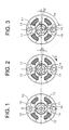
- FIGS. 1-3 are cross sectional diagrams showing the basic structure and operation of a rotary solenoid according to a first embodiment of the present invention
- FIG. 4 is a graph showing the angle-torque characteristics of a rotary solenoid according to the embodiment of Fig. 1;
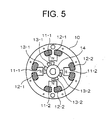
- FIG. 5 is a cross sectional diagram showing another embodiment of the present invention.
- FIGS. 6, 7 and 8 are cross sectional diagrams showing the basic structure and operation of a conventional rotary solenoid
- FIG. 9 is a graph showing the angle-torque characteristics of a conventional rotary solenoid
- a rotary solenoid has a stator 10 that has a pair of pole parts 11 facing in opposite directions and extending towards the central axis. Induction coils 12 are wrapped upon the pair of pole parts 11, and a rotor 14 is located on the inside of the stator 10. Each pole part 11 has a polar axis that is radial and perpendicular to the axis of the rotor 14. The pole parts 11 are symmetrical about a plane that includes the central axis, as shown. In other words, the pole parts are uniformly arranged about the axis of the rotor 14.
- the magnets 13 essentially face the pole parts 11.
- the permanent magnets 13 are magnetized in the direction of their thickness such that their polar axes are radial and perpendicular to the axis of the rotor.
- the permanent magnets 13 are not uniformly arranged about the axis of the rotor. In other words, at least one of the permanent magnets 13 is shifted in an angular direction such that the permanent magnets 13 cannot both be radially aligned with the corresponding pole parts 11, as shown in Fig. 1-3. That is, the angular spacing between the magnets 13 is non uniform, and at least one of the magnets 13 is angularly offset from, or radially misaligned with, the corresponding pole part 11.
- the center, or polar axis, of at least one of the permanent magnets 13 is radially misaligned with the center, or polar axis, of the corresponding pole part 11.
- a direct current excitation current is applied to the inductance coils 12 to cause each pole part 11 to have the same polarity as the corresponding permanent magnet 13.
- the excitation current is cut off when the rotor 14 has stopped at the stopping position.
- the rotor 14 engages a physical stopper, or abutment (not shown), at the stopping position.
- the stopping point is a point from which the rotor 14 can return automatically when the excitation current is cut off.
- the rotor 14 undergoes reciprocating motion within a specific angular range according to the attractive forces and repulsive forces that are generated between the pole parts 11 and the permanent magnets 13 due to the supply and termination of the DC excitation current to the inductance coils 12.
- the permanent magnets 13 will receive a repulsive force from the corresponding pole parts 11, and will rotate in the direction of arrow A in FIG.2.
- the rotor 14, as shown in FIG. 3, will stop after it has rotated to the stopping point (which is approximately 76° from the rotor position of Fig. 1). If the DC excitation current is stopped when the rotor 14 is in the state of Fig. 3, the magnetic force of the pole parts 11 will be removed, and the permanent magnets 13 of the rotor 14 will again be attracted to the pole parts 11, and the rotor 14 will return to the position shown in FIG. 1.
- FIG. 4 is a graph showing the relationship between the angle of rotation of the rotary solenoid and the torque characteristics of the embodiment shown in Figs. 1-3.
- significant torque is produced in the range of rotor rotation between 0° and 20°, where 0° is the equilibrium rotor position illustrated in Fig. 1.
- the generation of a repulsive torque is eliminated, and this improves the characteristics of the rotary solenoid (its range of rotation, angular velocity, and torque stability).
- the pole parts 11, which are located on the stator 10 are symmetrical about a plane that includes the center axis, and at least one of the permanent magnets 13 on the rotor 14 is angularly shifted toward the other permanent magnet 13.
- the angle between the rotor position of Fig. 1 and the starting point is relatively small.
- FIG. 5 is a diagram showing the basic structure of a rotary solenoid according to another embodiment of the present invention.
- the rotary solenoid has a pair of permanent magnets 13 and a pair of pole parts 11.
- the rotary solenoid can have additional permanent magnets and an equal number of pole parts, as shown in Fig. 5.
- two pairs of permanent magnets 13-1, 13-2 and two pairs of pole parts 11-1, 11-2 are provided, but the numbers of pole parts and permanent magnets are not so limited.
- the pole parts 11-1, 11-2 each have a polar axis that is radial and perpendicular to the axis of the rotor 14.
- the pole parts are spaced apart with uniform angular intervals, as shown. In other words, the pole parts 11-1 and 11-2 are symmetrically arranged.
- the permanent magnets 13-1 are magnetized in the direction of their thickness such that the polar axes of the magnets 13-1 are radial and perpendicular to the axis of the rotor 14. At least one magnet 13-1 of the first pair is shifted angularly from a position in direct radial alignment with a corresponding one of the pole parts 11-1. In other words, the magnets 13-1 are angularly offset from the corresponding pole parts 11-1, as shown. Furthermore the permanent magnets 13-2 of the second pair are magnetized in the direction of their thickness such that the polar axes of the permanent magnets are radial and perpendicular to the axis of the rotor 14.
- At least one of the magnets 13-2 of the second pair is shifted angularly from a position in direct radial alignment with a corresponding one of the pole parts 11-2. Therefore, there is radial misalignment between the permanent magnets 13-1, 13-2 and the corresponding pole parts 11-1, 11-2.
- the center, or polar axis, of at least one of the permanent magnets 13-1, 13-2 of each pair is radially misaligned with the center, or polar axis, of the corresponding pole part 11-1, 11-2.
- the operation of the rotary solenoid of Fig. 5 is the same as that of the rotary solenoid of Figs. 1-3 except that there are additional poles.
- the permanent magnets 13 of the rotor 14 are angularly shifted from positions in direct radial alignment with the corresponding pole parts 11, but the present invention is not so limited.
- the permanent magnets 13 can be located at uniform angular intervals, and the pole parts 11 of the stator 10 may be angularly shifted from positions of direct radial alignment with the permanent magnets 13 to obtain the same results. This is true for rotary solenoids having multiple permanent magnets and multiple pole parts as well.
- permanent magnets were used; however, magnetized portions of the rotor can be used instead. In other words, a position of magnetization on the rotor can be shifted to achieve the same result as shifting the position of a permanent magnet.
Landscapes
- Engineering & Computer Science (AREA)
- Power Engineering (AREA)
- Electromagnets (AREA)
- Reciprocating, Oscillating Or Vibrating Motors (AREA)
Abstract
Description
Claims (10)
- A rotary solenoid comprising:a rotor, which has a center axis, wherein at least two permanent magnets are located on the rotor, and polar axes of the permanent magnets are positioned about the center axis at predetermined angular locations;a stator that is located about the rotor, wherein the stator includes pole parts, the number of which matches the number of permanent magnets, and a coil is wrapped about each pole part, wherein polar axes of the pole parts are positioned about the center axis at predetermined angular locations, and the rotor is driven in a predetermined angular range by magnetic fields induced by induction currents in the coils and by magnetic fields of the permanent magnets, wherein the angular locations of the permanent magnets and the angular locations of the pole parts are mismatched such that there is no position of the rotor at which the polar axes of the permanent magnets are radially aligned with the polar axes of the pole parts.
- A rotary solenoid according to claim 1, wherein the stator includes at least two pairs of pole parts and the rotor includes at least two pairs of permanent magnets.
- A rotary solenoid according to claim 1, wherein the polar axes of the pole parts are uniformly distributed about the axis of the rotor, and the polar axes of the permanent magnets are non-uniformly distributed about the axis of the rotor.
- A rotary solenoid according to claim 1, wherein the polar axes of the pole parts are separated from one another by equal angular intervals, and the polar axes of the permanent magnets are separated from one another by unequal angular intervals.
- A rotary solenoid according to claim 1, wherein the distribution of the permanent magnets on the rotor is imbalanced.
- A rotary solenoid comprising:a rotor, which has a center axis, wherein the rotor includes at least two permanent magnetic polar axes at predetermined angular locations;a stator that is located about the rotor, wherein the stator includes electromagnetic poles, each of which has a polar axes, and the number of the electromagnetic poles on the stator matches the number of permanent magnetic polar axes on the rotor, wherein the polar axes of the electromagnetic poles are positioned about the axis of the rotor at predetermined angular locations, and the rotor is driven in a predetermined angular range by magnetic fields created by the electromagnetic poles and by permanent magnetic fields of the rotor, wherein the angular locations of the permanent magnetic polar axes and the angular locations of the polar axes of the electromagnetic poles are mismatched such that there is no position of the rotor at which the permanent magnetic polar axes of the rotor are radially aligned with the polar axes of the electromagnetic poles.
- A rotary solenoid according to claim 6, wherein the stator includes at least two electromagnetic poles and the rotor includes at least two pairs of permanent magnetic polar axes.
- A rotary solenoid according to claim 6, wherein the polar axes of the electromagnetic poles of the stator are uniformly distributed about the axis of the rotor, and the permanent magnetic polar axes are non-uniformly distributed about the axis of the rotor.
- A rotary solenoid according to claim 6, wherein the polar axes of the electromagnetic poles are separated from one another by equal angular intervals, and the permanent magnetic polar axes are separated from one another by unequal angular intervals.
- A rotary solenoid according to claim 6, wherein the distribution of the permanent magnetic polar axes on the rotor is asymmetrical.
Applications Claiming Priority (2)
| Application Number | Priority Date | Filing Date | Title |
|---|---|---|---|
| JP2002336247A JP2004172353A (en) | 2002-11-20 | 2002-11-20 | Rotary solenoid |
| JP2002336247 | 2002-11-20 |
Publications (2)
| Publication Number | Publication Date |
|---|---|
| EP1422807A2 true EP1422807A2 (en) | 2004-05-26 |
| EP1422807A3 EP1422807A3 (en) | 2006-03-22 |
Family
ID=32212085
Family Applications (1)
| Application Number | Title | Priority Date | Filing Date |
|---|---|---|---|
| EP03026121A Withdrawn EP1422807A3 (en) | 2002-11-20 | 2003-11-13 | Reciprocating rotary permanent magnet motor |
Country Status (4)
| Country | Link |
|---|---|
| US (1) | US20040169574A1 (en) |
| EP (1) | EP1422807A3 (en) |
| JP (1) | JP2004172353A (en) |
| CN (1) | CN1503438A (en) |
Cited By (1)
| Publication number | Priority date | Publication date | Assignee | Title |
|---|---|---|---|---|
| US7301981B2 (en) | 2004-12-09 | 2007-11-27 | Electro Scientific Industries, Inc. | Methods for synchronized pulse shape tailoring |
Families Citing this family (4)
| Publication number | Priority date | Publication date | Assignee | Title |
|---|---|---|---|---|
| CN100581029C (en) * | 2004-08-17 | 2010-01-13 | 山洋电气株式会社 | Permanent magnet rotary motor |
| DE102011015867A1 (en) * | 2011-04-01 | 2012-10-04 | Svm Schultz Verwaltungs-Gmbh & Co. Kg | rotary magnet |
| FR3110656B1 (en) * | 2020-05-19 | 2022-06-10 | Bontaz Centre R&D | GEAR MOTOR COMPRISING A DOUBLE DIAMETER STATOR. |
| WO2024215319A1 (en) * | 2023-04-12 | 2024-10-17 | Saia-Burgess Llc | Rotary solenoid actuator |
Family Cites Families (6)
| Publication number | Priority date | Publication date | Assignee | Title |
|---|---|---|---|---|
| CA1077554A (en) * | 1976-11-30 | 1980-05-13 | Masakazu Sugimoto | Rotary actuator with magnetic means to hold rotor stationary at predetermined position |
| SE8404354D0 (en) * | 1984-08-31 | 1984-08-31 | Elmo Ab | synchronous |
| US5038064A (en) * | 1990-08-31 | 1991-08-06 | Briggs & Stratton Corporation | Limited angle rotary actuator |
| JPH11146625A (en) * | 1997-08-26 | 1999-05-28 | Denso Corp | Torque motor |
| JP3425369B2 (en) * | 1997-09-24 | 2003-07-14 | 東芝テック株式会社 | 3 phase motor |
| JP2000175419A (en) * | 1998-12-08 | 2000-06-23 | Shindengen Electric Mfg Co Ltd | Rotary solenoid |
-
2002
- 2002-11-20 JP JP2002336247A patent/JP2004172353A/en not_active Withdrawn
-
2003
- 2003-11-13 EP EP03026121A patent/EP1422807A3/en not_active Withdrawn
- 2003-11-19 US US10/715,837 patent/US20040169574A1/en not_active Abandoned
- 2003-11-20 CN CNA2003101137747A patent/CN1503438A/en active Pending
Cited By (1)
| Publication number | Priority date | Publication date | Assignee | Title |
|---|---|---|---|---|
| US7301981B2 (en) | 2004-12-09 | 2007-11-27 | Electro Scientific Industries, Inc. | Methods for synchronized pulse shape tailoring |
Also Published As
| Publication number | Publication date |
|---|---|
| JP2004172353A (en) | 2004-06-17 |
| EP1422807A3 (en) | 2006-03-22 |
| CN1503438A (en) | 2004-06-09 |
| US20040169574A1 (en) | 2004-09-02 |
Similar Documents
| Publication | Publication Date | Title |
|---|---|---|
| US11394256B2 (en) | Slotless brushless DC motor / actuator | |
| US5184040A (en) | Electric power generators having like numbers of magnets and coils | |
| US20190312497A1 (en) | Ferromagnetic core toroid motor and generator | |
| US4499407A (en) | Brushless DC motor assembly with improved stator pole | |
| CA2101662A1 (en) | Permanent Magnet Brushless Torque Actuator | |
| US4714851A (en) | Single-phase synchronous motor comprising a two-pole permanent-magnet rotor | |
| US4843268A (en) | Asymmetric field electromagnetic motor | |
| CN100386946C (en) | Permanent magnet motor rotor that can automatically weaken the field following the speed | |
| US6080352A (en) | Method of magnetizing a ring-shaped magnet | |
| US20040090140A1 (en) | Axial-gap motor | |
| WO2001093285A3 (en) | Controlled high speed reciprocating angular motion actuator | |
| US20040169574A1 (en) | Rotary solenoid | |
| KR100912637B1 (en) | Rotary and electromagnetic machines | |
| TW339422B (en) | Electromagnetic motor with two coaxial rotors | |
| JP2003520552A (en) | How to magnetize the permanent magnet of a motor rotor and how to assemble a hermetic compressor motor | |
| JPH0251352A (en) | Stepping motor | |
| CN208955768U (en) | Motor rotor and permanent magnet motor | |
| US20260081508A1 (en) | Crown brushless motor device and method | |
| HK1066334A (en) | Rotary solenoid | |
| KR940002931Y1 (en) | Actuator | |
| RU2219643C2 (en) | Electric drive (alternatives) | |
| SU1720127A1 (en) | Non-contact synchronous machine | |
| KR20250065783A (en) | magnetic rotating device | |
| JPS6139842A (en) | motor | |
| AU2020444994A1 (en) | Stator core, stator, and power generation system having the same |
Legal Events
| Date | Code | Title | Description |
|---|---|---|---|
| PUAI | Public reference made under article 153(3) epc to a published international application that has entered the european phase |
Free format text: ORIGINAL CODE: 0009012 |
|
| AK | Designated contracting states |
Kind code of ref document: A2 Designated state(s): AT BE BG CH CY CZ DE DK EE ES FI FR GB GR HU IE IT LI LU MC NL PT RO SE SI SK TR |
|
| AX | Request for extension of the european patent |
Extension state: AL LT LV MK |
|
| PUAL | Search report despatched |
Free format text: ORIGINAL CODE: 0009013 |
|
| AK | Designated contracting states |
Kind code of ref document: A3 Designated state(s): AT BE BG CH CY CZ DE DK EE ES FI FR GB GR HU IE IT LI LU MC NL PT RO SE SI SK TR |
|
| AX | Request for extension of the european patent |
Extension state: AL LT LV MK |
|
| AKX | Designation fees paid |
Designated state(s): AT BE BG CH CY CZ DE DK EE ES FI FR GB GR HU IE IT LI LU MC NL PT RO SE SI SK TR |
|
| STAA | Information on the status of an ep patent application or granted ep patent |
Free format text: STATUS: THE APPLICATION IS DEEMED TO BE WITHDRAWN |
|
| 18D | Application deemed to be withdrawn |
Effective date: 20060923 |