EP1422660A2 - Method and system for generating images used in extended range panorama composition - Google Patents
Method and system for generating images used in extended range panorama composition Download PDFInfo
- Publication number
- EP1422660A2 EP1422660A2 EP03078465A EP03078465A EP1422660A2 EP 1422660 A2 EP1422660 A2 EP 1422660A2 EP 03078465 A EP03078465 A EP 03078465A EP 03078465 A EP03078465 A EP 03078465A EP 1422660 A2 EP1422660 A2 EP 1422660A2
- Authority
- EP
- European Patent Office
- Prior art keywords
- image
- images
- dynamic range
- scene
- captured
- Prior art date
- Legal status (The legal status is an assumption and is not a legal conclusion. Google has not performed a legal analysis and makes no representation as to the accuracy of the status listed.)
- Withdrawn
Links
Images






Classifications
-
- G—PHYSICS
- G06—COMPUTING OR CALCULATING; COUNTING
- G06T—IMAGE DATA PROCESSING OR GENERATION, IN GENERAL
- G06T3/00—Geometric image transformations in the plane of the image
- G06T3/40—Scaling of whole images or parts thereof, e.g. expanding or contracting
- G06T3/4038—Image mosaicing, e.g. composing plane images from plane sub-images
Definitions
- the present invention relates to the field of digital image processing and, in particular, to capturing and digitally processing an extended dynamic range panoramic image.
- panoramic views of a real-world scene from multiple photographs in order to provide the viewer with an encompassing, photorealistic virtual reality.
- One standard method by which such panoramic views are created is by placing a conventional digital camera on a tripod, capturing images from different views by rotating the camera about the vertical axis through the center of the tripod, and stitching together the captured images to form a single large field of view panoramic image.
- a variety of software packages exist that perform image stitching for example, QuickTime® VR Authoring Studio by Apple Computer, Inc., Live Picture by MGI Software Corporation, and Stitcher® by REALVIZ®), and many of these packages address some of the typical associated problems.
- problems include the presence of lens distortion, perspective distortion, unknown focal length, parallax errors if the images were not captured on a tripod, and exposure differences if the images were not captured with identical exposure settings.
- MGI Software offers a potential solution.
- Teo describes a method of combining two overlapping images, wherein the code values of one or both images are adjusted by a nonlinear optimization procedure so that the overall brightness, contrast and gamma factors of both images are similar.
- Teo's method suffers in situations where each captured image has already been optimally rendered into a form suitable for hardcopy output or softcopy display. In this case, the nonlinear optimization procedure will adjust these optimal characteristics, generating a sub-optimally rendered panoramic image.
- a metric transform refers to a transformation that is applied to the pixel values of a digital image, the transformation yielding transformed pixel values that are linearly or logarithmically related to scene intensity values.
- a color space that is logarithmically related to scene intensity values is the nonlinearly encoded Extended Reference Input Medium Metric (ERIMM) (PIMA standard #7466, found at http://www.pima.net/standards/it10/IT10 POW.htm on the World Wide Web).
- ERPMM Extended Reference Input Medium Metric
- the pixel values of at least one of the images are modified by a linear exposure transform so that the pixel values in the overlap regions of overlapping images are similar, yielding a set of adjusted images.
- the adjusted images are then combined by a feathering scheme, weighted averages, or some other blending technique known in the art, to form a composite image.
- the composite image can then be optionally transformed back into the original color space.
- any adjustment may force certain areas of the panoramic images to clip at the lower or higher ends of the dynamic range of the image sensor.
- a drastic scenario consider that 8-bit images are captured outside with the camera in auto exposure mode. Furthermore, consider that at one position the camera points so that a bright region occupies the left side of the image and a tree occupies the right side of the image. The camera is rotated to a second position, where the same tree now occupies the left side of the image, and a shadow area occupies the right side of the image.
- the auto exposure mode of the camera will attempt to bring the bright areas and shadow areas to within the dynamic range of the camera, thus reducing the exposure of the tree in the first image relative to the exposure of the tree in the second image
- the adjustment step must either increase the exposure of the first image, or decrease the exposure of the second image, or both, in order to match the exposures in the overlapping region (the tree). This adjustment will likely push either the bright region or the shadow region or both outside of the 8-bit range, and clipping will occur.
- Both of these methods adopt a fixed transmittance attenuation pattern to all scenes regardless of the actual brightness, although the pattern itself varies spatially. Also, for each scene point, there are, effectively, more measurements performed than what are needed. In order for each scene point to be exposed in the same transmittance variation pattern, a careful calibration between the speed of camera panning and camera frame capture rate has to be performed. Moreover, neither method teaches how to generate a high bit-depth panorama in the process of building an extended dynamic range panoramic image.
- One existing camera system is capable of generating both extended dynamic range and high bit-depth images by using a simple attachment that can be added to a conventional low bit-depth electronic camera.
- U.S. Patent Application Serial No. 10/193,342 entitled “Method and Apparatus for Generating Images Used in Extended Range Image Composition” and filed July 11, 2002, and which is incorporated herein by reference, Chen et. al. describe a method for generating such an extended dynamic range and high bit-depth image that has the advantages that it does not change camera optimal charge transfer efficiency (CTE), use multiple sensors and mirrors, or adversely affect the image resolution.
- CTE charge transfer efficiency
- the present invention is directed to overcoming one or more of the problems set forth above. Briefly summarized, the invention resides in a method of obtaining an extended dynamic range panorama of a scene from a plurality of limited dynamic range images captured by an image sensor in a digital camera.
- the method includes the steps of: (a) from a first position, capturing a first plurality of digital images comprising image pixels of the scene by exposing the image sensor to light transmitted from the scene as observed from the first position, wherein light transmittance upon the image sensor is adjustable; (b) evaluating each image after it is captured for an illumination level exceeding the limited dynamic range of the image at either a higher or a lower end of the dynamic range for at least some of the image pixels; (c) based on the evaluation of each image exceeding the limited dynamic range, adjusting the light transmittance upon the image sensor in order to obtain a subsequent digital image having a different scene brightness range; (d) storing the first plurality of digital images; (e) processing the stored digital images to generate a first composite image having an extended dynamic range greater than any of the digital images by themselves; (f) from a second position, capturing a second plurality of digital images comprising image pixels of the scene by exposing the image sensor to light transmitted from the scene as observed from the second position, and then repeating the steps (b) through
- a high bit depth panorama of a scene is obtained from a plurality of high bit depth images converted from a plurality of images of lower bit depth captured by an image sensor in a digital camera, where the lower bit depth images also comprise lower dynamic range images.
- This method includes the steps of: (a) from a first position, capturing a first plurality of digital images of lower bit depth comprising image pixels of the scene by exposing the image sensor to light transmitted from the scene as observed from the first position, wherein light transmittance upon the image sensor is variably attenuated for at least one of the images; (b) evaluating each image after it is captured for an illumination level exceeding the limited dynamic range of the image for at least some of the image pixels; (c) based on the evaluation of each image exceeding the limited dynamic range, adjusting the light transmittance upon the image sensor in order to obtain a subsequent digital image having a different scene brightness range; (d) calculating an attenuation coefficient for each of the images corresponding to the degree of attenuation for each image; (e) storing data for the reconstruction of one or more high bit depth images from the low bit depth images, said data including the first plurality of digital images and the attenuation coefficients; (f) processing the stored data to generate a first composite image having a higher bit depth than any of
- steps (f) and (g), respectively may be repeated for one or more additional positions to accordingly generate one or more additional composite images, and the extended dynamic range panorama image is generated in the final step from the first and second, and the one or more additional, composite images.
- the advantage of this invention is the ability to convert a conventional low-bit depth electronic camera (e.g., having an electronic sensor device) to an extended dynamic range panorama imaging device without changing camera optimal charge transfer efficiency (CTE), or having to use multiple sensors and mirrors, or affecting the image resolution. Furthermore, by varying the light transmittance upon the image sensor for a group of images in order to obtain a series of different scene brightness ranges, an attenuation factor may be calculated for the images.
- the attenuation factor represents additional image information that can be used together with image data (low bit-depth data) to further characterize the bit-depth of the images, thereby enabling the generation of high-bit depth panorama images from a low bit-depth device.
- imaging devices employing electronic sensors are well known, the present description will be directed in particular to elements forming part of, or cooperating more directly with, a method and a system in accordance with the present invention. Elements not specifically shown or described herein may be selected from those known in the art. Certain aspects of the embodiments to be described may be provided in software. Given the method and system as shown and described according to the invention in the following materials, software not specifically shown, described or suggested herein that is useful for implementation of the invention is conventional and within the ordinary skill in such arts.
- the present invention describes a method and a system for building an extended dynamic range panoramic image and a high bit-depth panorama by converting a conventional low-bit depth electronic camera (e.g., having a CCD sensor device) to a extended dynamic range imaging device, without changing camera optimal charge transfer efficiency (CTE), by attaching a device known as a variable attenuator and limited additional electronic circuitry to the camera system, and by applying digital image processing methods to the acquired images.
- Optical devices that vary light transmittance are commercially available. Meadowlark Optics manufactures an assortment of these devices known as Liquid Crystal Variable Attenuators.
- the liquid crystal variable attenuator offers real-time continuous control of light intensity. Light transmission is maximized by applying the correct voltage to achieve half-wave retardance from the liquid crystal. Transmission decreases as the applied voltage amplitude increases.
- the present invention furthermore describes a method of generating a extended dynamic range image by capturing a collection of images using a single CCD sensor camera with an attached Liquid crystal variable attenuator, wherein subsequent processing according to the method corrects for unwanted motion in the collection of images.
- the present invention teaches a method that uses a low bit-depth device to generate extended dynamic range images (low bit-depth images), and at the same time, produces recoverable information to be used to generate high bit-depth images, that, in turn, are used to generate a high bit depth panorama.
- FIGS. 1A, 1B and 2 show several related perspective views of camera systems useful for generating images used in extended dynamic range panorama composition according to the invention.
- Each of these figures illustrate a camera body 104 , a lens 102 , a liquid crystal variable attenuator 100 , an image capture switch 318 and a manual controller 322 for the attenuator voltage.
- the lens 102 focuses an image upon an image sensor 308 inside the camera body 104 (e.g., a charge coupled device (CCD) sensor), and the captured image is displayed on a light emitting diode (LED) display 316 as shown in Figure 2.
- a menu screen 210 and a menu selector 206 are provided for selecting camera operation modes.
- the second embodiment for a camera as shown in Figure 1B illustrates the variable attenuator 100 as an attachment placed in an optical path 102A (see Figure 3) of the camera.
- the variable attenuator 100 includes a threaded section 100A that is conformed to engage a corresponding threaded section on the inside 102B of the lens barrel of the lens 102 .
- Other forms of attachment such as a bayonet attachment, may be used.
- the objective of an attachment is to enable use of the variable attenuator with a conventional camera; however, a conventional camera will not include any voltage control circuitry for the variable attenuator.
- the manual controller 322 is located on a power atttachment 106 that is attached to the camera, e.g., by attaching to a connection on the bottom plate of the camera body 104 .
- the variable attenuator 100 and the power attachment 106 are connected by a cable 108 for transmitting power and control signals therebetween.
- the cable 108 would typically be coupled, at least on the attenuator end of the connection, to a cable jack (not shown) so that the attenuator 100 could be screwed into the lens 102 and then connected to the cable 108 .
- a camera system used for generating images for extended dynamic range panorama composition is generally designated by a reference character 300 .
- the camera system 300 includes the body 104 , which provides the case and chassis to which all elements of the camera system 300 are firmly attached.
- Light from an object 301 enters the liquid crystal variable attenuator 100 , and the light exiting the attenuator 100 is then collected and focused by the lens 102 through an aperture 306 upon the CCD sensor 308 .
- the CCD sensor 308 the light is converted into an electrical signal and applied to an amplifier 310 .
- the amplified electrical signal from the amplifier 310 is digitized by an analog to digital converter 312 .
- the digitized signal is then processed in a digital processor 314 so that it is ready for display or storing.
- the signal from the digital processor 314 is then utilized to excite the LED display 316 and produce an image on its face which is a duplicate of the image formed at the input face of the CCD sensor 308 .
- a brighter object in a scene causes a corresponding portion of the CCD sensor 308 to become saturated, thereby producing a white region without any, or at least very few, texture details in the image shown on the display face of the LED display 316 .
- the brightness information from at least the saturated portion is translated by the processor 314 into a voltage change on a line 330 that is processed by an auto controller 324 and applied as voltage 333 through a gate 328 to the liquid crystal variable attenuator 100 .
- the manual controller 322 may produce a voltage change that is applied through the gate 328 to the liquid crystal variable attenuator 100 .
- the liquid crystal variable attenuator 100 comprises a liquid crystal variable retarder 404 operating between two crossed linear polarizers: an entrance polarizer 402 and an exit polarizer 406 .
- a liquid crystal variable attenuator is available from Meadowlark Optics, Frederick, Colorado.
- crossed polarizers light transmission is maximized by applying a correct voltage 333 to the retarder 404 to achieve half-wave retardance from its liquid crystal cell, as shown in FIG. 4.
- An incoming unpolarized input light beam 400 is polarized by the entrance polarizer 402 .
- Half-wave operation of the retarder 404 rotates the incoming polarization direction by 90 degrees, so that light is passed by the exit polarizer 406 .
- Minimum transmission is obtained with the retarder 404 operating at zero waves.
- T( ⁇ ) 1 2 [1- cos( ⁇ )] T max
- T max is a maximum transmittance when retardance is exactly one-half wave (or 180 degrees).
- the transmittance attenuation coefficient ( V ) defined here is to be used later in an embodiment describing how to recover useful information to generate high bit-depth images.
- the values of ( V ) can be pre-computed off-line and stored in a look up table (LUT) in the processor 314 , or computed in real time in the processor 314 .
- the unpolarized light source 400 exits at the exit polarizer 406 as a polarized light beam 408 .
- the camera system 300 is operated in different modes, as selected by the mode selector 206 .
- a voltage adjustment 333 is sent to the gate 328 from the manual controller 322 , which is activated and controlled by a user if there is a saturated portion in the displayed image. Accordingly, the attenuator 100 produces a lower light transmittance, therefore, reducing the amount of saturation that the CCD sensor 308 can produce.
- An image can be captured and stored in a storage 320 through the gate 326 by closing the image capture switch 318 , which is activated by the user.
- the user may take as many images as necessary for extended dynamic range image composition, depending upon scene illumination levels.
- an arbitrary dynamic range resolution can be achieved.
- a saturated region of an area B 1 can be shrunk to an area B 2 , (where B 2 ⁇ B 1 ) , by adjusting the controller 322 so that the transmittance T 1 ( ⁇ ) of the light attenuator 100 is set to an appropriate level.
- a corresponding image I 1 is stored for that level of attenuation.
- the controller 322 can be adjusted a second time so that the transmittance T 2 ( ⁇ ) of the light attenuator 100 causes the spot B 2 in the display 316 to shrink to B 3 (where B 3 ⁇ B 2 ) .
- the processor 314 detects saturation and provides a signal on the line 330 to the auto controller 324 , the controller 324 generates a voltage adjustment 333 that is sent to the gate 328 . Accordingly, the attenuator 100 produces a lower light transmittance, thereby reducing the amount of saturation that the CCD sensor 308 can produce.
- the resulting image is applied to the storage 320 through the gate 326 upon a signal from the auto controller 324 , and the image is stored in the storage 320 .
- the detection of saturation by the digital processor 314 and the auto controlling process performed by the auto controller 324 are explained below.
- the processor 314 checks an image to determine what ratio of the number of pixels have an intensity level exceeding a preprogrammed threshold T V .
- An exemplary value T V is 240.0. If there are pixels whose intensity levels exceed T V , and if the ratio, R , is greater than a preprogrammed threshold T N , where R is the ratio of the number of pixels whose intensity levels exceed T V to the total number of pixels of the image, then the processor 314 generates a non-zero value signal that is applied to the auto controller 324 through line 330 . Otherwise, the processor 314 generates a zero value that is applied to the auto controller 324.
- An exemplary value for the threshold T N is 0.01.
- the auto controller 324 Upon receiving a non-zero signal, the auto controller 324 increases an adjustment voltage V by an amount of ⁇ V .
- the initial value for the adjustment voltage V is V min .
- the maximum allowable value of V is V max .
- the value of ⁇ V can be easily determined based on how many attenuation levels are desired and the specification of the attenuator.
- An exemplary value of ⁇ V is 0.5 volts.
- Both V min and V max are values that are determined by the specifications of the attenuator.
- An exemplary value of V min is 2 volts and an exemplary value of V max is 7 volts.
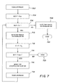
- Figure 7 shows the process flow for an automatic control mode of operation.
- the camera captures an image (step 702 ), and sets the adjustment voltage V to V min (step 704 ).
- the processor 314 checks the intensity of the image pixels to determine if there is a saturation region (where pixel intensity levels exceed T v ) in the image and checks the ratio R to determine if R > T N where R is the aforementioned ratio of the number of pixels whose intensity levels exceed T V to the total number of pixels of the image. If the answer is 'No', the processor 314 saves the image to storage 320 and the process stops at step 722.
- step 712 the processor 314 saves the image to storage 320 and increases the adjustment voltage V by an amount of ⁇ V (step 712).
- step 714 the processor 314 checks the feedback 332 from the auto controller 324 to see if the adjustment voltage V is less than V max . If the answer is 'Yes', the processor 314 commands the auto controller 324 to send the adjustment voltage V to the gate 328 . Another image is then captured and the process repeats. If the answer from step 714 is 'No', then the process stops.
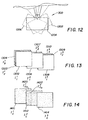
- FIG. 12 there is an exemplary operation showing a camera system ( 300 ) used for generating an extended dynamic range panorama moving from a first position 1202 , to a second position 1204 , then to a third position 1206 .
- the camera system 300 takes one or more images according to the above descriptions. Exemplary images are shown in Figure 13.
- the camera system 300 takes three images: image I 1 / 1 ( 1302 ), image I 1 / 2 (1303) and image I 1 / 3 (1304), where the superscript signifies the position of the camera.
- the camera system 300 takes two images: image I 2 / 1 (1306), and image I 2 / 2 (1307).
- the camera system 300 takes three images: image I 3 / 1 (1308), image I 3 / 2 (1309) and image I 3 / 3 (1310). These images are stored in storage 320 .
- Images collected in the storage 320 in the camera 300 are further processed for alignment and composition in an image processing system as shown in Figure 8.
- the digital images from the digital image storage 320 are provided to an image processor 802 , such as a programmable personal computer, or a digital image processing work station such as a Sun Sparc workstation.
- the image processor 802 may be connected to a CRT display 804 , an operator interface such as a keyboard 806 and a mouse 808 .
- the image processor 802 is also connected to a computer readable storage medium 807 .
- the image processor 802 transmits processed digital images to an output device 809 .
- the output device 809 can comprise a hard copy printer, a long-term image storage device, a connection to another processor, or an image telecommunication device connected, for example, to the Internet.
- the image processor 802 contains software for implementing the process of image alignment and composition, which is explained next.
- the preferred system for capturing multiple images at a specific position to form a extended dynamic range image does not capture all images simultaneously, so any unwanted motion in the camera or scene during the capture process will cause misalignment of the images.
- Correct formation of an extended dynamic range image assumes the camera is stable, or not moving, and that there is no scene motion during the capture of the collection of images. If the camera is mounted on a tripod or a monopod, or placed on top of or in contact with a stationary object, then the stability assumption is likely to hold. However, if the collection of images is captured while the camera is held in the hands of the photographer, the slightest jitter or movement of the hands may introduce stabilization errors that will adversely affect the formation of the extended dynamic range image.
- image stabilization The process of removing any unwanted motion from a sequence of images captured when the camera is at a specific position is called image stabilization.
- Some systems use optical, mechanical, or other physical means to correct for the unwanted motion at the time of capture or scanning. However, these systems are often complex and expensive.
- To provide stabilization for a generic digital image sequence several digital image processing methods have been developed and described in the prior art.
- a number of digital image processing methods use a specific camera motion model to estimate one or more parameters such as zoom, translation, rotation, etc. between successive frames in the sequences. These parameters are computed from a motion vector field that describes the correspondence between image points in two successive frames. The resulting parameters can then be filtered over a number of frames to provide smooth motion.
- An example of such a system is described in U.S. Patent No. 5,629,988, entitled “System and Method for Electronic Image Stabilization” and issued May 13, 1997 in the names of Burt et al, and which is incorporated herein by reference.
- a fundamental assumption in these systems is that a global transformation dominates the motion between adjacent frames.
- phase correlation for precisely aligning successive frames.
- An example of such a method has been reported by Eroglu et al. (in "A fast algorithm for subpixel accuracy image stabilization for digital film and video," Proc. SPIE Visual Communications and Image Processing, Vol. 3309, pp. 786 - 797, 1998). These methods would be more applicable to the stabilization of a collection of images used to form a extended dynamic range image because the correlation procedure only compares the information contained in the phase of the Fourier Transform of the images.
- FIG. 5 shows a flow chart of a system that unifies the previously explained manual control mode and auto control mode, and which includes the process of image alignment and composition.
- This system is capable of capturing, storing, and aligning a collection of images, where each image corresponds to a distinct luminance level.
- the extended dynamic range camera 300 is used to capture (step 500 ) an image of the scene. This captured image corresponds to the first luminance level, and is stored (step 502 ) in memory.
- a query 504 is made as to whether enough images have been captured to form the extended dynamic range image.
- a negative response to query 504 indicates that the degree of light attenuation is changed (step 506 ) e.g., by the auto controller 324 or by user adjustment of the manual controller 322 .
- steps 504 and 506 represent actions including manual voltage adjustment and the user's visual inspection of the result.
- steps 504 and 506 represent actions including automatic image saturation testing, automatic voltage adjustment, automatic voltage limit testing, etc., as stated in previous sections.
- step 502 stores images in the storage 320.
- the translational difference T j,j +1 (a two element vector corresponding to horizontal and vertical translation) between I j and I j+ 1 is computed by phase correlation 602 (as described in the aforementioned Eroglu reference, or in C. Kuglin and D. Hines, "The Phase Correlation Image Alignment Method", Proc. 1975 International Conference on Cybernetics and Society, pp. 163-165, 1975.) for each integral value of j for 1 ⁇ j ⁇ N - 1, where N is the total number of stored images.
- the counter i is initialized (step 604) to one, and image I i +1 is shifted (step 606), or translated by This shift corrects for the unwanted motion in image I i +1 found by the translational model.
- a negative response to query 608 indicates that i is incremented (step 610 ) by one, and the process continues at step 606 .
- An affirmative response to query 608 indicates that all images have been corrected (step 612 ) for unwanted motion, which completes step 508 .
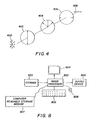
- Figure 9 shows exemplary contents of three images taken when the camera 300 is at the first position as shown in Figure 13.
- the first image, I 1 / 1, 902 is taken before manual or automatic light attenuation adjustment
- the second image, I 1 / 2, 904 is taken after a first manual or automatic light attenuation adjustment
- the third image, I 1 / 3, 906 is taken after a second manual or automatic light attenuation adjustment.
- Figure 9 only shows an exemplary set of images; the number of images (or adjustment steps) in a set could be, in theory, any positive integer.
- the first image 902 has a saturated region B 1 ( 922 ).
- the second image 904 has a saturated region B 2 (924), (where B 2 ⁇ B 1 ) .
- the third image 906 has no saturated region.
- Figure 9 shows a pixel 908 in the image 902, a pixel 910 in image 904, and a pixel 912 in the image 906.
- the pixels 908 , 910 , and 912 are aligned in the aforementioned image alignment step.
- Figure 9 shows that pixels 908 , 910 , and 912 reflect different illumination levels.
- the pixels 908, 910, and 912 are used in composition to produce a value for a composite image, I 1 / C , 942 at location 944.
- Image I 1 / C is also shown in Figure 14 as 1410.
- a composite image I 2 / C (1412) is generated from image I 2 / 1 ( 1306 ) and image I 2 / 2 (1307); at the third position, a composite image I 3 / C ( 1414 ) is generated from image I 3 / 1 ( 1308 ) , image I 3 / 2 ( 1309 ) and image I 3 / 3 (1310).
- the process of producing a value for a pixel in a composite image can be formulated as a robust statistical estimation Handbook for Digital Signal Processing by Mitra Kaiser, 1993).
- a set of pixels e.g. pixels 908, 910, and 912
- the computation of p est is simply where j 1 ⁇ [0, ⁇ N], j 2 ⁇ [0, ⁇ N ], subject to 0 ⁇ j 1 + j 2 ⁇ N.
- This formulation gives a robust estimation by excluding outliers (e.g. saturated pixels or dark pixels).
- a histogram of intensity levels of the composite image using the present invention is predicted to be like a curve 1156 shown in Fig. 11 (C) with a range of 0 (1152) to 255 (1158).
- the intensity distribution 1156 has a shape similar to intensity distribution curve 1116 of the original scene (Fig. 11(A)).
- the intensity resolution has been reduced from 1024 levels to 256 levels.
- the histogram of intensity levels would be as shown in Fig. 11(B), where considerable saturation is evident.
- Fig. 10 shows a flow chart corresponding to a preferred embodiment of the present invention for producing recoverable information that is to be used to generate a high bit-depth image from a low bit-depth capture device.
- the camera captures a first image in step 1002 .
- the processor 314 (automatic mode) or the user (manual mode) queries to see if there are saturated pixels in the image. If the answer is negative, the image is saved and the process terminates (step 1007 ). If the answer is affirmative the process proceeds to step 1008 , which determines if the image is a first image. If the image is a first image, the processor 314 stores the positions and intensity values of the unsaturated pixels in a first file.
- the locations of the saturated pixels are temporarily stored (step 1010 ) in a second file.
- the attenuator voltage is adjusted either automatically (by the auto controller 324 in Fig. 3) or manually (by the manual controller 322 in Fig. 3) as indicated in step 1011 . Adjustment and checking of voltage limits are carried out as previously described.
- step 1018 the processor 314 stores positions and intensity levels in the first file of only those pixels whose intensity levels were saturated in the previous image but are unsaturated in the current image. The pixels are referred to as "de-saturated" pixels.
- the processor 314 also stores the value of the associated transmission attenuation coefficient (V) defined in Equation (3).
- V transmission attenuation coefficient
- I k / i denote a captured image at position k, possibly having saturated pixels, where i ⁇ ⁇ 1, ⁇ ,M k ⁇ and M k is the total number of captured images M k ⁇ 1 . All captured images are assumed to contain the same number of pixels N and each pixel in a particular image I k / i at position k is identified by an index n , where n ⁇ ⁇ 1, ⁇ , N ⁇ .
- the subscript j ⁇ ⁇ 1, ⁇ , , J k / i ⁇ is associated with pixel index n ij in this subset where J k / i > 0 is the total number of saturated pixels in image I k / i .
- the exemplary images having saturated regions are the first image 902, denoted by I 1 / 1 and the second image 904, denoted by I 1 / 2.
- An exemplary last image I 1 / 3 in Fig. 9 is the third image 906.
- the processor 314 retrieves the locations of saturated pixels in image I k / i at position k that were temporarily stored in the second file. In step 1018 it checks to see if pixel n ij at location ( x nij , y nij ) has become de-saturated in the new current image.
- the new intensity level P k / i +1, ( x nij , y nij ) and the position ( x nij , y nij ) are stored in the first file along with the value of the associated attenuation coefficient, (V).
- the process of storing information on de-saturated pixels starts after a first adjustment of the attenuator control voltage and continues until a last adjustment is made.
- locations and intensities of unsaturated pixels of the first image 902 are stored in the first storage file (step 1009 ).
- the locations of saturated pixels in the region 922 are stored temporarily in the second storage file (step 1010 ).
- the second image 904 is captured (step 1016) after a first adjustment of the attenuator control voltage (step 1011 ).
- the processor 314 then retrieves from the second temporary storage file the locations of saturated pixels in the region 922 of the first image 902 . A determination is made automatically by the processor or manually by the operator to see if pixels at these locations have become de-saturated in the second image 904 .
- the first storage file is then updated with the positions and intensities of the newly de-saturated pixels (step 1018 ).
- pixel 908 is located in the saturated region 922 of the first image. This pixel corresponds to pixel 910 in the second image 904 , which lies in the de-saturated region 905 of the second image 904 .
- the intensities and locations of all pixels in the region 905 are stored in the first storage file along with the transmittance attenuation factor ( V) .
- V transmittance attenuation factor
- the process then loops back to step 1006.
- Information stored in the second temporary storage file is replaced by the locations of saturated pixels in the region 924 in the second image 904 (step 1010 ).
- a second and final adjustment of attenuator control voltage is made (step 1011 ) followed by the capture of the third image 906 (step 1016 ). Since all pixels in the region 924 have become newly de-saturated in the example, the first storage file is updated (step 1018) to include the intensities and locations of all pixels in this region along with the transmittance attenuation factor (V) . Since there are no saturated pixels in the third image 906, the process terminates (steps 1007) after the process loops back to step 1006 . It will be appreciated that only one attenuation coefficient needs to be stored for each adjustment of the attenuator control voltage, that is, for each new set of de-saturated pixels.
- the above described process is applied to k sets of images, where k ⁇ [1,..., K ], and K is the number of positions where the moving camera stops and takes images.
- Equation (4) expresses a piece of pseudo code describing this process at K positions.
- i is the image index
- n is the pixel index
- (x n , y n are the Cartesian co-ordinates of pixel n
- P k / i (x n , y n ) is the intensity in image I k / i , at the position k associated with pixel n
- n ij is the index associated with the j th saturated pixel in image I k / i .
- Another feature of the present invention is to use a low bit-depth device, such as the digital camera shown in Figures 1, 2 and 3, to generate extended dynamic range panorama (which as discussed to this point are still low bit-depth panorama), and at the same time, produce recoverable information that may be used to additionally generate high bit-depth panorama.
- a low bit-depth device such as the digital camera shown in Figures 1, 2 and 3, to generate extended dynamic range panorama (which as discussed to this point are still low bit-depth panorama), and at the same time, produce recoverable information that may be used to additionally generate high bit-depth panorama.
- Equation (4) it is a straightforward process to generate a high bit-depth image using the stored data.
- the exemplary data format in the file is for each row to have three elements: pixel position in Cartesian coordinates, pixel intensity and attenuation coefficient.
- the intensity data at position k in the file for each row by P k
- the position data by X k and attenuation coefficient by .
- new intensity data for a reconstructed high bit-depth image denoted by P k / HIGH .
- a simple reconstruction for K high bit depth images is shown as where is either 1 or (V) as indicated by Equation (4).
- the method of producing recoverable information to be used to generate a high bit-depth image described with the preferred embodiment can be modified for other types of extended dynamic range techniques such as controlling an integration time of a CCD sensor of a digital camera (see U.S. Patent No. 5,144,442, which is entitled “Wide Dynamic Range Camera” and issued September 1, 1992 in the name of Ran Ginosar et al).
- the transmittance attenuation coefficient is a function of time, that is, ( t ).
- the resultant composite images I k / C are used to generate the extended dynamic panorama of the scene. Note that every two neighboring two composite images have an overlapping region needed for stitching.
- An exemplary region is shown in Figure 14.
- the overall brightness and contrast in the overlapping region for two composite images are not the same due to the composite procedure discussed above.
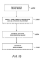
- two source digital images are provided in step 2200 .
- the pixel values of at least one of the source digital images are modified 2202 by a linear exposure transform so that the pixel values in the overlap regions of overlapping source digital images are similar, yielding a set of adjusted source digital images.
- a linear exposure transform refers to a transformation that is applied to the pixel values of a source digital image, the transformation being linear with respect to the scene intensity values at each pixel.
- the adjusted source digital images are then combined 2204 by a feathering scheme, weighted averages, or some other blending technique known in the art, to form a composite digital image 2206. After applying this process to all K composite images I k / C , the final composite image in step 2206 is the extended dynamic range panorama of the scene.
- This same transformation process can be applied to the reconstructed high bit depth image to generate a final high bit depth panorama of the scene.
Landscapes
- Physics & Mathematics (AREA)
- General Physics & Mathematics (AREA)
- Engineering & Computer Science (AREA)
- Theoretical Computer Science (AREA)
- Studio Devices (AREA)
- Image Processing (AREA)
- Studio Circuits (AREA)
- Editing Of Facsimile Originals (AREA)
- Facsimile Image Signal Circuits (AREA)
Abstract
Description






Claims (9)
- A method of obtaining an extended dynamic range panorama image of a scene from a plurality of limited dynamic range images captured by an image sensor in a digital camera, said method comprising steps of:(a) from a first position, capturing a first plurality of digital images comprising image pixels of the scene by exposing the image sensor to light transmitted from the scene as observed from the first position, wherein light transmittance upon the image sensor is adjustable;(b) evaluating each image after it is captured for an illumination level exceeding the limited dynamic range of the image at either a higher or a lower end of the dynamic range for at least some of the image pixels;(c) based on the evaluation of each image exceeding the limited dynamic range, adjusting the light transmittance upon the image sensor in order to obtain a subsequent digital image having a different scene brightness range;(d) storing the first plurality of digital images;(e) processing the stored digital images to generate a first composite image having an extended dynamic range greater than any of the digital images by themselves;(f) from a second position, capturing a second plurality of digital images comprising image pixels of the scene by exposing the image sensor to light transmitted from the scene as observed from the second position, and then repeating the steps (b) through (e) for the second plurality of images to generate a second composite image; and(g) processing the first and second composite images to generate an extended dynamic range panorama image.
- The method as claimed in claim 1 wherein the step (b) of evaluating each image after it is captured comprises evaluating each image for an illumination level indicative of saturated regions of the image.
- The method as claimed in claim 1 wherein the step (b) of evaluating each image after it is captured comprises displaying each image after it is captured and evaluating the displayed image for an illumination level indicative of one or more regions of the image exceeding the limited dynamic range of the image.
- A system for obtaining an extended dynamic range panorama image of a scene from a plurality of limited dynamic range images of the scene captured by a digital camera, said system comprising:a camera having (a) an image sensor for capturing a plurality of digital images comprising image pixels of the scene by exposing the image sensor to light transmitted from the scene, wherein light transmittance upon the image sensor is adjustable; (b) means for evaluating each image after it is captured for an illumination level exceeding the limited dynamic range of the image for at least some of the image pixels; (c) a controller for adjusting the light transmittance upon the image sensor in order to obtain a subsequent digital image having a different scene brightness range, whereby said controller is operative based on the evaluation of each image exceeding the limited dynamic range; and (d) a storage device for storing the plurality of digital images, whereby the camera is operated in a plurality of positions to capture respective pluralities of digital images comprising image pixels of the scene as observed from the plurality of positions; andan offline processor for (a) processing the respective pluralities of stored images to generate a plurality of composite images, each having an extended dynamic range greater than any of the digital images by themselves and (b) processing the plurality of composite images to generate an extended dynamic range panorama image.
- The system as claimed in claim 4 wherein said means for evaluating each image after it is captured evaluates each image for an illumination level indicative of saturated regions of the image.
- The system as claimed in claim 4 wherein said means for evaluating each image after it is captured comprises a display device for displaying each image after it is captured and said controller comprises a manual controller for adjusting the light transmittance upon the image sensor.
- The system as claimed in claim 4 wherein said means for evaluating each image after it is captured comprises a digital processor for automatically evaluating each image for an illumination level indicative of one or more regions of the image exceeding the limited dynamic range of the image and for generating a control signal indicative of the evaluation, and said controller comprises an automatic controller responsive to the control signal for adjusting the light transmittance upon the image sensor.
- A method of obtaining a high bit depth panorama image of a scene from images of lower bit depth of the scene captured by an image sensor in a digital camera, said lower bit depth images also comprising lower dynamic range images, said method comprising steps of:(a) from a first position, capturing a first plurality of digital images of lower bit depth comprising image pixels of the scene by exposing the image sensor to light transmitted from the scene as observed from the first position, wherein light transmittance upon the image sensor is variably attenuated for at least one of the images;(b) evaluating each image after it is captured for an illumination level exceeding the limited dynamic range of the image for at least some of the image pixels;(c) based on the evaluation of each image exceeding the limited dynamic range, adjusting the light transmittance upon the image sensor in order to obtain a subsequent digital image having a different scene brightness range;(d) calculating an attenuation coefficient for each of the images corresponding to the degree of attenuation for each image;(e) storing data for the reconstruction of one or more high bit depth images from the low bit depth images, said data including the first plurality of digital images and the attenuation coefficients;(f) processing the stored data to generate a first composite image having a higher bit depth than any of the digital images by themselves;(g) from a second position, capturing a second plurality of digital images of lower bit depth comprising image pixels of the scene by exposing the image sensor to light transmitted from the scene as observed from the second position, and then repeating the steps (b) through (f) on the second plurality of images to generate a second composite image; and(h) processing the first and second composite images to generate a panorama image having a higher bit depth.
- The method as claimed in claim 8 wherein the step (e) of storing data for the reconstruction of a high bit depth image comprises the steps of:storing intensity values for de-saturated pixels obtained by changing light transmittance in step (c);storing image positions for the de-saturated pixels obtained by changing light transmittance in step (c);storing a transmittance attenuation coefficient associated with de-saturated pixels obtained by changing light transmittance in step (c);storing intensity values for unsaturated pixels;storing image positions for the unsaturated pixels captured in step (a); andstoring a transmittance attenuation coefficient associated with unsaturated pixels.
Applications Claiming Priority (2)
| Application Number | Priority Date | Filing Date | Title |
|---|---|---|---|
| US10/302,033 US20040100565A1 (en) | 2002-11-22 | 2002-11-22 | Method and system for generating images used in extended range panorama composition |
| US302033 | 2002-11-22 |
Publications (2)
| Publication Number | Publication Date |
|---|---|
| EP1422660A2 true EP1422660A2 (en) | 2004-05-26 |
| EP1422660A3 EP1422660A3 (en) | 2005-01-05 |
Family
ID=32229911
Family Applications (1)
| Application Number | Title | Priority Date | Filing Date |
|---|---|---|---|
| EP03078465A Withdrawn EP1422660A3 (en) | 2002-11-22 | 2003-11-03 | Method and system for generating images used in extended range panorama composition |
Country Status (3)
| Country | Link |
|---|---|
| US (1) | US20040100565A1 (en) |
| EP (1) | EP1422660A3 (en) |
| JP (1) | JP2004180308A (en) |
Cited By (7)
| Publication number | Priority date | Publication date | Assignee | Title |
|---|---|---|---|---|
| EP1686531A1 (en) | 2005-01-27 | 2006-08-02 | Siemens Aktiengesellschaft | A method, a software product and an electronic device for generating an image composition |
| WO2008029864A1 (en) * | 2006-09-06 | 2008-03-13 | Casio Computer Co., Ltd. | Image pickup apparatus |
| EP1771811A4 (en) * | 2004-07-26 | 2010-06-09 | Silicon Optix Inc | Panoramic vision system and method |
| US9077910B2 (en) | 2011-04-06 | 2015-07-07 | Dolby Laboratories Licensing Corporation | Multi-field CCD capture for HDR imaging |
| GB2543932A (en) * | 2015-09-23 | 2017-05-03 | Agilent Technologies Inc | High dynamic range infrared imaging spectrometer |
| CN107438174A (en) * | 2017-07-17 | 2017-12-05 | 惠州市德赛西威汽车电子股份有限公司 | A kind of brightness uniformity adjusting method of panorama backing system |
| EP2498102B1 (en) * | 2011-03-07 | 2019-04-24 | Kabushiki Kaisha TOPCON | Panoramic Image Preparing Method and Three-Dimensional Laser Scanner |
Families Citing this family (41)
| Publication number | Priority date | Publication date | Assignee | Title |
|---|---|---|---|---|
| US6879731B2 (en) * | 2003-04-29 | 2005-04-12 | Microsoft Corporation | System and process for generating high dynamic range video |
| WO2007138007A1 (en) * | 2006-05-29 | 2007-12-06 | Bit-Side Gmbh | Method and arrangement for processing records of imaging sensors, corresponding computer program, and corresponding computer-readable storage medium |
| WO2009050594A2 (en) * | 2007-07-25 | 2009-04-23 | Yunn-En Yeo | Exposure control for an imagning system |
| JP4772009B2 (en) * | 2007-08-07 | 2011-09-14 | 三洋電機株式会社 | Digital camera |
| US8724921B2 (en) * | 2008-05-05 | 2014-05-13 | Aptina Imaging Corporation | Method of capturing high dynamic range images with objects in the scene |
| JP2010074535A (en) * | 2008-09-18 | 2010-04-02 | Fujifilm Corp | Photographing apparatus and photographing method |
| TWI397003B (en) * | 2008-10-23 | 2013-05-21 | Pixart Imaging Inc | Image processing method for optical navigator and optical navigator using the same |
| JP5096297B2 (en) * | 2008-11-28 | 2012-12-12 | 株式会社キーエンス | Imaging device |
| CN101763175B (en) * | 2008-12-23 | 2013-07-03 | 原相科技股份有限公司 | Image processing method of displacement detection device and displacement detection device using the method |
| EP2385705A4 (en) | 2008-12-30 | 2011-12-21 | Huawei Device Co Ltd | Method and device for generating stereoscopic panoramic video stream, and method and device of video conference |
| US20100265313A1 (en) * | 2009-04-17 | 2010-10-21 | Sony Corporation | In-camera generation of high quality composite panoramic images |
| WO2011014419A1 (en) * | 2009-07-31 | 2011-02-03 | 3Dmedia Corporation | Methods, systems, and computer-readable storage media for creating three-dimensional (3d) images of a scene |
| US9380292B2 (en) | 2009-07-31 | 2016-06-28 | 3Dmedia Corporation | Methods, systems, and computer-readable storage media for generating three-dimensional (3D) images of a scene |
| US20110025830A1 (en) * | 2009-07-31 | 2011-02-03 | 3Dmedia Corporation | Methods, systems, and computer-readable storage media for generating stereoscopic content via depth map creation |
| US9344701B2 (en) | 2010-07-23 | 2016-05-17 | 3Dmedia Corporation | Methods, systems, and computer-readable storage media for identifying a rough depth map in a scene and for determining a stereo-base distance for three-dimensional (3D) content creation |
| JP5409577B2 (en) | 2010-10-05 | 2014-02-05 | 株式会社ソニー・コンピュータエンタテインメント | Panorama image generation apparatus and panorama image generation method |
| WO2012061549A2 (en) | 2010-11-03 | 2012-05-10 | 3Dmedia Corporation | Methods, systems, and computer program products for creating three-dimensional video sequences |
| US10200671B2 (en) | 2010-12-27 | 2019-02-05 | 3Dmedia Corporation | Primary and auxiliary image capture devices for image processing and related methods |
| US8274552B2 (en) | 2010-12-27 | 2012-09-25 | 3Dmedia Corporation | Primary and auxiliary image capture devices for image processing and related methods |
| JP5678324B2 (en) | 2011-02-10 | 2015-03-04 | パナソニックIpマネジメント株式会社 | Display device, computer program, and display method |
| JP5655667B2 (en) * | 2011-03-31 | 2015-01-21 | カシオ計算機株式会社 | Imaging apparatus, imaging control method, image processing apparatus, image processing method, and program |
| US9036042B2 (en) | 2011-04-15 | 2015-05-19 | Dolby Laboratories Licensing Corporation | Encoding, decoding, and representing high dynamic range images |
| US8334911B2 (en) | 2011-04-15 | 2012-12-18 | Dolby Laboratories Licensing Corporation | Encoding, decoding, and representing high dynamic range images |
| US20130044237A1 (en) * | 2011-08-15 | 2013-02-21 | Broadcom Corporation | High Dynamic Range Video |
| JP5860304B2 (en) * | 2012-02-23 | 2016-02-16 | キヤノン株式会社 | Imaging apparatus, control method therefor, program, and storage medium |
| EP2946249B1 (en) * | 2013-01-15 | 2018-05-23 | Avigilon Corporation | Imaging apparatus with scene adaptive auto exposure compensation |
| US10021295B1 (en) * | 2013-06-03 | 2018-07-10 | Amazon Technologies, Inc. | Visual cues for managing image capture |
| JP6415028B2 (en) * | 2013-07-12 | 2018-10-31 | キヤノン株式会社 | IMAGING DEVICE, IMAGING DEVICE CONTROL METHOD, AND PROGRAM |
| DE102014207315A1 (en) * | 2014-04-16 | 2015-10-22 | Spheronvr Ag | camera assembly |
| US9286653B2 (en) * | 2014-08-06 | 2016-03-15 | Google Inc. | System and method for increasing the bit depth of images |
| JP2016163052A (en) * | 2015-02-26 | 2016-09-05 | オリンパス株式会社 | Image processing apparatus, imaging device, image processing method, and image processing program |
| JP6611509B2 (en) * | 2015-08-05 | 2019-11-27 | キヤノン株式会社 | Image processing apparatus, imaging apparatus, and image processing program |
| JP2017108309A (en) * | 2015-12-10 | 2017-06-15 | オリンパス株式会社 | Imaging apparatus and imaging method |
| CN105976325A (en) * | 2016-06-29 | 2016-09-28 | 上海小蚁科技有限公司 | Method for adjusting brightness of multiple images |
| CN107800979B (en) * | 2017-10-23 | 2019-06-28 | 深圳看到科技有限公司 | High dynamic range video image pickup method and filming apparatus |
| US11128809B2 (en) | 2019-02-15 | 2021-09-21 | Samsung Electronics Co., Ltd. | System and method for compositing high dynamic range images |
| US11062436B2 (en) | 2019-05-10 | 2021-07-13 | Samsung Electronics Co., Ltd. | Techniques for combining image frames captured using different exposure settings into blended images |
| US10911691B1 (en) | 2019-11-19 | 2021-02-02 | Samsung Electronics Co., Ltd. | System and method for dynamic selection of reference image frame |
| US11430094B2 (en) | 2020-07-20 | 2022-08-30 | Samsung Electronics Co., Ltd. | Guided multi-exposure image fusion |
| JP7678673B2 (en) * | 2021-01-26 | 2025-05-16 | キヤノン株式会社 | Imaging device, electronic device, and image generating device |
| CN117793325B (en) * | 2024-02-26 | 2024-04-19 | 南京维赛客网络科技有限公司 | Method, system and storage medium for switching panoramic pictures in step roaming |
Family Cites Families (20)
| Publication number | Priority date | Publication date | Assignee | Title |
|---|---|---|---|---|
| JPS60160947A (en) * | 1984-02-01 | 1985-08-22 | 株式会社モリタ製作所 | Panorama x-ray photographing apparatus |
| IL87306A0 (en) * | 1988-08-02 | 1989-01-31 | Technion Res & Dev Foundation | Wide dynamic range camera |
| US5247366A (en) * | 1989-08-02 | 1993-09-21 | I Sight Ltd. | Color wide dynamic range camera |
| JPH05506971A (en) * | 1990-02-16 | 1993-10-07 | スキャネラ ソシエテ シビル | Device for increasing the dynamic range of cameras |
| ES2258311T3 (en) * | 1993-06-04 | 2006-08-16 | Sarnoff Corporation | SYSTEM AND PROCEDURE FOR ELECTRONIC STABILIZATION OF IMAGES. |
| US5953082A (en) * | 1995-01-18 | 1999-09-14 | Butcher; Roland | Electro-optical active masking filter using see through liquid crystal driven by voltage divider photosensor |
| US5929908A (en) * | 1995-02-03 | 1999-07-27 | Canon Kabushiki Kaisha | Image sensing apparatus which performs dynamic range expansion and image sensing method for dynamic range expansion |
| US5828793A (en) * | 1996-05-06 | 1998-10-27 | Massachusetts Institute Of Technology | Method and apparatus for producing digital images having extended dynamic ranges |
| JPH1042182A (en) * | 1996-07-26 | 1998-02-13 | Canon Inc | Imaging device |
| JPH114398A (en) * | 1997-06-11 | 1999-01-06 | Hitachi Ltd | Digital wide camera |
| JPH1165004A (en) * | 1997-08-12 | 1999-03-05 | Sony Corp | Panoramic imaging system |
| US6128108A (en) * | 1997-09-03 | 2000-10-03 | Mgi Software Corporation | Method and system for compositing images |
| EP0910209B1 (en) * | 1997-10-17 | 2010-04-14 | Panasonic Corporation | A video camera having an increased dynamic range |
| US6501504B1 (en) * | 1997-11-12 | 2002-12-31 | Lockheed Martin Corporation | Dynamic range enhancement for imaging sensors |
| US6657667B1 (en) * | 1997-11-25 | 2003-12-02 | Flashpoint Technology, Inc. | Method and apparatus for capturing a multidimensional array of overlapping images for composite image generation |
| US6304284B1 (en) * | 1998-03-31 | 2001-10-16 | Intel Corporation | Method of and apparatus for creating panoramic or surround images using a motion sensor equipped camera |
| US6864916B1 (en) * | 1999-06-04 | 2005-03-08 | The Trustees Of Columbia University In The City Of New York | Apparatus and method for high dynamic range imaging using spatially varying exposures |
| US6978051B2 (en) * | 2000-03-06 | 2005-12-20 | Sony Corporation | System and method for capturing adjacent images by utilizing a panorama mode |
| KR100591144B1 (en) * | 2001-02-09 | 2006-06-19 | 이구진 | Method and apparatus for omni-directional image and 3-dimensional data acquisition with data annotation |
| US20030086002A1 (en) * | 2001-11-05 | 2003-05-08 | Eastman Kodak Company | Method and system for compositing images |
-
2002
- 2002-11-22 US US10/302,033 patent/US20040100565A1/en not_active Abandoned
-
2003
- 2003-11-03 EP EP03078465A patent/EP1422660A3/en not_active Withdrawn
- 2003-11-25 JP JP2003394023A patent/JP2004180308A/en active Pending
Cited By (11)
| Publication number | Priority date | Publication date | Assignee | Title |
|---|---|---|---|---|
| EP1771811A4 (en) * | 2004-07-26 | 2010-06-09 | Silicon Optix Inc | Panoramic vision system and method |
| EP1686531A1 (en) | 2005-01-27 | 2006-08-02 | Siemens Aktiengesellschaft | A method, a software product and an electronic device for generating an image composition |
| WO2008029864A1 (en) * | 2006-09-06 | 2008-03-13 | Casio Computer Co., Ltd. | Image pickup apparatus |
| EP2498102B1 (en) * | 2011-03-07 | 2019-04-24 | Kabushiki Kaisha TOPCON | Panoramic Image Preparing Method and Three-Dimensional Laser Scanner |
| US9077910B2 (en) | 2011-04-06 | 2015-07-07 | Dolby Laboratories Licensing Corporation | Multi-field CCD capture for HDR imaging |
| US9549123B2 (en) | 2011-04-06 | 2017-01-17 | Dolby Laboratories Licensing Corporation | Multi-field CCD capture for HDR imaging |
| GB2543932A (en) * | 2015-09-23 | 2017-05-03 | Agilent Technologies Inc | High dynamic range infrared imaging spectrometer |
| US10184835B2 (en) | 2015-09-23 | 2019-01-22 | Agilent Technologies, Inc. | High dynamic range infrared imaging spectroscopy |
| GB2543932B (en) * | 2015-09-23 | 2020-08-12 | Agilent Technologies Inc | High dynamic range infrared imaging spectrometer |
| CN107438174A (en) * | 2017-07-17 | 2017-12-05 | 惠州市德赛西威汽车电子股份有限公司 | A kind of brightness uniformity adjusting method of panorama backing system |
| CN107438174B (en) * | 2017-07-17 | 2020-04-07 | 惠州市德赛西威汽车电子股份有限公司 | Brightness uniformity adjusting method of panoramic reversing system |
Also Published As
| Publication number | Publication date |
|---|---|
| JP2004180308A (en) | 2004-06-24 |
| EP1422660A3 (en) | 2005-01-05 |
| US20040100565A1 (en) | 2004-05-27 |
Similar Documents
| Publication | Publication Date | Title |
|---|---|---|
| EP1422660A2 (en) | Method and system for generating images used in extended range panorama composition | |
| EP1418544A1 (en) | Method and apparatus for generating images used in extended range image composition | |
| US7529424B2 (en) | Correction of optical distortion by image processing | |
| US6856708B1 (en) | Method and system for composing universally focused image from multiple images | |
| CN1213602C (en) | Video equipment with fast digital pan-tilt zoom | |
| JP5367640B2 (en) | Imaging apparatus and imaging method | |
| US8125537B2 (en) | Image processing method and imaging apparatus using the same | |
| US20090310885A1 (en) | Image processing apparatus, imaging apparatus, image processing method and recording medium | |
| US20140063287A1 (en) | Imaging apparatus | |
| EP2536125B1 (en) | Imaging device and method, and image processing method for imaging device | |
| US10591711B2 (en) | Microscope and method for obtaining a high dynamic range synthesized image of an object | |
| EP1734747A1 (en) | Image-processing apparatus and image-pickup apparatus | |
| WO2008053765A1 (en) | Image generating device and image generating method | |
| WO2007049634A1 (en) | Imaging device, image processing device, and program | |
| JP2017143390A (en) | Image processing apparatus and method | |
| JP3950188B2 (en) | Image distortion correction parameter determination method and imaging apparatus | |
| CN107734271B (en) | 1,000,000,000 pixel video generation method of high dynamic range | |
| JP5096297B2 (en) | Imaging device | |
| US3535443A (en) | X-ray image viewing apparatus | |
| CN110276714B (en) | Method and device for synthesizing rapid scanning panoramic image | |
| US20060023276A1 (en) | Digital imaging apparatus capable of creating panorama image and a creating method thereof | |
| Mannami et al. | High dynamic range camera using reflective liquid crystal | |
| JP7458769B2 (en) | Image processing device, imaging device, image processing method, program and recording medium | |
| JP7409604B2 (en) | Image processing device, imaging device, image processing method, program and recording medium | |
| JP2009047734A (en) | Imaging apparatus and image processing program |
Legal Events
| Date | Code | Title | Description |
|---|---|---|---|
| PUAI | Public reference made under article 153(3) epc to a published international application that has entered the european phase |
Free format text: ORIGINAL CODE: 0009012 |
|
| AK | Designated contracting states |
Kind code of ref document: A2 Designated state(s): AT BE BG CH CY CZ DE DK EE ES FI FR GB GR HU IE IT LI LU MC NL PT RO SE SI SK TR |
|
| AX | Request for extension of the european patent |
Extension state: AL LT LV MK |
|
| PUAL | Search report despatched |
Free format text: ORIGINAL CODE: 0009013 |
|
| AK | Designated contracting states |
Kind code of ref document: A3 Designated state(s): AT BE BG CH CY CZ DE DK EE ES FI FR GB GR HU IE IT LI LU MC NL PT RO SE SI SK TR |
|
| AX | Request for extension of the european patent |
Extension state: AL LT LV MK |
|
| RIC1 | Information provided on ipc code assigned before grant |
Ipc: 7G 06T 5/50 B Ipc: 7G 06T 3/00 A |
|
| 17P | Request for examination filed |
Effective date: 20050506 |
|
| AKX | Designation fees paid |
Designated state(s): DE FR GB |
|
| 17Q | First examination report despatched |
Effective date: 20071121 |
|
| STAA | Information on the status of an ep patent application or granted ep patent |
Free format text: STATUS: THE APPLICATION IS DEEMED TO BE WITHDRAWN |
|
| 18D | Application deemed to be withdrawn |
Effective date: 20080326 |