EP1422581A2 - Hand position detecting device and electronic timepiece provided therewith - Google Patents
Hand position detecting device and electronic timepiece provided therewith Download PDFInfo
- Publication number
- EP1422581A2 EP1422581A2 EP03257333A EP03257333A EP1422581A2 EP 1422581 A2 EP1422581 A2 EP 1422581A2 EP 03257333 A EP03257333 A EP 03257333A EP 03257333 A EP03257333 A EP 03257333A EP 1422581 A2 EP1422581 A2 EP 1422581A2
- Authority
- EP
- European Patent Office
- Prior art keywords
- light
- wheel
- hand
- hand wheel
- regions
- Prior art date
- Legal status (The legal status is an assumption and is not a legal conclusion. Google has not performed a legal analysis and makes no representation as to the accuracy of the status listed.)
- Withdrawn
Links
Images




Classifications
-
- G—PHYSICS
- G04—HOROLOGY
- G04C—ELECTROMECHANICAL CLOCKS OR WATCHES
- G04C9/00—Electrically-actuated devices for setting the time-indicating means
-
- G—PHYSICS
- G04—HOROLOGY
- G04C—ELECTROMECHANICAL CLOCKS OR WATCHES
- G04C17/00—Indicating the time optically by electric means
-
- G—PHYSICS
- G04—HOROLOGY
- G04C—ELECTROMECHANICAL CLOCKS OR WATCHES
- G04C3/00—Electromechanical clocks or watches independent of other time-pieces and in which the movement is maintained by electric means
- G04C3/14—Electromechanical clocks or watches independent of other time-pieces and in which the movement is maintained by electric means incorporating a stepping motor
Definitions
- the present invention relates to a hand position detecting device for a timepiece and to an electronic timepiece provided with the device.
- a hand position detecting device for detecting that hands such as second hand, minute hand, and hour hand have been once returned to their initial positions (e.g., the position of just 12 o'clock) is known in a timepiece having a radio correction function of correcting the time by receiving standard radio waves including time information.
- a light-emitting device, a light-receiving device, and a reflective surface are so arranged that hand wheels whose rotational positions are to be detected are interposed among them.
- the reflective surface that gives information about the initial position is present at one location and so where all of the hour wheel, minute wheel, and second wheel are rotationally driven by one motor, it is necessary to rotationally drive the hands by amounts corresponding to 12 hours at a maximum to set the hands to their initial positions. Furthermore, while they are being rotationally driven, it is necessary to keep electrically feeding the light-emitting and light-receiving devices, as well as the motor and its rotational driver circuit. Accordingly, the time taken to place them in their initial positions is prolonged. In addition, where the driving source is a battery, it is difficult to neglect the energy consumption.
- the present invention has been made in view of the foregoing. It is an object to provide a hand position detecting device capable of minimizing the rotation (the amount by which the motor is rotationally driven or the number of driving steps) of hand wheels necessary to ascertain their initial positions and also to provide an electronic timepiece provided with this device.
- the hand position detecting device of the present invention in which, when first hand wheel and a second hand wheel which is rotated in response to rotation of the first hand wheel so as to make one rotation as the first hand wheel makes an integral number of rotations, have reached given positions, light from a light-emitting device is made to hit regions formed in the second hand wheel permitting light detection via an aperture formed in the first hand wheel to pass incident light and the light made detectable from the regions permitting light detection is detected by a light-receiving device.
- the second hand wheel has the plural regions permitting light detection, the regions being angularly unequally spaced from each other such that the light-receiving device receives the light made detectable when the second hand wheel is also at plural intermediate rotational positions other than the given positions.
- the hour wheel has the plural regions permitting light detection for light-receiving device to receive the light made detectable when it is also at plural intermediate rotational positions other than the given positions. Therefore, the rotational angle of the second hand wheel or the time (the amount by which the motor is rotationally driven or the number of driving steps) required to detect the regions permitting light detection can be small. Furthermore, in the hand position detecting device of the invention, “the second hand wheel has the plural regions permitting light detection, the regions being angularly unequally spaced from each other".
- the position of the second hand wheel can be identified simply by detecting the rotational angle of the second hand wheel necessary to detect the next region permitting light detection (typically, a region permitting light detection is detected twice). Consequently, the second hand wheel can be set in a given position or another given position having a given positional relation (angular relation) to the former given position simply by rotating the second hand wheel through an angle corresponding to the given position based on the identified position. Hence, the angle through which the hand wheel is rotated to place the hand wheel into the given position or another given position as described above can be reduced to a minimum. In addition, the time required to place the hand wheel in position as described above can be minimized. Also, the energy consumption can be reduced to a minimum.
- the initial position typically corresponds to the given position.
- the initial position may also be the aforementioned another given position having a certain positional relation to the first-mentioned given position.
- the regions of the second hand wheel permitting light detection may be either reflective surfaces that reflect incident light and produce reflected light or light transmissive regions (apertures or regions made of a light transmissive material) that transmit incident light and produce transmitted light.
- the light made detectable is reflected light.
- the light-receiving device is constructed to detect the reflected light reflected by the reflective surfaces via the aperture in the first hand wheel to pass reflected light.
- incidence and reflection may be made obliquely relative to the reflective surfaces or substantially perpendicular to the reflective surfaces.
- the device is so constructed that when the first and second hand wheels have reached given positions, light from the light-emitting device obliquely hits the reflective surfaces on the second hand wheel via the aperture in the first hand wheel to pass incident light.
- Reflected light reflected obliquely by the reflective surfaces is detected by the light-receiving device via the aperture in the first hand wheel, the aperture being used for passage of reflected light.
- the aperture for passage of incident light and the aperture for passage of reflected light consist of the same shared aperture.
- the light made detectable is a transmitted hole passed through the light transmissive regions of the second hand wheel.
- the light-receiving device detects the transmitted hole from the light transmissive regions.
- the angular interval between the regions of the second hand wheel permitting detection is set to an integral multiple of an incremental rotation angle through which the second hand wheel rotates when the first hand wheel makes one rotation.
- the first hand wheel is typically a minute wheel and the second hand wheel is an hour wheel.
- the first hand wheel may be a second hand wheel, and the second hand wheel may be a minute wheel.
- a set in which the first hand wheel is a minute wheel and the second hand wheel is an hour wheel and another set in which the first hand wheel is a second hand wheel and the second hand wheel is a minute wheel may be combined.
- the angular interval between the regions of the hour wheel permitting detection is typically an integral multiple of the incremental angle, i.e., 30 degrees, through which the hour wheel acting as the second hand wheel rotates when the minute wheel acting as the first hand wheel makes one rotation.
- the minute wheel can be set at positions shifted by amounts that are precisely integral multiples of 1 hour, i.e., at the same position as the given positions.
- the hour wheel is provided with the regions permitting detection, the regions being angularly spaced from each other by amounts equal to integral multiples of 30 degrees. Therefore, events permitting detection with the hour wheel such as reflection are obtained at rotational positions shifted in time by integral multiples of 1 hour.
- the minute wheel returns to the same position in a time shifted by an integral multiple of 1 hour. Therefore, when the rotational position of the hour wheel is detected, the minute wheel is automatically placed in position. Also, where the second wheel other than the minute wheel is placed in position at the same time, the same circumstance holds. Moreover, where an intermediate wheel for mating together the hour and minute wheels and an intermediate wheel for mating together the minute and second wheels are placed in position simultaneously, the same circumstance holds.
- the hour wheel typically has four regions (typically, reflective surfaces) permitting detection, the regions being spaced from each other in the direction of rotation.
- the four regions include a reference position where incident light from the light-emitting device is supplied as light made detectable (typically, reflected light) to the light-receiving device when the hour wheel is in a given position.
- the angular intervals between any adjacent regions,one of the four regions permitting detection are typically 30 degrees, 60 degrees, 120 degrees, and 150 degrees.
- the position of the hand wheel can be identified simply by rotating the hour wheel about 180 degrees (corresponding to 6 hours) at a maximum.
- the hand wheel can be quickly placed in position. Also, the energy consumption can be suppressed to a minimum.
- the angular intervals between any adjacent regions of the four regions (e.g., reflective surfaces) permitting detection may be 30 degrees, 60 degrees, 90 degrees, and 180 degrees, instead of 30 degrees, 60 degrees, 120 degrees, and 150 degrees.
- the hour wheel may have three regions (e.g., reflective surfaces) permitting detection, the three regions being unequally spaced from each other in the direction of rotation.
- the three regions include a reference position where incident light from the light-emitting device is supplied as light made detectable (e.g., reflected light) to the light-receiving device when the hour wheel is in a given position.
- the light-emitting device and light-receiving device are once stopped from being driven.
- the light-emitting and light-receiving devices are driven during the time required to detect whether the light from the light-emitting device is received by the light-receiving device or not in the rotational position.
- the light-emitting and light-receiving devices are driven by electrically feeding them practically during a time for which the hand wheels (hour wheel and minute wheel) are required to be rotated to detect the first region permitting detection.
- the consumption of energy required to drive the light-emitting and light-receiving devices can be suppressed to a minimum. Consequently, in a battery-driven case, the consumption of the battery can be reduced to a minimum. That is, when the reflective surface is detected second time, it is only necessary to perform one detection as to whether reception of light is present or not whenever a rotation corresponding to 1 hour is made. Consequently, the light-emitting and light-receiving devices are only required to be driven like sampling whenever a rotation corresponding to 1 hour is made. Thus, the consumption of energy required to drive the light-emitting and light-receiving devices can be suppressed to a negligible extent.
- the hand position detecting device of the invention is so configured that light from the light-emitting device hits the reflective surfaces obliquely, is reflected obliquely at the reflective surfaces, and enters the light-receiving device, a V-shaped optical path is formed as a whole. If the gap or the thickness between the mounting portions of the circuit board where the light-emitting and light-receiving devices are mounted and the reflective surfaces is relatively small, the gap between the light-emitting and light-receiving devices can be made relatively large. This reduces the danger that the light-receiving device receives stray light.
- the incidence angle and reflection angle at the reflective surfaces are typically about 30 degrees, for example.
- the angles may be about 45 degrees or about 60 degrees in some cases, or even greater.
- the incidence angle and reflection angle may be set smaller. For example, they may be about 15 degrees or less.
- the aperture for passage of incident light and the aperture for passage of reflected light are typically separated by a partitional wall portion. In this case, there is little danger that incident light passed through the aperture for passage of incident light erroneously reaches the aperture for passage of reflected light and so the danger that the light-receiving device receives stray light can be suppressed to a minimum.
- the aperture portion forming the aperture for passage of incident light and the aperture portion forming the aperture for passage of reflected light together form one elongated continuous aperture.
- both minute and second wheels have the aperture for passage of incident light and the aperture for passage of reflected light and the minute wheel is located close to the hour wheel having reflective surfaces, for example, even if the aperture in the minute wheel for passage of incident light and the aperture for passage of reflected light together form one elongated continuous aperture, the second wheel located remotely from the reflective surfaces typically has two apertures separated from each other.
- the apertures may be holes or windows made of a material transparent to the used light.
- the hand position detecting device of the invention is so configured that light from the light-emitting device is made to hit the reflective surfaces obliquely, is reflected obliquely at the reflective surfaces, and enters the light-receiving device
- the direction in which the light-emitting and light-receiving devices are spaced from each other is set to a direction intersecting the radial direction of the minute wheel and hour wheel whose rotational positions should be detected, typically set to a direction perpendicular to the radial direction, to avoid increase of the size of the device.
- the space between the aperture in a rotating part such as a gear to pass incident light and the aperture to pass reflected light can be set large for the diameter of the rotating part.
- the space between the light-emitting device and light-receiving device can be set relatively large. This can reduce the danger that the light-receiving device receives stray light. That the direction in which the light-emitting and light-receiving devices are spaced from each other is set to intersect the radial direction of the minute wheel and hour wheel whose rotational positions should be detected (typically set to a sense perpendicular to the radial direction) means that the angle connecting the light-emitting and light-receiving devices is oblique (typically, at right angles) relative to the angle connecting the center axes of rotation of two gears in a case where the rotational positions of the two gears provided with the center axes of rotation parallel to each other are detected at the same time, for example.
- a signal P1 from a noscillator circuit 10 is frequency-divided by a frequency divider circuit 11 into a pulse signal P2.
- a control circuit 12 including a microprocessor 13 and a memory 14 sends a drive-and-control signal P3 to a motor driver circuit 15.
- a motor 16 is rotated in accordance with a driver signal P4 owing to the motor driver circuit 15.
- a wheel train 17 mated to the output shaft of the motor 16 is rotated.
- the wheel train 17 includes intermediate wheel trains and hand wheels such as a second wheel 23, a minute wheel 24 acting as a first hand wheel, and an hour wheel 25 (Figs.
- the memory 14 includes a ROM (read-only memory) portion 55 loaded with a program 50 for detecting hand positions as shown in the flowchart of Fig. 4 and a RAM portion 52 becoming a working region.
- a hand wheel relative position data storage portion 53 and a reflective surface interval counter 54 are formed in the RAM portion 52.
- the output pulses P2 from the frequency divider circuit 11 are pulses having a repetition frequency of 1 Hz during normal motion of the hands, for simplicity of illustration.
- the gear reduction ratio between the output shaft of the motor 16 and the second wheel 23 is 1/30.
- the second hand 60 moves a distance corresponding to 1 second (makes a 1/60 rotation).
- the number of the second pulses P2 is counted by the hand wheel relative position data storage portion 53 operating as a counter for the pulses P2. That is, the contents of the hand wheel relative position data storage portion 53 correspond to the rotational positions, in seconds, of the hand wheels 23, 24, and 25, i.e., hands 60, 61, and 62, in a 1:1 relation.
- a light-emitting portion 18 including a light-emitting device 33 (Fig. 3) such as an LED and a light-receiving portion 19 including a light-receiving device 31 (Fig. 3) such as a phototransistor are mounted at an interval of D between these portions.
- Reflective surfaces 26, 27, 28, and 29 acting as regions permitting light detection are formed on the side of the hour wheel 25 that is opposite to the light-emitting portion 18 and light-receiving portion 19.
- the reflective surfaces are located in positions where incident light Bi incident obliquely from the light-emitting portion 18 is reflected obliquely and supplied as reflected light Br (as the light made detectable) to the light-receiving portion 19.
- the second wheel 23 and minute wheel 24 are respectively provided with apertures 23i, 24i for passage of incident light and apertures 23r, 24r for passage of reflected light at an interval such that an incident light path Li permitting the incident light Bi from the light-emitting portion 18 to just hit the reflective surface 26, 27, 28, or 29 obliquely is opened and, at the same time, a received light path Lr permitting the reflected light Br to come out of the reflective surface 26, 27, 28, or 29 obliquely and just enter the light-receiving portion 19 is opened when both hand wheels 23 and 24 are in the initial positions Si1 and Si2 (the positions on the hour).
- the angle connecting the light-emitting portion 18 and light-receiving portion 19 or the direction in which a plane defined by the incident light path Li and reflected light path Lr extends is perpendicular to the radial direction H as viewed in a plan view (plane vertical to the center axis C of rotation) as in C of Figs. 2.
- the angle connecting the aperture 23i in the second wheel 23 for passage of incident light and the aperture 23r for passage of reflected light and the angle connecting the aperture 24i in the minute wheel 24 for passage of incident light and the aperture 24r for passage of reflected light are substantially perpendicular to the radial direction H.
- the radial direction H referred to herein is the direction connecting the midpoint of each line and the center axis C, the line connecting the apertures 23i and 23r or connecting the apertures 24i and 24r.
- the thickness and size of the watch 1 are suppressed to a minimum by arranging the light-emitting portion 18, light-receiving portion 19, reflective surface 26, and so on such that the incident light path Li and reflected light path Lr form a V-shaped light path having a large aperture angle and arranging the light-emitting portion 18 and light-receiving portion 19 so as to be aligned perpendicular to the radial direction H. This permits position detection to be performed with high positional accuracy.
- the apertures 23i and 24i for passage of incident light are separated from the apertures 23r and 24r for passage of reflected light via wall portions 23w and 24w.
- the aperture for passage of incident light and the aperture for passage of reflected light may be formed into one elongated continuous aperture.
- the direction connecting the light-emitting portion 18 and light-receiving portion 19 may intersect the radial direction H not perpendicularly but at a smaller angle. In a case where a relatively large size is tolerated, the direction may extend along the radial direction.
- the second hand 60, minute hand 61, and hour hand 62 assume the positions of just 12 o'clock as shown in Fig. 5.
- the second wheel 23, minute wheel 24, and hour wheel 25 are in their initial positions Si1, Si2, and Si3 in this way, the light Bi from the light-emitting portion 18 passes through the light paths Li and Lr and is just detected as the reflected light Br by the light-receiving portion 19. Therefore, it is found or detected that the second wheel 23, minute wheel 24, and hour wheel 25 have reached the initial positions Si1, Si2, and Si3. It follows that the second wheel 23, minute wheel 24, and hour wheel 25 are positionally set at the initial positions Si1, Si2, and Si3.
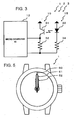
- the light-emitting portion 18 consists of the light-emitting diode 33 and a current-limiting resistor 34, for example.
- the light-receiving portion 19 consists of the phototransistor 31 and a resistor 32 for adjusting the light reception sensitivity.
- the hour wheel 25 has the fundamental reflective surface 26 at the position of just 12 o'clock.
- it has the reflective surfaces 27, 28, and 29 at positions which are shifted from the fundamental reflective surface 26 by 30 degrees, 90 degrees, and 210 degrees, respectively, clockwise C1. That is, the reflective surface 27 is at the position of 1 o'clock.
- the reflective surface 28 is at the position of 3 o'clock.
- the reflective surface 29 is at the position of 7 o'clock.
- the angular interval A1 between the reflective surfaces 26 and 27 is 30 degrees.
- the angular interval A2 between the reflective surfaces 27 and 28 is 60 degrees.
- the angular interval A3 between the reflective surfaces 28 and 29 is 120 degrees.
- the angular interval A4 between the reflective surfaces 29 and 26 is 150 degrees.
- the intervals A1, A2, A3, and A4 are different in size.
- the dial not shown
- hands are present under the figure.
- the light from the light-emitting portion 18 is reflected by the reflective surface 27, 28, or 29 and received by the light-receiving portion 19 in cases where the hour wheel 25 is in the rotational position of just 1 o'clock (i.e., the reflective surface 27 is located at the reflective position K), the hour wheel is in the rotational position of just 3 o'clock (i.e., the reflective surface 28 is located at the reflective position K), or the hour wheel is in the rotational position of just 7 o'clock (i.e., the reflective surface 29 is located at the reflective position K), as well as in the case where the hour wheel 25 is in the rotational position of just 12 o'clock (i.e., the fundamental reflective surface 26 is at the reflective position K that is just located on the incident light path Li).
- the second wheel 23 and minute wheel 24 are located at the initial positions Si1 and Si2, respectively, and so it is assured that the light paths Li and Lr are opened.
- an initial position detection program 50 functioning to detect the initial positions using the hand position setting device 2 provided with the hand position detecting device 3 of a preferred embodiment of the invention constructed as described so far.
- the processing described in the flowchart is carried out by executing the initial position detection program 50 by means of the CPU 13, the program being loaded in the memory 14.
- the contents of the hand wheel relative position data storage portion 53 are reset to zero, for example. If desired, the contents in this reset state may be saved to other storage region such that the state taken during resetting can be reproduced.
- the light-emitting device 33 of the light-emitting portion 18 and light-receiving device 31 of the light-receiving portion 19 are started to be electrically fed and driven. Emission of the beam Bi from the light-emitting device 33 of the light-emitting portion 18 begins (step S101 of Fig. 4).
- the watch 1 enters the forced reset mode.
- the repetition frequency of the pulses P2 from the frequency divider circuit 11 of Fig. 1 is increased, for example, by a factor of many tens or pulses having repetition frequencies of more than many tens of Hz of the original output from the frequency divider circuit 11 are adopted to drive the motor.
- the second hand 60 is forcedly rotated at a high speed of about 1 rotation/second or higher (step S102).
- step S102 When rotation of the hands 60, 61, and 62 is started in this forced reset mode, the contents of the hand wheel relative position data storage portion 53 have been reset.
- subsequent positions of the hands 60, 61, and 62 correspond to the counted values in the hand wheel relative position data storage portion 53 in a 1:1 relation, it being noted that the position assumed at the moment when a forced resetting operation was started is taken as the initial position (origin).
- the motor 16 is rotated one step via the driver circuit 15 (step S102 of Fig. 4).
- the second wheel 23 of the wheel train 17 rotates an amount corresponding to 1 second.
- the minute wheel 24 coupled to the second wheel 23 via the wheel train and the hour wheel 25 coupled to the minute wheel 24 via the wheel train rotate amounts corresponding to 1 second.
- step S103 Under the state in which the hand wheels 23, 24, and 25 of the wheel train 17 have rotated amounts corresponding to 1 second in this way, a check is performed as to whether the light-receiving portion 19 has received the reflected light Br which has been emitted from the light-emitting portion 18 and reflected by a reflective surface (step S103).
- step S102 the program goes back to step S102, where the motor 16 is again rotationally driven one step forwardly.
- step S103 a check is made as to whether the light-receiving portion 19 has detected the reflected light Br.
- This driving of the motor 16 for forward rotation (step S102) and the check performed by the light-receiving portion 19 as to whether detection of light is done or not (step S103) are repeatedly carried out until the light-receiving portion 19 detects the reflected light Br from any one of the reflective surfaces 26, 27, 28, and 29.
- the hour wheel 25 reaches the rotational position of just 0 (12) o'clock, just 1 o'clock, just 3 o'clock, or just 7 o'clock (i.e., any one of the reflective surfaces 26, 27, 28, and 29 is located at the reflective position K that should be the intersection of the incident light path Li and reflected light path Lr)
- the light Bi coming out of the light-emitting portion 18 passes through the incident light path Li, reaches the reflective surface 26, 27, 28, or 29, is reflected by the reflective surface 26, 27, 28, or 29, and forms the reflected light Br that passes through the reflected light path Lr.
- This reflective surface interval counter 54 counts the relative amount of rotation R of the motor 16 rotationally driven after detection of any one of the reflective surfaces 26, 27, 28, and 29 at an accuracy of 1 second, the relative amount of rotation R being expressed in terms of time or in hours. Then, the motor 16 is driven forward at high speed until the counted value of the reflective surface interval counter 54 reaches 1 hour (e.g., 3, 600) (steps S105 and S106).
- step S107 When rotational driving corresponding to 1 hour is completed, the light-emitting device 33 of the light-emitting portion 18 and the light-receiving device 31 of the light-receiving portion 19 are again driven (step S107). A check is made as to whether the light Br from the light-emitting portion 18 is received by the light-receiving portion 19 (step S108).
- steps S105 to S108 whenever the motor 16 is rotationally driven an amount corresponding to 1 hour, the light-emitting device 33 and light-receiving device 31 are driven, and it is checked whether the light Br from the light-emitting device 18 is received by the light-receiving portion 19 (whether any one of the reflective surfaces 26, 27, 28, and 29 has reached the reflective position K that is the intersection of the incident light path Li and reflected light path Lr). During this interval, the reflective surface interval counter 54 counts how many hours for which the motor 16 has been rotated.
- step S108 After the first 1-hour rotational driving, when the program first reaches the step S108, if the light-receiving portion 19 detects the light Br, the program exits from the step S108 with YES and stops the light-emitting device 33 and light-receiving device 31 from being driven (step S109). Then, the program enters step S110, where the contents of the reflective surface interval counter 54 are shown to be 1 hour. Since 1 hour has passed since the first detection, the program exits from the step S110 with YES. The reflective surfaces located at intervals of 1 hour are only the reflective surface 26 located at the position of just 12 o'clock and the reflective surface 27 located at the position of just 1 o'clock. Therefore, it can be seen that the reflective surface 27 produces the second reflection at this moment. Accordingly, in step S113, the motor 16 is reversely driven an amount corresponding to 1 hour to return the hour wheel 25 to the position of just 12 o'clock (step S114). Thus, positional resetting to the initial positions is completed.
- step S115 if the light Br is not detected by the light-receiving portion 19 on reaching step S108, a check is performed as to whether the time elapsed since the first detection has reached 4 hours by referring to the contents of the reflective surface interval counter 54 (step S115).
- step S105 and S106 the motor 16 is rotationally driven an amount corresponding to 1 hour.
- step S105 and S106 the light-receiving device 31 and light-emitting device 33 are driven, and a check is performed as to whether the light is received by the light-receiving portion 19 (step S108).
- step S109 the step S110, where it is found from the contents of the reflective surface interval counter 54 that 2 hours have passed since the first detection. Therefore, skip the step S110 with NO, enter step S111, and skip the step S110 with YES. Since the reflective surfaces located at intervals of 2 hours are only the reflective surface 27 at the position of just 1 o'clock and the reflective surface 28 at the position of just 3 o'clock, it is seen that the reflective surface 28 located at the position of just 3 o'clock produces the second reflection at this moment. Accordingly, in step S114, the motor 16 is rearwardly driven an amount corresponding to 3 hours, and the hour wheel 25 is returned to the position of just 12 o'clock. Thus, positional resetting to the initial positions is completed.
- step S115 After it is rotationally driven an amount corresponding to 2 hours after the first detection, if the light Br is not detected by the light-receiving portion 19 on reaching the step S108, a check is performed as to whether the amount of rotational driving after the first detection has reached an amount corresponding to 4 hours (step S115).
- the program exits from the step S115 with NO and returns to the step S104, where the light-receiving device 31 and light-emitting device 33 are once stopped from being driven.
- step S105 and S106 the motor 16 is further rotationally driven an amount corresponding to 1 hour.
- the light-emitting device 33 and light-receiving device 31 are driven, and a check is performed as to whether the light is received by the light-receiving portion 19 (step S108).
- step S108 Since it is unlikely that the light Br is detected by the light-receiving portion 19 after 3 hours from the first detection, skip the step S108 with NO and enter the step S115. Furthermore, skip the step S115 with NO and again return to the step S104, stop the light-receiving device 31 and light-emitting device 33 once from being driven.
- the motor 16 is further rotationally driven an amount corresponding to 1 hour (steps S105 and S106).
- the light-emitting device 33 and light-receiving device 31 are driven, and a check is performed as to whether the light is received by the light-receiving portion 19 (step S108).
- the contents of the reflective surface interval counter 54 are 4 hours.
- step S108 the light-emitting device 33 and light-receiving device 31 stop from being driven (step S109) and enter the step S110, where 4 hours have passed since the first detection. Therefore, skip the step S110 with NO and then skip step S111 with NO. Since the reflective surfaces located at intervals of 4 hours are only the reflective surface 28 located at the position of just 3 o'clock and the reflective surface 29 located at the position of just 7 o'clock, it can be seen that the reflective surface 29 in the position of the just 7 o'clock produces the second reflection at this instant. Accordingly, in step S112, the motor 16 is forwardly driven an amount corresponding to 5 hours, and the hour wheel 25 is moved into the position of just 12 o'clock. Thus, positional resetting to the initial positions is completed.
- step S115 where the light Br is not detected by the light-receiving portion 19, it follows that the light-receiving portion 19 detects nothing even after the motor is rotationally driven for 4 hours after the first detection. Therefore, skip the step S115 with YES, and the light-receiving device 31 and light-emitting device 33 stop from being driven (step S116).
- the motor is located at a position rotated from the position of just 7 o'clock by an amount corresponding to 4 hours, i.e., at the position of just 11 o'clock, at this instant. Therefore, the motor 16 is further rotationally driven an amount corresponding to 1 hour from the position of this just 11 o'clock (step S117).
- the hour wheel 25 is moved into the position of just 12 o'clock.
- the motor is rotationally driven an average amount corresponding to 2.5 hours to detect the reflective surface 26. Then, the motor is rotationally driven an amount corresponding to 1 hour to detect the second reflective surface 27. Therefore, the motor is rotationally driven an average amount corresponding to 3.5 hours as a whole.
- the motor is rotationally driven an average amount corresponding to 0.5 hour to detect the reflective surface 27. Then, the motor is rotationally driven an amount corresponding to 2 hours to detect the second reflective surface 28. Therefore, the motor is rotationally driven an average amount corresponding to 2.5 hours as a whole.
- the motor is rotationally driven an average amount corresponding to 1 hour to detect the reflective surface 28. Then, the motor is rotationally driven an amount corresponding to 4 hours to detect the second reflective surface 29. It follows that the motor is rotationally driven an average amount corresponding to 5 hours as a whole.
- the motor is rotationally driven an average amount corresponding to 2 hours to detect the reflective surface 29. Then, the motor is rotationally driven an amount corresponding to 4 hours to detect that the second reflective surface 26 is not reached. Consequently, the motor is rotationally driven an average amount corresponding to 6 hours as a whole.
- this watch 1 is provided with the plural reflective surfaces 26, 27, 28, and 29 which are spaced from each other by different angular intervals A1, A2, A3, and A4. Therefore, it is possible to determine where the initial position is present simply by rotating the hour wheel 25 about one half turn at maximum. Consequently, the initial position can be determined quickly. Furthermore, in this watch 1, the reflective surfaces are at positions on the hour. Therefore, after the first reflective surface is detected, the initial position can be determined simply by driving the light-emitting device 33 and light-receiving device 31 for a short time whenever the amount of rotation of the hour wheel 25 becomes an integral multiple of an amount corresponding to 1 hour. In consequence, the energy consumption can be suppressed to a minimum.
- the reflective surface 29 may be placed at the position of just 7 o'clock, for example.
- the angular interval A3 is 90 degrees (corresponding to 3 hours).
- the angular interval A4 is 180 degrees (corresponding to 6 hours).
- rotation corresponding to 3 hours suffices. That is, in step S115 of Fig. 4, a decision or evaluation is made in 3 hours instead of 4 hours.
- the condition is limited to the condition where reflection on the hour is detected, it is impossible to place five or more reflective surfaces that are unequally spaced from each other.
- three reflective surfaces may be placed at unequal angular intervals if desired. For example, a combination of just 12 o'clock, just 1 o'clock, and just 3 o'clock (for simplicity of illustration, this is given by (0, 1, 3) here) may be possible. Also, (0, 1, 4), (0, 1, 5), (0, 1, 6), (0, 2, 5), (0, 2, 6), or (0, 3, 7) may be possible.
- the rotational position is ascertained after 4 hours from the first reception and detection of the light. Therefore, the hands can be moved from the ascertained rotational positions to arbitrary given positions. Accordingly, in the description of the embodiment described so far, it has been assumed that the reflective surface 26 is at the position of just 12 o'clock. As long as the reflective surfaces 26, 27, 28, and 29 are at positions on the hour (i.e., when the hour wheel is at a position on the hour, the reflective surfaces 26, 27, 28, and 29 supply the light Bi from the light-emitting device 18 as the reflected light Br to the light-receiving portion 19) , the reflective surface 26 does not need to be at a position of just 12 o'clock.
- the hour wheel 25 may be at a position not on the hour.
- step S102 information about the amount of rotation of the driven motor in step S102 before the rotational position where the first reflection is obtained is reached is not used.
- the motor is rotated an amount corresponding to more than 4 hours based on the counted value of the hand wheel relative position data storage portion 53 and a reflective surface is first detected (in a case where the counted value exceeds 4 hours), for example, arrival at the reflective surface 26 is ascertained unconditionally.
- a reflective surface is first detected after the motor is rotated an amount corresponding to more than 2 hours, it is ascertained that the reflective surface 26 or 29 has been reached.
- the rotational position of the hour wheel 25 may be ascertained with a smaller amount of rotation for driving by making use of information about the amount of rotation given to the motor in step S102 until the rotational position where the first reflection is obtained is reached.
- the average time for which the light-emitting device 33 and light-receiving device 31 are driven is substantially dependent on the amount of driving necessary to detect the first reflective surface and, therefore, approximately the same in practice.
- the light-emitting device 33 and light-receiving device 31 are placed at an interval of D.
- the light Bi from the light-emitting device 33 obliquely hits the reflective surface 26 or the like through the apertures 23i and 24i for passage of incident light.
- the reflected light Br produced by oblique reflection from the reflective surface 26 or the like is received by the light-receiving device 31 via the apertures 23r and 24r for passage of reflected light. That is, an example of oblique incidence and oblique reflection has been described. Instead, the structure may be constructed as shown in Figs. 6.
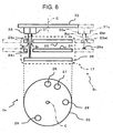
- the light-emitting device 33 and light-receiving device 31 are placed close to each other such that they can be placed substantially just opposite to the reflective surface 26 or the like.
- the second wheel 23 has the shared aperture 23c acting as the aperture for passage of incident light and as the aperture for passage of reflected light.
- the minute wheel 24 similarly has the shared aperture 24c acting also as the aperture for passage of incident light and as the aperture for passage of reflected light.
- the light Bi from the light-emitting device 33 passes through the shared apertures 23c and 24c acting as the aperture for passage of incident light and substantially perpendicularly hits the reflective surfaces 26, 27, 28, 29, etc. on the hour wheel 25.
- the reflected light Br produced by substantially perpendicular reflection at the reflective surfaces 26, 27, 28, 29, and so on passes through the shared apertures 23c and 24c acting also as the aperture for passage of reflected light and is received by the light-receiving device 31 located close to the light-emitting device 33.
- this hand position detecting device 3a is configured substantially similarly to the hand position detecting device 3 in other respects.
- the regions of the hour wheel 25 permitting light detection are the reflective surfaces on the hour wheel 25.
- the regions of the hour wheel 25 permitting light detection may be light transmissive regions as shown in Figs. 7 instead of reflective surfaces.
- the hour wheel 25 has apertures 26h, 27h, 28h, and 29h acting as light transmissive regions in the same positions as the reflective surfaces 26, 27, 28, and 29 instead of these reflective surfaces 26, 27, 28, and 29.
- the device has a circuit board 22d for detection.
- the light-receiving device 31 is mounted on the circuit board 22d on the opposite side of the wheel train 17 from the circuit board 22.
- this hand position detecting device 3b in a case where the second wheel 23, minute wheel 24, and hour wheel 25 are in the initial positions Si1, Si2, Si3, etc., the light Bi from the light-emitting device 33 passes through the apertures 23i and 24i in the second wheel 23 and minute wheel 24 for passage of incident light and through the apertures 26h, 27h, 28h, 29h, etc. in the hour wheel 25, and is received by the light-receiving device 31 that is placed just opposite to the light-emitting device 33 on the circuit board 22d on the rear side of the hour wheel 25.
- This hand position detecting device 3a differs from the hand position detecting device 3a of Figs.
- the hand position detecting device 3a is constructed substantially similarly to the hand position detecting device 3a of Figs. 6 in other respects.
- all the hand wheels are rotated by one motor via wheel trains.
- the wheel trains may be rotated by plural motors.
- an additional set of light-emitting device 33a and light-receiving device 31a may be provided at a different distance from the center of rotation C on the circuit board 22 as indicated by the imaginary lines.
- another shared aperture 23ac capable of acting as the aperture for passage of incident light and as the aperture for passage of reflected light may be formed in the second wheel 23 at a given angular position and at a radial position where the incident light Bai and reflected light Bar between the light-emitting device 33a and light-receiving device 31a can be passed.
- reflective surfaces 26a and so on similar to the reflective surfaces 26, 27, 28, and 29 of the hour wheel 25 may be formed on the minute wheel 24 at desired angular intervals at given angular positions and at radial positions where the surfaces can be placed just opposite to the shared aperture 23ac.
- the second wheel 23 acts as the first hand wheel while the minute wheel 24 acts as the second hand wheel in relation to the light-emitting device 33a and light-receiving device 31a. Accordingly, in the above-described embodiment, if the light-receiving device 31a detects that the second wheel 23 and minute wheel 24 have arrived at given reference positions in relation to the light-emitting device 33a and light-receiving device 31a in the same way as in the case where the light-receiving device 31 detects that the minute wheel 24 acting as the first hand wheel and the hour wheel 25 acting as the second hand wheel have arrived at given angular positions in relation to the light-emitting device 33 and light-receiving device 31, then the positions of the second wheel 23 and minute wheel 24 can be detected in a short time from the amount of rotation or the like occurring until the next given reference positions for the second wheel 23 and minute wheel are detected by rotating the second wheel 23 at high speed.
- the position on the hour for example, can be identified in a short time.
- the position of the hour wheel 25 can be identified at high speed in relation to the light-emitting device 33 and light-receiving device 31.
- the second wheel 23 does not need to be associated with the set of light-emitting device and light-receiving device 33, 31.
- the radius of the second wheel 23 may be smaller than the radii of the other wheels 24 and 25.
- the second wheel 23 or a wheel corresponding to it may not be concentric with the minute wheel 24 or hour wheel 25.
Landscapes
- Physics & Mathematics (AREA)
- General Physics & Mathematics (AREA)
- Electromechanical Clocks (AREA)
Abstract
Description
Claims (12)
- A hand position detecting device comprising:wherein the second hand wheel has the plural regions (26-29) permitting light detection, the regions being angularly unequally spaced from each other such that the light-receiving device receives the light made detectable when the second hand wheel is at plural intermediate rotational positions other than the given positions.a first hand wheel (24);a second hand wheel (25) which is rotated in response to rotation of the first hand wheel so as to make one rotation as the first hand wheel makes an integral number of rotations;a light-emitting device (33) which is made to hit regions formed in the second hand wheel permitting light detection via an aperture (24i) formed in the first hand wheel to pass incident light, when the first hand wheel and the second hand wheel have reached given positions;a light-receiving device (31) to detect light made detectable from the region permitting light detection;
- A hand position detecting device set forth in claim 1, wherein the regions of the second hand wheel permitting light detection are reflective surfaces and the light made detectable is reflected light, and wherein the light-receiving device detects the reflected light reflected by the reflective surfaces via the aperture in the first hand wheel to pass reflected light.
- A hand position detecting device set forth in claim 2, wherein when the.first and the second hand wheels have reached the given positions, the light from the light-emitting device is made to obliquely hit the reflective surfaces on the second hand wheel via the aperture in the first hand wheel to pass incident light, and wherein reflected light reflected by the reflective surfaces obliquely is detected by the light-receiving device via the aperture in the first hand wheel to pass reflected light.
- A hand position detecting device set forth in claim 2, wherein the aperture to pass incident light and the aperture to pass reflected light consist of a common shared aperture, when the first and the second hand wheels have reached the given positions, the light from the light-emitting device is made to hit the reflective surfaces on the second hand wheel substantially perpendicularly via the shared aperture in the first hand wheel, the shared aperture acting as the aperture to pass incident light, and reflected light reflected substantially perpendicularly at the reflective surfaces is detected by the light-receiving device via the shared aperture acting as the aperture in the first hand wheel to pass reflected light.
- A hand position detecting device set forth in claim 1, wherein the regions of the second hand wheel permitting light detection are light transmissive regions, the light made detectable is a transmitted hole passed through the light transmissive regions of the second hand wheel, and the light-receiving device detects the transmitted hole from the light transmissive regions.
- A hand position detecting device set forth in claim 1, wherein the angular interval between the regions of the second hand wheel permitting detection is an integral multiple of an incremental rotation angle through which the second hand wheel rotates when the first hand wheel is rotated once.
- A hand position detecting device set forth in claim 1, wherein the first hand wheel is a minute wheel, while the second hand wheel is an hour wheel.
- A hand position detecting device set forth in claim 7, wherein the angular interval between the regions of the hour wheel permitting detection is an integral multiple of 30 degrees.
- A hand position detecting device set forth in claim 7, wherein the hour wheel has four regions permitting detection including a reference position at which incident light from the light-emitting device is supplied as the light made detectable to the light-receiving device when the hour wheel is at a given position, the four regions being arranged in the direction of rotation, and wherein the angular intervals between adjacent regions of the four regions permitting detection are 30 degrees, 60 degrees, 120 degrees, and 150 degrees.
- A hand position detecting device set forth in claim 7, wherein the hour wheel has four regions permitting detection including a reference position at which incident light from the light-emitting device is supplied as the light made detectable to the light-receiving device when the hour wheel is at a given position, the four regions being arranged in the direction of rotation, and wherein the angular intervals between adjacent reflective surfaces of the four regions permitting detection are 30 degrees, 60 degrees, 90 degrees, and 180 degrees.
- A hand position detecting device set forth in claim 7, wherein after a first one of the regions permitting detection is detected by rotation of the hour wheel, the light-emitting device and the light-receiving device are once stopped from being driven, and wherein each time the hour wheel rotates for an hour, the light-emitting device and the light-receiving device are driven during a time taken to detect whether the light from the light-emitting device is received by the light-receiving device or not in the rotational position.
- An electronic timepiece comprising:wherein the hand position detecting device comprises a first hand wheel (24), a second hand wheel (25) which is rotated in response to rotation of the first hand wheel so as to make one rotation as the first hand wheel makes an integral number of rotations, a light-emitting device (33) which is made to hit regions formed in the second hand wheel permitting light detection via an aperture (24i) formed in the first hand wheel to pass incident light, when the first hand wheel and the second hand wheel reached given positions, a light-receiving device (31) to detect light made detectable from the regions permitting light detection, wherein the second hand wheel has plural regions (26-29) permitting light detection, the regions being angularly unequally spaced from each other such that the light-receiving device receives the light made detectable when the second hand wheel is at plural intermediate rotational positions other than the given positions.a hand position detecting device;
Applications Claiming Priority (4)
| Application Number | Priority Date | Filing Date | Title |
|---|---|---|---|
| JP2002338292 | 2002-11-21 | ||
| JP2002338292 | 2002-11-21 | ||
| JP2003375389A JP2004184404A (en) | 2002-11-21 | 2003-11-05 | Hand position detecting device and electronic timepiece provided with the same |
| JP2003375389 | 2003-11-05 |
Publications (2)
| Publication Number | Publication Date |
|---|---|
| EP1422581A2 true EP1422581A2 (en) | 2004-05-26 |
| EP1422581A3 EP1422581A3 (en) | 2005-07-13 |
Family
ID=32232730
Family Applications (1)
| Application Number | Title | Priority Date | Filing Date |
|---|---|---|---|
| EP03257333A Withdrawn EP1422581A3 (en) | 2002-11-21 | 2003-11-20 | Hand position detecting device and electronic timepiece provided therewith |
Country Status (3)
| Country | Link |
|---|---|
| US (1) | US20040120220A1 (en) |
| EP (1) | EP1422581A3 (en) |
| JP (1) | JP2004184404A (en) |
Cited By (2)
| Publication number | Priority date | Publication date | Assignee | Title |
|---|---|---|---|---|
| EP1607808A1 (en) * | 2004-06-15 | 2005-12-21 | Asulab S.A. | Method for the synchronization of the analog display of a timepiece provided with an electronic timebase |
| RU2824322C1 (en) * | 2023-09-08 | 2024-08-07 | Сергей Леонидович Беседин | Self-aligning electromechanical clock |
Families Citing this family (11)
| Publication number | Priority date | Publication date | Assignee | Title |
|---|---|---|---|---|
| JP2004184405A (en) * | 2002-11-21 | 2004-07-02 | Seiko Instruments Inc | Hand position detecting device and electronic timepiece using the same |
| US8023362B2 (en) | 2007-09-28 | 2011-09-20 | Casio Computer Co., Ltd. | Hand position detecting device and apparatus including the device |
| JP4596002B2 (en) * | 2007-12-25 | 2010-12-08 | カシオ計算機株式会社 | Needle position detection device and needle position detection method |
| JP4623140B2 (en) * | 2008-05-28 | 2011-02-02 | カシオ計算機株式会社 | Needle position detection device and needle position detection control method |
| JP4730397B2 (en) * | 2008-05-30 | 2011-07-20 | カシオ計算機株式会社 | Needle position detector |
| EP2869140B1 (en) | 2013-10-30 | 2016-04-06 | The Swatch Group Research and Development Ltd. | Device for the detection of the position of timepiece hands |
| JP2016206057A (en) * | 2015-04-24 | 2016-12-08 | セイコーエプソン株式会社 | Electronic watch |
| JP6755714B2 (en) * | 2015-08-21 | 2020-09-16 | セイコーインスツル株式会社 | Movement and electronic clock |
| JP6546037B2 (en) * | 2015-08-21 | 2019-07-17 | セイコーインスツル株式会社 | Movement and electronic watch |
| US9971310B2 (en) * | 2015-08-21 | 2018-05-15 | Seiko Instruments Inc. | Movement and electronic timepiece |
| EP4202572B1 (en) * | 2021-12-22 | 2025-06-11 | Omega SA | Temperature control for a timepiece |
Family Cites Families (10)
| Publication number | Priority date | Publication date | Assignee | Title |
|---|---|---|---|---|
| DE4128752C2 (en) * | 1991-08-29 | 1997-12-04 | Junghans Uhren Gmbh | Position detection and correction device |
| DE4446929C2 (en) * | 1994-12-09 | 2002-05-23 | Fritz Schaeffel | Clock, in particular radio clock |
| DE19524030C1 (en) * | 1995-07-01 | 1996-11-14 | Haller Eckhart W Dipl Ing Fh | Display position detection device for stepping motor clock mechanism |
| JPH09166671A (en) * | 1995-09-28 | 1997-06-24 | Helmut Hechinger Gmbh & Co | Positioning device for clock hands |
| JP3328518B2 (en) * | 1996-11-06 | 2002-09-24 | セイコークロック株式会社 | Clock mechanical body |
| TW558677B (en) * | 2002-08-02 | 2003-10-21 | Chih-Hao Yiu | Device for detecting angular position |
| TW558676B (en) * | 2002-08-02 | 2003-10-21 | Chih-Hao Yiu | Device for detecting angular position |
| US20040125702A1 (en) * | 2002-10-21 | 2004-07-01 | Hideki Kitajima | Rotational position detection device, hand position detection device and clock using the hand position detection device |
| US6804173B2 (en) * | 2002-10-28 | 2004-10-12 | Chih Hao Yiu | Rotary members for timepiece having reflector sheets |
| JP2004184405A (en) * | 2002-11-21 | 2004-07-02 | Seiko Instruments Inc | Hand position detecting device and electronic timepiece using the same |
-
2003
- 2003-11-05 JP JP2003375389A patent/JP2004184404A/en active Pending
- 2003-11-20 US US10/718,115 patent/US20040120220A1/en not_active Abandoned
- 2003-11-20 EP EP03257333A patent/EP1422581A3/en not_active Withdrawn
Cited By (3)
| Publication number | Priority date | Publication date | Assignee | Title |
|---|---|---|---|---|
| EP1607808A1 (en) * | 2004-06-15 | 2005-12-21 | Asulab S.A. | Method for the synchronization of the analog display of a timepiece provided with an electronic timebase |
| US7218577B2 (en) | 2004-06-15 | 2007-05-15 | Asulab, S.A. | Method for synchronising an analog display of a timepiece with its electronic time base |
| RU2824322C1 (en) * | 2023-09-08 | 2024-08-07 | Сергей Леонидович Беседин | Self-aligning electromechanical clock |
Also Published As
| Publication number | Publication date |
|---|---|
| JP2004184404A (en) | 2004-07-02 |
| US20040120220A1 (en) | 2004-06-24 |
| EP1422581A3 (en) | 2005-07-13 |
Similar Documents
| Publication | Publication Date | Title |
|---|---|---|
| US20040120220A1 (en) | Hand position detecting device and electronic timepiece provided therewith | |
| US5999495A (en) | Timepiece movement | |
| US8023364B2 (en) | Hand position detecting device and hand position control method | |
| US4420263A (en) | Electronic watch with means for detecting the movement of a hand through a reference position | |
| JP4650472B2 (en) | Needle position detector | |
| US6807128B2 (en) | Position detecting and correcting device for timepiece | |
| CN1987518A (en) | Distance measuring method and distance measuring device | |
| JPH09166671A (en) | Positioning device for clock hands | |
| US6731571B2 (en) | Position detecting and correcting device for timepiece | |
| JP3514644B2 (en) | Auto correct clock | |
| JP2006046924A (en) | Rotational position detecting mechanism and clocking device | |
| JP2004184405A (en) | Hand position detecting device and electronic timepiece using the same | |
| JP2002071847A (en) | Automatic correction clock | |
| JPH089676Y2 (en) | Control device for analog clock of time recorder | |
| JP3499455B2 (en) | Clock hand position detector | |
| KR20000035636A (en) | Automatic correctable timepiece | |
| JP2002071846A (en) | Automatic correction clock | |
| JP2500514B2 (en) | Rotating body position detector | |
| JP4542750B2 (en) | Analog radio wave correction clock and display method of analog radio wave correction clock | |
| JP3643278B2 (en) | Hand position detection method and hand position correction device for radio wave correction watch | |
| JP3673432B2 (en) | Self-correcting clock | |
| JP2002257956A (en) | Analog radio-controlled watch | |
| JP3101917U (en) | Clock operating mechanism | |
| JP2001042060A (en) | Movement for automatic correction clock | |
| US20040085860A1 (en) | Position detecting and correcting device for timepiece |
Legal Events
| Date | Code | Title | Description |
|---|---|---|---|
| PUAI | Public reference made under article 153(3) epc to a published international application that has entered the european phase |
Free format text: ORIGINAL CODE: 0009012 |
|
| AK | Designated contracting states |
Kind code of ref document: A2 Designated state(s): AT BE BG CH CY CZ DE DK EE ES FI FR GB GR HU IE IT LI LU MC NL PT RO SE SI SK TR |
|
| AX | Request for extension of the european patent |
Extension state: AL LT LV MK |
|
| PUAL | Search report despatched |
Free format text: ORIGINAL CODE: 0009013 |
|
| AK | Designated contracting states |
Kind code of ref document: A3 Designated state(s): AT BE BG CH CY CZ DE DK EE ES FI FR GB GR HU IE IT LI LU MC NL PT RO SE SI SK TR |
|
| AX | Request for extension of the european patent |
Extension state: AL LT LV MK |
|
| AKX | Designation fees paid | ||
| REG | Reference to a national code |
Ref country code: DE Ref legal event code: 8566 |
|
| STAA | Information on the status of an ep patent application or granted ep patent |
Free format text: STATUS: THE APPLICATION IS DEEMED TO BE WITHDRAWN |
|
| 18D | Application deemed to be withdrawn |
Effective date: 20060114 |