EP1422529A1 - Airborne microwave/infrared wind shear and clear air turbulence detector - Google Patents
Airborne microwave/infrared wind shear and clear air turbulence detector Download PDFInfo
- Publication number
- EP1422529A1 EP1422529A1 EP03026296A EP03026296A EP1422529A1 EP 1422529 A1 EP1422529 A1 EP 1422529A1 EP 03026296 A EP03026296 A EP 03026296A EP 03026296 A EP03026296 A EP 03026296A EP 1422529 A1 EP1422529 A1 EP 1422529A1
- Authority
- EP
- European Patent Office
- Prior art keywords
- aircraft
- air
- image
- disturbance
- recited
- Prior art date
- Legal status (The legal status is an assumption and is not a legal conclusion. Google has not performed a legal analysis and makes no representation as to the accuracy of the status listed.)
- Ceased
Links
- 238000012544 monitoring process Methods 0.000 claims abstract description 3
- 238000000034 method Methods 0.000 claims description 10
- 238000010438 heat treatment Methods 0.000 claims description 2
- 238000001514 detection method Methods 0.000 description 2
- 238000012986 modification Methods 0.000 description 2
- 230000004048 modification Effects 0.000 description 2
- 230000000694 effects Effects 0.000 description 1
- 238000003384 imaging method Methods 0.000 description 1
- 230000033001 locomotion Effects 0.000 description 1
- 230000000007 visual effect Effects 0.000 description 1
Images

Classifications
-
- G—PHYSICS
- G01—MEASURING; TESTING
- G01P—MEASURING LINEAR OR ANGULAR SPEED, ACCELERATION, DECELERATION, OR SHOCK; INDICATING PRESENCE, ABSENCE, OR DIRECTION, OF MOVEMENT
- G01P5/00—Measuring speed of fluids, e.g. of air stream; Measuring speed of bodies relative to fluids, e.g. of ship, of aircraft
- G01P5/10—Measuring speed of fluids, e.g. of air stream; Measuring speed of bodies relative to fluids, e.g. of ship, of aircraft by measuring thermal variables
-
- G—PHYSICS
- G01—MEASURING; TESTING
- G01P—MEASURING LINEAR OR ANGULAR SPEED, ACCELERATION, DECELERATION, OR SHOCK; INDICATING PRESENCE, ABSENCE, OR DIRECTION, OF MOVEMENT
- G01P13/00—Indicating or recording presence, absence, or direction, of movement
- G01P13/02—Indicating direction only, e.g. by weather vane
- G01P13/025—Indicating direction only, e.g. by weather vane indicating air data, i.e. flight variables of an aircraft, e.g. angle of attack, side slip, shear, yaw
-
- G—PHYSICS
- G01—MEASURING; TESTING
- G01P—MEASURING LINEAR OR ANGULAR SPEED, ACCELERATION, DECELERATION, OR SHOCK; INDICATING PRESENCE, ABSENCE, OR DIRECTION, OF MOVEMENT
- G01P5/00—Measuring speed of fluids, e.g. of air stream; Measuring speed of bodies relative to fluids, e.g. of ship, of aircraft
- G01P5/001—Full-field flow measurement, e.g. determining flow velocity and direction in a whole region at the same time, flow visualisation
Definitions
- the present invention relates generally to aircraft control systems, and more particularly, to an air disturbance detection system for an aircraft.
- Wind shear and clear air turbulence can lead to undesired motions in the aircraft.
- Wind shears are typically detected on the ground around airports. The information regarding wind shears is provided to pilots when approaching the airport.
- Turbulence is also an undesired effect on an aircraft. Turbulence may occur from following too closely to another aircraft. Such turbulence is typically avoided by spacing the aircraft take-offs and landings so that the turbulence has time to dissipate.
- other sources of turbulence particularly when airborne, may be present in the aircraft's path.
- wind shears may also be present in the aircraft path away from an airport or detection source.
- the present invention provides a system for detecting the presence of an air disturbance by imaging heated air in front of the aircraft.
- a method for monitoring an airborne disturbance in front of an airplane includes directing a high energy beam a distance in front of the airplane, heating the air with the beam, detecting an image of the heated air, and comparing the image to a profile to determine the presence of a disturbance.
- a system for detecting an air disturbance includes a high energy beam generator for generating a high energy beam in front of the aircraft.
- the system further includes an image detector for generating an image of the heated air in front of the aircraft.
- a controller is coupled to the image detector and compares the image to a profile to determine if the image resembles an air disturbance.
- One advantage of the invention is that more stable operation of the aircraft may be obtained.
- Another advantage of the invention is that by directing the high energy beam far enough in front of the aircraft, evasive maneuvers may be performed prior to the air disturbance.
- Figure 1 is a top view representing two microwave beams positioned in front of an aircraft.
- Figure 2 illustrates an aircraft having a heated air area with no disturbance in front of the aircraft.
- Figure 3 illustrates a heated area in front of an aircraft representing a wind shear.
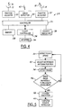
- Figure 4 is a block diagrammatic view of an air disturbance for an aircraft.
- Figure 5 is a flow chart of the operation of the system of Figure 4.
- an aircraft 10 having a first antenna 12 and a second antenna that each generate a respective beam 16, 18 to a point 20 in front of the aircraft.
- antenna are used other high energy beam generating sources may be used.
- Point 20 is spaced a predetermined distance d in front of the aircraft. As will be further described below, the distance d from aircraft 10 may vary based on the air speed of aircraft 10.
- each beam 16, 18 are focused at or near the same point 20.
- a region 22 in front of the aircraft having heated air is illustrated.
- the region closest to the aircraft and furthest away from point 20 is the coolest air and the region that is currently being heated at point 20 is correspondingly the hottest air. It should be noted that the heated air is actually the heated moisture within the air.
- region 22a that represents clear air. That is, region 22a has no air disturbance therein.
- the image of such an area from the plane's perspective is circular or nearly circular.
- region 22 when a disturbance is present, the shape of the region 22 is changed.
- region 22 has been changed to 22b and shows an indication of a wind shear. From the perspective of the aircraft, the wind shear takes on elliptical or a ribbon shape.
- Controller 26 is preferably microprocessor-based. Controller 26 may have memory 28 associated therewith. Memory 28, although illustrated as a separate component, may be incorporated as part of controller 26. Memory 28 may, for example, store images of air disturbances for comparison as will be further described below. Of course, the image may be processed digitally for comparison to a numerical threshold.
- Controller 26 is coupled to a pair of position adjusters 30, 32 that are coupled to antennas 12 and 14, respectively.
- Position adjusters 30 and 32 may, for example, be motorized devices.
- Position adjusters 30, 32 adjust the position of beams 16, 18 as will be further described below. By adjusting the positions of antennas 12, 14, position adjusters 30, 32 are able to move the intersection point of the beams closer or further away from the aircraft.
- Controller 26 may be coupled to a flight controller 34.
- Flight controller 34 is coupled to an air speed sensor 36.
- Air speed sensor or detector 36 provides information to the flight controller as to the air speed of the aircraft.
- Controller 26 receives this information from flight controller 34 and adjusts the position adjusters 30, 32 to adjust the position of high energy beam 16, 18.
- Flight controller 34 may also be used to control the aircraft to perform an avoidance maneuver so as to maneuver around any detected air disturbance. This will be further described below.
- Controller 26 may also be coupled to a cockpit indicator 38.
- Cockpit indicator 38 may provide a visual or audible indication to the flight crew as to the presence of turbulence above. If automatic control is not seized, the flight crew may be instructed to maneuver around the sensed disturbance. Both automated control and an indicator may be provided.
- Controller 26 is also coupled to an image detector 40.
- Image detector 40 in the present example is an infrared detector.
- the infrared image detector 40 is used to receive an image 42 of the air heated by the high energy beams in front of the aircraft.
- Image detector 40 may be located in various position on the aircraft including near the front of the fuselage.
- step 50 the aircraft speed is detected by a dedicated sensor or borrowing the data from another system.
- step 52 the microwave antenna positions are adjusted by the position adjusters above. The position of the intersection of the two high energy beams or microwave beams is preferably spaced a distance so that an evasive maneuver may be performed.
- step 54 an image is detected by the image detector 40.
- the image detector 40 generates an image signal that is compared to clear air versus other disturbances such as turbulence and wind shear. The comparison may be a profile of the actual images or numerical profile.
- step 56 if the image does not represent an air disturbance, the system repeats in step 50.
- step 56 if the image of the heated air represents an air disturbance, step 58 generates an indication to the flight crew as to the presence of a disturbance.
- step 60 an evasive maneuver may be performed. The performance of the evasive maneuver in step 60 may be performed manually or may be performed automatically by an automated flight controller.
- a microwave source is the most suitable for the present application.
- an evasive maneuver may be easily performed at a comfortable speed and pitch to maintain the ride quality for the passengers and crew.
Landscapes
- Engineering & Computer Science (AREA)
- Aviation & Aerospace Engineering (AREA)
- Physics & Mathematics (AREA)
- General Physics & Mathematics (AREA)
- Traffic Control Systems (AREA)
- Radar Systems Or Details Thereof (AREA)
Abstract
A system (24) for detecting an air disturbance in
front of an aircraft (10) has a controller (26) that is coupled
to an image detector (40). Image detector (40) generates an
image signal corresponding to heated air in front of the aircraft
(10). The air in front of the aircraft (10) is heated by
direct high energy beams such as microwave beams (16, 18) from
a respective microwave antenna (12, 14). By monitoring the
image, the presence of an air disturbance may be determined.
Position adjusters (30, 32) may be used to adjust the position
of the beams (16, 18) by controlling the position of antennas
(12, 14). The position of the beam is preferably maintained a
predetermined distance (d) in front of the aircraft (10) so
that an evasive maneuver may be performed.
Description
- The present invention relates generally to aircraft control systems, and more particularly, to an air disturbance detection system for an aircraft.
- For smooth aircraft operation, a smooth flow of air over the aircraft wings is desired. Wind shear and clear air turbulence can lead to undesired motions in the aircraft. Wind shears are typically detected on the ground around airports. The information regarding wind shears is provided to pilots when approaching the airport. Turbulence is also an undesired effect on an aircraft. Turbulence may occur from following too closely to another aircraft. Such turbulence is typically avoided by spacing the aircraft take-offs and landings so that the turbulence has time to dissipate. However, other sources of turbulence, particularly when airborne, may be present in the aircraft's path. Also, wind shears may also be present in the aircraft path away from an airport or detection source.
- Therefore, it would be desirable to provide a method for detecting the presence of air disturbances such as wind shears and clear air turbulence in front of an aircraft in time so that an evasive maneuver may be performed.
- The present invention provides a system for detecting the presence of an air disturbance by imaging heated air in front of the aircraft.
- In one aspect of the invention a method for monitoring an airborne disturbance in front of an airplane includes directing a high energy beam a distance in front of the airplane, heating the air with the beam, detecting an image of the heated air, and comparing the image to a profile to determine the presence of a disturbance.
- In a further aspect of the invention, a system for detecting an air disturbance includes a high energy beam generator for generating a high energy beam in front of the aircraft. The system further includes an image detector for generating an image of the heated air in front of the aircraft. A controller is coupled to the image detector and compares the image to a profile to determine if the image resembles an air disturbance.
- One advantage of the invention is that more stable operation of the aircraft may be obtained. Another advantage of the invention is that by directing the high energy beam far enough in front of the aircraft, evasive maneuvers may be performed prior to the air disturbance.
- Other aspects and advantages of the present invention will become apparent upon the following detailed description and appended claims, and upon reference to the accompanying drawings.
- Figure 1 is a top view representing two microwave beams positioned in front of an aircraft.
- Figure 2 illustrates an aircraft having a heated air area with no disturbance in front of the aircraft.
- Figure 3 illustrates a heated area in front of an aircraft representing a wind shear.
- Figure 4 is a block diagrammatic view of an air disturbance for an aircraft.
- Figure 5 is a flow chart of the operation of the system of Figure 4.
- In the following figures the same reference numerals will be used to identify the same components. While a specific embodiment of the present invention is illustrated, various modifications within the spirit of the invention would be evident to those skilled in the art.
- Referring now to Figure 1, an
aircraft 10 is illustrated having afirst antenna 12 and a second antenna that each generate arespective beam point 20 in front of the aircraft. Although antenna are used other high energy beam generating sources may be used.Point 20 is spaced a predetermined distance d in front of the aircraft. As will be further described below, the distance d fromaircraft 10 may vary based on the air speed ofaircraft 10. Preferably, eachbeam same point 20. - A
region 22 in front of the aircraft having heated air is illustrated. The region closest to the aircraft and furthest away frompoint 20 is the coolest air and the region that is currently being heated atpoint 20 is correspondingly the hottest air. It should be noted that the heated air is actually the heated moisture within the air. - Referring now to Figure 2,
aircraft 10 is shown positioned in front of aregion 22a that represents clear air. That is,region 22a has no air disturbance therein. The image of such an area from the plane's perspective is circular or nearly circular. - Referring now to Figure 3, when a disturbance is present, the shape of the
region 22 is changed. In this figure,region 22 has been changed to 22b and shows an indication of a wind shear. From the perspective of the aircraft, the wind shear takes on elliptical or a ribbon shape. - Referring now to Figure 4, a
system 24 for detecting an air disturbance in front of an aircraft is illustrated. The system includes acontroller 26.Controller 26 is preferably microprocessor-based.Controller 26 may havememory 28 associated therewith.Memory 28, although illustrated as a separate component, may be incorporated as part ofcontroller 26.Memory 28 may, for example, store images of air disturbances for comparison as will be further described below. Of course, the image may be processed digitally for comparison to a numerical threshold. -
Controller 26 is coupled to a pair ofposition adjusters 30, 32 that are coupled toantennas 12 and 14, respectively.Position adjusters 30 and 32 may, for example, be motorized devices.Position adjusters 30, 32 adjust the position ofbeams antennas 12, 14,position adjusters 30, 32 are able to move the intersection point of the beams closer or further away from the aircraft. -
Controller 26 may be coupled to aflight controller 34.Flight controller 34 is coupled to anair speed sensor 36. Air speed sensor ordetector 36 provides information to the flight controller as to the air speed of the aircraft.Controller 26 receives this information fromflight controller 34 and adjusts theposition adjusters 30, 32 to adjust the position ofhigh energy beam Flight controller 34 may also be used to control the aircraft to perform an avoidance maneuver so as to maneuver around any detected air disturbance. This will be further described below. -
Controller 26 may also be coupled to acockpit indicator 38.Cockpit indicator 38 may provide a visual or audible indication to the flight crew as to the presence of turbulence above. If automatic control is not seized, the flight crew may be instructed to maneuver around the sensed disturbance. Both automated control and an indicator may be provided. -
Controller 26 is also coupled to animage detector 40.Image detector 40 in the present example is an infrared detector. Theinfrared image detector 40 is used to receive animage 42 of the air heated by the high energy beams in front of the aircraft.Image detector 40 may be located in various position on the aircraft including near the front of the fuselage. - Referring now to Figure 5, a method for operating the
system 24 of Figure 4 is illustrated. Instep 50 the aircraft speed is detected by a dedicated sensor or borrowing the data from another system. Instep 52 the microwave antenna positions are adjusted by the position adjusters above. The position of the intersection of the two high energy beams or microwave beams is preferably spaced a distance so that an evasive maneuver may be performed. Instep 54 an image is detected by theimage detector 40. Theimage detector 40 generates an image signal that is compared to clear air versus other disturbances such as turbulence and wind shear. The comparison may be a profile of the actual images or numerical profile. Instep 56, if the image does not represent an air disturbance, the system repeats instep 50. Instep 56, if the image of the heated air represents an air disturbance,step 58 generates an indication to the flight crew as to the presence of a disturbance. Instep 60 an evasive maneuver may be performed. The performance of the evasive maneuver instep 60 may be performed manually or may be performed automatically by an automated flight controller. - As can be seen above, various types of energy sources may be provided. However, a microwave source is the most suitable for the present application. By providing adjustments for the high energy beam, an evasive maneuver may be easily performed at a comfortable speed and pitch to maintain the ride quality for the passengers and crew.
- While the invention has been described in connection with one or more embodiments, it should be understood that the invention is not limited to those embodiments. On the contrary, the invention is intended to cover all alternatives, modifications, and equivalents, as may be included within the spirit and scope of the appended claims.
Claims (10)
- A method for monitoring an airborne disturbance in front of an airplane (10) comprising:directing (52) a high energy beam (16, 18) a distance (d) in front of the airplane (10);heating the air with the beam (16, 18);detecting (54) an image (42) of heated air; andcomparing (56) the image (42) to a profile to determine the presence of a disturbance.
- A method as recited in claim 1, wherein directing (52) comprises directing a first beam (16) and a second beam (18) in front of the aircraft (10).
- A method as recited in claim 2, wherein directing (52) comprises focusing the first beam (16) and the second beam (18) to substantially a point (20).
- A method as recited in anyone of claims 1 to 3, wherein directing (52) comprises directing the high energy beam (16, 18) a distance (d) as a function of air speed of the airplane (10).
- A method as recited in anyone of claims 1 to 4, wherein directing (52) comprises directing a microwave beam (16, 18).
- A method as recited in anyone of claims 1 to 5, wherein comparing (56) comprises comparing the image (42) to a profile to determine the presence of a turbulence, and/or a wind shear.
- A method as recited in anyone of claims 1 to 6, wherein detecting (54) comprises infrared detecting.
- A system for detecting an air disturbance in front of an aircraft (10) comprising:a high energy beam generator (12, 14) generating a high energy beam (16, 18);an image detector (40) generating an image signal of heated air in front of the aircraft (10); anda controller (26) coupled to said image detector (40), said controller (26) comparing the image (42) to a profile to determine a disturbance.
- A system as recited in claim 8 wherein said image detector (40) comprises an infrared detector.
- A system as recited in claim 8 or 9 further comprising an indicator (38), said controller (26) controlling the indicator (38) in response to the disturbance.
Applications Claiming Priority (2)
| Application Number | Priority Date | Filing Date | Title |
|---|---|---|---|
| US301934 | 2002-11-22 | ||
| US10/301,934 US6828923B2 (en) | 2002-11-22 | 2002-11-22 | Airborne microwave/infrared wind shear and clear air turbulence detector |
Publications (1)
| Publication Number | Publication Date |
|---|---|
| EP1422529A1 true EP1422529A1 (en) | 2004-05-26 |
Family
ID=32229908
Family Applications (1)
| Application Number | Title | Priority Date | Filing Date |
|---|---|---|---|
| EP03026296A Ceased EP1422529A1 (en) | 2002-11-22 | 2003-11-15 | Airborne microwave/infrared wind shear and clear air turbulence detector |
Country Status (2)
| Country | Link |
|---|---|
| US (1) | US6828923B2 (en) |
| EP (1) | EP1422529A1 (en) |
Cited By (2)
| Publication number | Priority date | Publication date | Assignee | Title |
|---|---|---|---|---|
| GB2471952A (en) * | 2009-07-17 | 2011-01-19 | Boeing Co | Visual detection of clear air turbulence |
| EP2065711A3 (en) * | 2007-11-30 | 2011-12-28 | The Boeing Company | System and methods for detecting turbulence based upon observations of light scintillation |
Families Citing this family (32)
| Publication number | Priority date | Publication date | Assignee | Title |
|---|---|---|---|---|
| US8902100B1 (en) | 2008-03-07 | 2014-12-02 | Rockwell Collins, Inc. | System and method for turbulence detection |
| US7598901B2 (en) * | 2004-12-03 | 2009-10-06 | The Boeing Company | System for measuring turbulence remotely |
| FR2916280A1 (en) * | 2007-05-15 | 2008-11-21 | Thales Sa | RADAR SURVEILLANCE METHOD FOR WAKE TURBULENCE |
| WO2009002645A2 (en) | 2007-05-24 | 2008-12-31 | Aviation Communication & Surveillance Systems Llc | Systems and methods for aircraft winshear detection |
| US9057773B1 (en) | 2012-12-06 | 2015-06-16 | Rockwell Collins, Inc. | Weather information display system and method |
| US9244157B1 (en) | 2008-03-07 | 2016-01-26 | Rockwell Collins, Inc. | Weather radar threat depiction system and method |
| US9864055B1 (en) | 2014-03-12 | 2018-01-09 | Rockwell Collins, Inc. | Weather radar system and method for detecting a high altitude crystal cloud condition |
| US9244166B1 (en) | 2008-03-07 | 2016-01-26 | Rockwell Collins, Inc. | System and method for ice detection |
| US9244167B1 (en) | 2008-03-07 | 2016-01-26 | Rockwell Collins, Inc. | Long range weather information display system and method |
| US9846230B1 (en) | 2013-03-15 | 2017-12-19 | Rockwell Collins, Inc. | System and method for ice detection |
| DE102009050522B4 (en) * | 2009-10-23 | 2017-06-14 | Airbus Defence and Space GmbH | Localization system and method for finding thermals |
| US8629788B1 (en) * | 2010-08-10 | 2014-01-14 | Rockwell Collins, Inc. | Sensing, display, and dissemination of detected turbulence |
| US9223020B1 (en) | 2010-09-28 | 2015-12-29 | Rockwell Collins, Inc. | System and method for weather detection using more than one source of radar data |
| US20120101747A1 (en) * | 2010-10-25 | 2012-04-26 | University Of Louisville Research Foundation, Inc. | Detection and imaging of turbulence in a fluid |
| US8666570B1 (en) * | 2010-11-19 | 2014-03-04 | The Boeing Company | Volcanic ash detection by optical backscatter using standard aircraft lights |
| US8913124B2 (en) * | 2011-02-03 | 2014-12-16 | The United States Of America As Represented By The Administrator Of The National Aeronautics And Space Administration | Lock-in imaging system for detecting disturbances in fluid |
| US8660714B2 (en) * | 2011-02-22 | 2014-02-25 | Honeywell International Inc. | Aircraft systems and methods for providing exhaust warnings |
| US9019146B1 (en) | 2011-09-27 | 2015-04-28 | Rockwell Collins, Inc. | Aviation display depiction of weather threats |
| US9823347B1 (en) | 2014-03-12 | 2017-11-21 | Rockwell Collins, Inc. | Weather radar system and method for high altitude crystal warning interface |
| US9116244B1 (en) | 2013-02-28 | 2015-08-25 | Rockwell Collins, Inc. | System for and method of weather phenomenon detection using multiple beams |
| US10701287B1 (en) * | 2013-05-23 | 2020-06-30 | Rockwell Collins, Inc. | Passive clear air turbulence detection system and method |
| US9612333B2 (en) | 2013-10-04 | 2017-04-04 | Erik Jason Bauman | System for sharing atmospheric data |
| US9535158B1 (en) | 2013-11-21 | 2017-01-03 | Rockwell Collins, Inc. | Weather radar system and method with fusion of multiple weather information sources |
| US9599707B1 (en) | 2014-01-23 | 2017-03-21 | Rockwell Collins, Inc. | Weather radar system and method with path attenuation shadowing |
| US9810770B1 (en) | 2014-07-03 | 2017-11-07 | Rockwell Collins, Inc. | Efficient retrieval of aviation data and weather over low bandwidth links |
| US9869766B1 (en) | 2015-01-28 | 2018-01-16 | Rockwell Collins, Inc. | Enhancement of airborne weather radar performance using external weather data |
| US10809375B1 (en) | 2015-09-14 | 2020-10-20 | Rockwell Collins, Inc. | Radar system and method for detecting hazards associated with particles or bodies |
| US10302815B1 (en) | 2015-10-01 | 2019-05-28 | Rockwell Collins, Inc. | System and method of integrating global convective weather |
| US10494108B1 (en) | 2016-05-17 | 2019-12-03 | Rockwell Collins, Inc. | System and method for providing icing condition warnings |
| US11430344B2 (en) | 2018-07-09 | 2022-08-30 | The Boeing Company | Aircraft position-based air turbulence detection systems and methods |
| CN116039959B (en) * | 2023-02-13 | 2023-08-15 | 北京控制工程研究所 | Method and device for controlling evasive maneuver of space vehicle |
| US12523775B2 (en) * | 2023-10-27 | 2026-01-13 | The Boeing Company | Aircraft acceleration prediction using lidar trained artificial intelligence |
Citations (3)
| Publication number | Priority date | Publication date | Assignee | Title |
|---|---|---|---|---|
| US3182499A (en) * | 1962-12-28 | 1965-05-11 | Moses Harry | Method of measuring wind velocity |
| US3448613A (en) * | 1966-09-16 | 1969-06-10 | Jacob Kastner | System for tracking air currents |
| US5523759A (en) * | 1992-04-14 | 1996-06-04 | Honeywell Inc. | In flight doppler weather radar wind shear detection system |
Family Cites Families (9)
| Publication number | Priority date | Publication date | Assignee | Title |
|---|---|---|---|---|
| DE2818942C2 (en) * | 1978-04-28 | 1986-03-27 | Zellweger Uster Ag, Uster | Method for room monitoring and device for carrying out the method |
| US4195931A (en) * | 1978-05-18 | 1980-04-01 | The United States Of America As Represented By The Secretary Of The Army | Clear air turbulence detector |
| US4965573A (en) * | 1988-10-03 | 1990-10-23 | Delco Electronics Corporation | Forward looking windshear detection system |
| US5000567A (en) * | 1990-01-24 | 1991-03-19 | The Boeing Company | Laser radar system for detecting an object |
| US5036480A (en) * | 1990-03-12 | 1991-07-30 | Honeywell Inc. | Method and apparatus for simulating microburst windshears |
| JP3564800B2 (en) * | 1994-08-30 | 2004-09-15 | 株式会社デンソー | Distance measuring device |
| US6070460A (en) * | 1996-03-08 | 2000-06-06 | Alliedsignal Inc. | Apparatus and method for determining wind profiles and for predicting clear air turbulence |
| US6034760A (en) * | 1997-10-21 | 2000-03-07 | Flight Safety Technologies, Inc. | Method of detecting weather conditions in the atmosphere |
| JP3570360B2 (en) * | 2000-08-31 | 2004-09-29 | 三菱電機株式会社 | Wake turbulence detection system |
-
2002
- 2002-11-22 US US10/301,934 patent/US6828923B2/en not_active Expired - Lifetime
-
2003
- 2003-11-15 EP EP03026296A patent/EP1422529A1/en not_active Ceased
Patent Citations (3)
| Publication number | Priority date | Publication date | Assignee | Title |
|---|---|---|---|---|
| US3182499A (en) * | 1962-12-28 | 1965-05-11 | Moses Harry | Method of measuring wind velocity |
| US3448613A (en) * | 1966-09-16 | 1969-06-10 | Jacob Kastner | System for tracking air currents |
| US5523759A (en) * | 1992-04-14 | 1996-06-04 | Honeywell Inc. | In flight doppler weather radar wind shear detection system |
Cited By (5)
| Publication number | Priority date | Publication date | Assignee | Title |
|---|---|---|---|---|
| EP2065711A3 (en) * | 2007-11-30 | 2011-12-28 | The Boeing Company | System and methods for detecting turbulence based upon observations of light scintillation |
| EP2824460A1 (en) * | 2007-11-30 | 2015-01-14 | The Boeing Company | System and method for detecting turbulence based upon observations of light scintillation |
| GB2471952A (en) * | 2009-07-17 | 2011-01-19 | Boeing Co | Visual detection of clear air turbulence |
| GB2471952B (en) * | 2009-07-17 | 2011-08-03 | Boeing Co | Visual detection of clear air turbulence |
| US8339583B2 (en) | 2009-07-17 | 2012-12-25 | The Boeing Company | Visual detection of clear air turbulence |
Also Published As
| Publication number | Publication date |
|---|---|
| US20040100395A1 (en) | 2004-05-27 |
| US6828923B2 (en) | 2004-12-07 |
Similar Documents
| Publication | Publication Date | Title |
|---|---|---|
| US6828923B2 (en) | Airborne microwave/infrared wind shear and clear air turbulence detector | |
| US20200082731A1 (en) | System and Method for Detecting Obstacles in Aerial Systems | |
| US6424408B1 (en) | Wake turbulence detecting system | |
| US7647140B2 (en) | System for aiding the piloting of an aircraft during the approach to a runway with a view to a landing | |
| RU2525167C2 (en) | Method and on-board system for ensuring distance minima for longitudinal separation under turbulent conditions from vortex wake | |
| US9575174B2 (en) | Systems and methods for filtering wingtip sensor information | |
| US20200217967A1 (en) | Systems and methods for modulating the range of a lidar sensor on an aircraft | |
| US11482115B2 (en) | Systems and methods for providing optimal sequencing and spacing in an environment of potential wake vortices | |
| CN113625743B (en) | Unmanned aerial vehicle intelligent control method, related device and storage medium | |
| TWI812717B (en) | A method and a system for guiding a pilot of an approaching aircraft to a stop position at a stand | |
| GB2557715A (en) | Unmanned aerial vehicles | |
| US4918442A (en) | Airplane collision avoidance system | |
| US20210375147A1 (en) | Method and system for detecting and avoiding obstacles with several detection spaces for aircraft | |
| CN115602003B (en) | Unmanned Aerial Vehicle (UAV) Obstacle Avoidance Methods, Systems, and Readable Storage Media | |
| CN1906501A (en) | Integrated system for aircraft vortex safety | |
| KR20200003911A (en) | System and method for detecting and avoiding external objects to aircraft | |
| US20220299996A1 (en) | Still image optimized flight paths for fixed camera uavs | |
| CN108750129B (en) | Manned unmanned aerial vehicle positioning landing method and manned unmanned aerial vehicle | |
| US4667196A (en) | Active visual display system for remote three-axis flight path guidance of landing aircraft | |
| US11947363B2 (en) | Aircraft and flight controller for aircraft | |
| IL139206A (en) | Earth-referenced wind adjustment for hovering aircraft | |
| CN110673638A (en) | Unmanned airship avoiding system and unmanned airship flight control system | |
| US20090043431A1 (en) | Method and apparatus for minimizing the noise emitted by a rotorcraft during take-off and landing | |
| US12583619B2 (en) | Collision avoidance methods and systems using external lighting systems | |
| CN118984512A (en) | Airport lighting control method and system |
Legal Events
| Date | Code | Title | Description |
|---|---|---|---|
| PUAI | Public reference made under article 153(3) epc to a published international application that has entered the european phase |
Free format text: ORIGINAL CODE: 0009012 |
|
| AK | Designated contracting states |
Kind code of ref document: A1 Designated state(s): AT BE BG CH CY CZ DE DK EE ES FI FR GB GR HU IE IT LI LU MC NL PT RO SE SI SK TR |
|
| AX | Request for extension of the european patent |
Extension state: AL LT LV MK |
|
| 17P | Request for examination filed |
Effective date: 20041118 |
|
| AKX | Designation fees paid |
Designated state(s): DE FR GB IT |
|
| 17Q | First examination report despatched |
Effective date: 20071214 |
|
| STAA | Information on the status of an ep patent application or granted ep patent |
Free format text: STATUS: THE APPLICATION HAS BEEN REFUSED |
|
| 18R | Application refused |
Effective date: 20090319 |