EP1422506A1 - A method for testing the internal tightness of a heat exchanger - Google Patents
A method for testing the internal tightness of a heat exchanger Download PDFInfo
- Publication number
- EP1422506A1 EP1422506A1 EP02425711A EP02425711A EP1422506A1 EP 1422506 A1 EP1422506 A1 EP 1422506A1 EP 02425711 A EP02425711 A EP 02425711A EP 02425711 A EP02425711 A EP 02425711A EP 1422506 A1 EP1422506 A1 EP 1422506A1
- Authority
- EP
- European Patent Office
- Prior art keywords
- heat exchanger
- testing
- tightness
- internal
- light radiation
- Prior art date
- Legal status (The legal status is an assumption and is not a legal conclusion. Google has not performed a legal analysis and makes no representation as to the accuracy of the status listed.)
- Granted
Links
- 238000012360 testing method Methods 0.000 title claims abstract description 22
- 238000000034 method Methods 0.000 title claims abstract description 15
- 230000005855 radiation Effects 0.000 claims abstract description 14
- 239000007788 liquid Substances 0.000 description 7
- 238000005219 brazing Methods 0.000 description 6
- 239000012530 fluid Substances 0.000 description 5
- 238000005259 measurement Methods 0.000 description 5
- 239000000956 alloy Substances 0.000 description 2
- 229910045601 alloy Inorganic materials 0.000 description 2
- 238000004891 communication Methods 0.000 description 2
- 238000004519 manufacturing process Methods 0.000 description 2
- 238000005516 engineering process Methods 0.000 description 1
- 238000009659 non-destructive testing Methods 0.000 description 1
Images
Classifications
-
- G—PHYSICS
- G01—MEASURING; TESTING
- G01M—TESTING STATIC OR DYNAMIC BALANCE OF MACHINES OR STRUCTURES; TESTING OF STRUCTURES OR APPARATUS, NOT OTHERWISE PROVIDED FOR
- G01M3/00—Investigating fluid-tightness of structures
- G01M3/02—Investigating fluid-tightness of structures by using fluid or vacuum
- G01M3/26—Investigating fluid-tightness of structures by using fluid or vacuum by measuring rate of loss or gain of fluid, e.g. by pressure-responsive devices, by flow detectors
- G01M3/32—Investigating fluid-tightness of structures by using fluid or vacuum by measuring rate of loss or gain of fluid, e.g. by pressure-responsive devices, by flow detectors for containers, e.g. radiators
- G01M3/3227—Investigating fluid-tightness of structures by using fluid or vacuum by measuring rate of loss or gain of fluid, e.g. by pressure-responsive devices, by flow detectors for containers, e.g. radiators for radiators
-
- G—PHYSICS
- G01—MEASURING; TESTING
- G01M—TESTING STATIC OR DYNAMIC BALANCE OF MACHINES OR STRUCTURES; TESTING OF STRUCTURES OR APPARATUS, NOT OTHERWISE PROVIDED FOR
- G01M3/00—Investigating fluid-tightness of structures
- G01M3/38—Investigating fluid-tightness of structures by using light
Definitions
- the present invention relates to a method for testing the internal tightness of a heat exchanger.
- the present invention has been developed in particular for testing the internal tightness of heat-exchangers for motor vehicles, comprising a plurality of pipes designed to be traversed by a flow of liquid and connected to at least one manifold tank provided with at least one diaphragm, which divides the internal space of the manifold tank into at least two chambers provided with respective openings for inlet and outlet of the flow of liquid.
- Checking of the tightness towards the outside can be performed in a relatively simple and fast way, for example by pressurizing the heat exchanger with a flow of gas and measuring the reduction in pressure of the gas.
- a measurement of this type can be automated in a relatively simple way, so that in lines for the production of heat-exchangers for motor vehicles there is usually provided a station for testing tightness towards the outside.
- the system of internal testing usually adopted consists in setting the heat exchanger in a vertical position, with the two openings oriented downwards. One of the two openings is connected to a supply of liquid with a head having a height smaller than the height of the heat exchanger. After a sufficient length of time for obtaining filling of the pipes, the internal leakage is noted by measuring the quantity of liquid that comes out of the other opening in a pre-determined time interval. This type of testing involves very long time intervals. Consequently, it is usually carried out off the assembly line and on a statistical basis. The long time intervals necessary for testing the internal tightness with a measuring system employing a liquid head renders a check on the assembly line of each heat exchanger produced practically impossible.
- the object of the present invention is to provide a simple, rapid and reliable method for checking the internal tightness of a heat exchanger.
- this object is achieved by a method having the characteristics forming the subject of the ensuing claims.
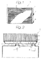
- the number 10 designates a heat exchanger for vehicles comprising two manifold tanks 11, 12, between which there extend a plurality of pipes 13 forming a heat-exchange block.
- the manifold tank 11 comprises a bottom plate 14, through which there extend the ends of the pipes 13, which are set in fluid communication with the internal space of the tank 11.
- the tank 11 is provided with two openings 15, 16 associated to respective connectors 17, 18 for connection to pipes (not illustrated) for inlet and outlet of a flow of heat-exchange fluid.
- a separating diaphragm 19 is fixed in a fluid-tight way on the inside of the manifold tank 11 and divides the internal space of the manifold tank into two chambers 20, 21.
- a heat exchanger of the above type is produced using an oven-brazing technology.
- the separating diaphragm 19 is coated with brazing alloy and is positioned between the bottom plate 14 and the manifold tank 11.
- the brazing alloy welds the separating diaphragm 19 along its perimeter to the bottom plate 14 and to the manifold tank 11.
- the ends of the pipes 13 are welded to the bottom plate 14, and the manifold tank 11 is welded to the bottom plate 14.
- Figures 1 and 2 illustrate a heat exchanger provided with a separating diaphragm 19, which extends in a direction transverse to the longitudinal axis of the manifold tank 11.
- the method according to the present invention can be used also on heat-exchangers in which the separating diaphragm extends in a direction longitudinal with respect to the manifold tank 11.
- the method for testing internal tightness according to the present invention can be applied to any heat exchanger provided with at least one manifold tank 11 in which there is provided at least one separating diaphragm that divides the internal space of the manifold tank into at least two chambers.
- the finished heat exchanger 10, i.e., at the end of the brazing operation, is subjected to a testing method according to the present invention.
- Said testing method uses a device including a supporting surface 22 provided with openings 23, 24, which are equipped with respective connectors designed for engaging the connectors 17, 18 of the heat exchanger 10.
- the testing device comprises a source of light radiation 25 and a detecting element 26 sensitive to the light radiation emitted by the source 25.
- the source of light radiation 25 and the detecting element 26 are in a fixed position with respect to the surface 22 and project from the surface in such a way that when the radiator 10 is positioned with the connectors 17, 18 engaged with the openings 23, 24 of the surface 22, the source 25 and the receiving element 26 extend inside the respective chambers 21, 20.
- the light-radiation source 25 is connected to an electrical-supply device 27.
- the detecting element 26 is connected to a device for receiving a signal 28, which receives an electrical signal emitted by the detecting element 26 and issues a signal indicating the level of internal tightness of the heat exchanger 10.
- the source of light radiation 25 can emit infrared, ultraviolet or else visible-light radiation.
- the present applicant has found experimentally that the light intensity received by the detecting element 26 is proportional to the internal losses of liquid through the diaphragm 19. In fact, the only direct communication between the chambers 20, 21, through which the light radiation emitted by the source 25 can propagate, is represented by the imperfections of tightness along the perimeter of the diaphragm 19.
- a measurement of the level of light intensity received by the detecting element 26 provides a precise indication of the level of internal leakage, i.e., of the quantity of fluid which, in use, would pass directly from one of the two chambers 20, 21 to the other, without traversing the pipes 13.
- a further advantage of the method according to the present invention lies in the fact that the above measurement can be made simultaneously with the measurement of external tightness, which consists in introducing a flow of gas inside the heat exchanger. In fact, the light source 25 and the receiving element 26 are not affected by the presence of a gas under pressure. Consequently, testing of internal tightness can be performed while the heat exchanger 10 is pressurized for carrying out the testing of the tightness towards the outside, without therefore increasing the time for the cycle of production of the heat exchanger.
Landscapes
- Physics & Mathematics (AREA)
- General Physics & Mathematics (AREA)
- Examining Or Testing Airtightness (AREA)
Abstract
Description
- The present invention relates to a method for testing the internal tightness of a heat exchanger.
- The present invention has been developed in particular for testing the internal tightness of heat-exchangers for motor vehicles, comprising a plurality of pipes designed to be traversed by a flow of liquid and connected to at least one manifold tank provided with at least one diaphragm, which divides the internal space of the manifold tank into at least two chambers provided with respective openings for inlet and outlet of the flow of liquid.
- In heat-exchangers of the above kind, there are two types of tightness: tightness towards the outside of the heat exchanger, and internal tightness. In a heat exchanger in which the inlet and outlet of the fluid flow are on said manifold tank, an internal loss brings about the passage of part of the flow of liquid directly from the inlet opening towards the outlet opening. Said loss reduces the quantity of flow that effectively traverses the pipes of the heat exchanger and leads to a reduction in heat-exchange efficiency.
- Checking of the tightness towards the outside can be performed in a relatively simple and fast way, for example by pressurizing the heat exchanger with a flow of gas and measuring the reduction in pressure of the gas. A measurement of this type can be automated in a relatively simple way, so that in lines for the production of heat-exchangers for motor vehicles there is usually provided a station for testing tightness towards the outside.
- Testing of internal tightness is, instead, decidedly more laborious. The system of internal testing usually adopted consists in setting the heat exchanger in a vertical position, with the two openings oriented downwards. One of the two openings is connected to a supply of liquid with a head having a height smaller than the height of the heat exchanger. After a sufficient length of time for obtaining filling of the pipes, the internal leakage is noted by measuring the quantity of liquid that comes out of the other opening in a pre-determined time interval. This type of testing involves very long time intervals. Consequently, it is usually carried out off the assembly line and on a statistical basis. The long time intervals necessary for testing the internal tightness with a measuring system employing a liquid head renders a check on the assembly line of each heat exchanger produced practically impossible.
- The object of the present invention is to provide a simple, rapid and reliable method for checking the internal tightness of a heat exchanger.
- According to the present invention, this object is achieved by a method having the characteristics forming the subject of the ensuing claims.
- The present invention will now be described in detail with reference to the attached drawings, which are provided purely by way of non-limiting example and in which:
- Figure 1 is a side view of a heat exchanger for motor vehicles; and
- Figure 2 is a schematic view illustrating the method for testing internal tightness of the heat exchanger as illustrated in Figure 1.
- With reference to Figure 1, the
number 10 designates a heat exchanger for vehicles comprising twomanifold tanks pipes 13 forming a heat-exchange block. - With reference to Figure 2, the
manifold tank 11 comprises a bottom plate 14, through which there extend the ends of thepipes 13, which are set in fluid communication with the internal space of thetank 11. Thetank 11 is provided with twoopenings respective connectors separating diaphragm 19 is fixed in a fluid-tight way on the inside of themanifold tank 11 and divides the internal space of the manifold tank into twochambers 20, 21. - Typically, a heat exchanger of the above type is produced using an oven-brazing technology. The separating
diaphragm 19 is coated with brazing alloy and is positioned between the bottom plate 14 and themanifold tank 11. During oven brazing, the brazing alloy welds theseparating diaphragm 19 along its perimeter to the bottom plate 14 and to themanifold tank 11. During the said brazing step, the ends of thepipes 13 are welded to the bottom plate 14, and themanifold tank 11 is welded to the bottom plate 14. - Figures 1 and 2 illustrate a heat exchanger provided with a
separating diaphragm 19, which extends in a direction transverse to the longitudinal axis of themanifold tank 11. The method according to the present invention can be used also on heat-exchangers in which the separating diaphragm extends in a direction longitudinal with respect to themanifold tank 11. The method for testing internal tightness according to the present invention can be applied to any heat exchanger provided with at least onemanifold tank 11 in which there is provided at least one separating diaphragm that divides the internal space of the manifold tank into at least two chambers. - The finished
heat exchanger 10, i.e., at the end of the brazing operation, is subjected to a testing method according to the present invention. Said testing method uses a device including a supportingsurface 22 provided withopenings connectors heat exchanger 10. The testing device comprises a source of light radiation 25 and a detectingelement 26 sensitive to the light radiation emitted by the source 25. The source of light radiation 25 and the detectingelement 26 are in a fixed position with respect to thesurface 22 and project from the surface in such a way that when theradiator 10 is positioned with theconnectors openings surface 22, the source 25 and thereceiving element 26 extend inside therespective chambers 21, 20. - The light-radiation source 25 is connected to an electrical-
supply device 27. The detectingelement 26 is connected to a device for receiving asignal 28, which receives an electrical signal emitted by the detectingelement 26 and issues a signal indicating the level of internal tightness of theheat exchanger 10. The source of light radiation 25 can emit infrared, ultraviolet or else visible-light radiation. The present applicant has found experimentally that the light intensity received by the detectingelement 26 is proportional to the internal losses of liquid through thediaphragm 19. In fact, the only direct communication between thechambers 20, 21, through which the light radiation emitted by the source 25 can propagate, is represented by the imperfections of tightness along the perimeter of thediaphragm 19. Consequently, a measurement of the level of light intensity received by the detectingelement 26 provides a precise indication of the level of internal leakage, i.e., of the quantity of fluid which, in use, would pass directly from one of the twochambers 20, 21 to the other, without traversing thepipes 13. - Testing of internal tightness by means of emission and reception of light radiation enables nondestructive testing of the internal tightness of a heat exchanger, without having to introduce a fluid inside the heat exchanger. Consequently, this type of testing is extremely rapid and can be carried out systematically on each heat exchanger manufactured. In addition, this testing method can easily be automated and provides a precise measurement of the level of internal tightness. A further advantage of the method according to the present invention lies in the fact that the above measurement can be made simultaneously with the measurement of external tightness, which consists in introducing a flow of gas inside the heat exchanger. In fact, the light source 25 and the
receiving element 26 are not affected by the presence of a gas under pressure. Consequently, testing of internal tightness can be performed while theheat exchanger 10 is pressurized for carrying out the testing of the tightness towards the outside, without therefore increasing the time for the cycle of production of the heat exchanger.
Claims (4)
- A method for testing the internal tightness of a heat exchanger comprising at least one manifold tank (11) provided with at least one separating diaphragm (19), which divides the internal space of the manifold tank (11) into at least two chambers (20, 21), the method being characterized by emitting light radiation in one of said chambers (20, 21) and by determining the internal tightness of the heat exchanger according to the intensity of the light radiation received in the other chamber (20, 21).
- The method according to Claim 1, characterized in that it comprises the steps of inserting, in the aforesaid chambers (20, 21), a source of light radiation (25) and a detecting element (26) sensitive to the light radiation emitted by said source (25).
- The method according to Claim 2, characterized in that said detecting element (26) is connected to a circuit (28) designed for receiving an electrical signal coming from said detecting element (26) and for issuing a signal indicating the degree of internal tightness of the heat exchanger according to the intensity of the electrical signal received by said detecting element (26).
- The method according to Claim 1, characterized in that testing of the internal tightness by means of emission and reception of light radiation is carried out simultaneously with testing of external tightness carried out by pressurizing of the heat exchanger.
Priority Applications (4)
| Application Number | Priority Date | Filing Date | Title |
|---|---|---|---|
| EP02425711A EP1422506B1 (en) | 2002-11-19 | 2002-11-19 | A method for testing the internal tightness of a heat exchanger |
| DE60208655T DE60208655T2 (en) | 2002-11-19 | 2002-11-19 | Method for testing the internal tightness of heat exchangers |
| ES02425711T ES2252420T3 (en) | 2002-11-19 | 2002-11-19 | METHOD FOR TESTING THE INTERNAL SEALING OF A HEAT EXCHANGER. |
| AT02425711T ATE315777T1 (en) | 2002-11-19 | 2002-11-19 | METHOD FOR TESTING THE INTERNAL TIGHTNESS OF HEAT EXCHANGERS |
Applications Claiming Priority (1)
| Application Number | Priority Date | Filing Date | Title |
|---|---|---|---|
| EP02425711A EP1422506B1 (en) | 2002-11-19 | 2002-11-19 | A method for testing the internal tightness of a heat exchanger |
Publications (2)
| Publication Number | Publication Date |
|---|---|
| EP1422506A1 true EP1422506A1 (en) | 2004-05-26 |
| EP1422506B1 EP1422506B1 (en) | 2006-01-11 |
Family
ID=32187313
Family Applications (1)
| Application Number | Title | Priority Date | Filing Date |
|---|---|---|---|
| EP02425711A Expired - Lifetime EP1422506B1 (en) | 2002-11-19 | 2002-11-19 | A method for testing the internal tightness of a heat exchanger |
Country Status (4)
| Country | Link |
|---|---|
| EP (1) | EP1422506B1 (en) |
| AT (1) | ATE315777T1 (en) |
| DE (1) | DE60208655T2 (en) |
| ES (1) | ES2252420T3 (en) |
Cited By (1)
| Publication number | Priority date | Publication date | Assignee | Title |
|---|---|---|---|---|
| WO2006063853A1 (en) | 2004-12-18 | 2006-06-22 | Sms Demag Ag | Metallurgical vessel comprising a light sensor for detection of water leaks |
Citations (5)
| Publication number | Priority date | Publication date | Assignee | Title |
|---|---|---|---|---|
| US4947931A (en) * | 1989-12-28 | 1990-08-14 | Vitacco Richard L | Plastic vehicular radiator-condenser with metal cooling inserts |
| US5548400A (en) * | 1994-02-16 | 1996-08-20 | Sochata | Method and apparatus for inspecting honeycomb structures using optical fibres |
| DE19613560A1 (en) * | 1996-04-04 | 1997-10-09 | Krupp Ag Hoesch Krupp | Leak testing method for open hollow body made of light impermeable material e.g. tin |
| JPH1038745A (en) * | 1996-07-23 | 1998-02-13 | Umeoka Radiator Kogyosho:Kk | Leak tester for radiator and control board therefor |
| US6452670B1 (en) * | 1998-10-29 | 2002-09-17 | Societe Nationale d'Etude et de Construction de Moteurs d'Aviation “SNECMA” | Process and instrument for checking the bonding of the cellular core of a honeycomb to a skin |
-
2002
- 2002-11-19 AT AT02425711T patent/ATE315777T1/en not_active IP Right Cessation
- 2002-11-19 ES ES02425711T patent/ES2252420T3/en not_active Expired - Lifetime
- 2002-11-19 EP EP02425711A patent/EP1422506B1/en not_active Expired - Lifetime
- 2002-11-19 DE DE60208655T patent/DE60208655T2/en not_active Expired - Lifetime
Patent Citations (5)
| Publication number | Priority date | Publication date | Assignee | Title |
|---|---|---|---|---|
| US4947931A (en) * | 1989-12-28 | 1990-08-14 | Vitacco Richard L | Plastic vehicular radiator-condenser with metal cooling inserts |
| US5548400A (en) * | 1994-02-16 | 1996-08-20 | Sochata | Method and apparatus for inspecting honeycomb structures using optical fibres |
| DE19613560A1 (en) * | 1996-04-04 | 1997-10-09 | Krupp Ag Hoesch Krupp | Leak testing method for open hollow body made of light impermeable material e.g. tin |
| JPH1038745A (en) * | 1996-07-23 | 1998-02-13 | Umeoka Radiator Kogyosho:Kk | Leak tester for radiator and control board therefor |
| US6452670B1 (en) * | 1998-10-29 | 2002-09-17 | Societe Nationale d'Etude et de Construction de Moteurs d'Aviation “SNECMA” | Process and instrument for checking the bonding of the cellular core of a honeycomb to a skin |
Non-Patent Citations (1)
| Title |
|---|
| PATENT ABSTRACTS OF JAPAN vol. 1998, no. 06 30 April 1998 (1998-04-30) * |
Cited By (1)
| Publication number | Priority date | Publication date | Assignee | Title |
|---|---|---|---|---|
| WO2006063853A1 (en) | 2004-12-18 | 2006-06-22 | Sms Demag Ag | Metallurgical vessel comprising a light sensor for detection of water leaks |
Also Published As
| Publication number | Publication date |
|---|---|
| ES2252420T3 (en) | 2006-05-16 |
| ATE315777T1 (en) | 2006-02-15 |
| EP1422506B1 (en) | 2006-01-11 |
| DE60208655D1 (en) | 2006-04-06 |
| DE60208655T2 (en) | 2006-07-27 |
Similar Documents
| Publication | Publication Date | Title |
|---|---|---|
| JPH0255928A (en) | Leak inspector | |
| US4905501A (en) | Jig for leak check | |
| EP1422506B1 (en) | A method for testing the internal tightness of a heat exchanger | |
| KR101495753B1 (en) | Apparatus for detecting leak of heat exchanger | |
| CN103424412A (en) | Composite gas cylinder detecting system based on infrared thermal imaging | |
| CN213336621U (en) | Gauge pressure sensor calibration tool | |
| CN221898707U (en) | A dual-station testing platform for valve sealing performance | |
| CN211528175U (en) | Anticorrosive testing arrangement of anticorrosive pipe | |
| JP4364218B2 (en) | Leak inspection method and leak inspection apparatus | |
| CN216669156U (en) | Electrode holder leak hunting device | |
| US6786079B2 (en) | Apparatus and method for testing a recuperator core for leakage | |
| CN215573258U (en) | Pulsation detection device of ultrasonic gas meter | |
| CN210863072U (en) | Pipe nozzle leakage tester | |
| CN107631842B (en) | A detection device for detecting leakage of a heat collecting pipeline and its use method | |
| CN222866147U (en) | Pipeline gas tightness detection device | |
| JPH075391Y2 (en) | Tube bundle tester for heat exchanger | |
| CN221992955U (en) | Solar copper pipe sealing detection device | |
| CN222671344U (en) | Helium detection tool for detecting leakage in cooling pipe | |
| KR101420313B1 (en) | Testing method of pipe connecting part | |
| CN217006250U (en) | Air bag device for checking tube bundle leakage points | |
| CN217155453U (en) | High-precision capillary tube blockage detecting machine | |
| CN218765790U (en) | Manometer precision measurement appearance | |
| RU2257304C2 (en) | Method of manufacture of tank barrel with heating jacket | |
| CN213301599U (en) | Mechanism for conducting and detecting aperture size of fuel distribution pipe | |
| CN219694440U (en) | Leak detection tool for stop valve |
Legal Events
| Date | Code | Title | Description |
|---|---|---|---|
| PUAI | Public reference made under article 153(3) epc to a published international application that has entered the european phase |
Free format text: ORIGINAL CODE: 0009012 |
|
| 17P | Request for examination filed |
Effective date: 20031003 |
|
| AK | Designated contracting states |
Kind code of ref document: A1 Designated state(s): AT BE BG CH CY CZ DE DK EE ES FI FR GB GR IE IT LI LU MC NL PT SE SK TR |
|
| AX | Request for extension of the european patent |
Extension state: AL LT LV MK RO SI |
|
| AKX | Designation fees paid |
Designated state(s): AT BE BG CH CY CZ DE DK EE ES FI FR GB GR IE IT LI LU MC NL PT SE SK TR |
|
| 17Q | First examination report despatched |
Effective date: 20050217 |
|
| GRAP | Despatch of communication of intention to grant a patent |
Free format text: ORIGINAL CODE: EPIDOSNIGR1 |
|
| GRAS | Grant fee paid |
Free format text: ORIGINAL CODE: EPIDOSNIGR3 |
|
| GRAA | (expected) grant |
Free format text: ORIGINAL CODE: 0009210 |
|
| AK | Designated contracting states |
Kind code of ref document: B1 Designated state(s): AT BE BG CH CY CZ DE DK EE ES FI FR GB GR IE IT LI LU MC NL PT SE SK TR |
|
| PG25 | Lapsed in a contracting state [announced via postgrant information from national office to epo] |
Ref country code: IT Free format text: LAPSE BECAUSE OF FAILURE TO SUBMIT A TRANSLATION OF THE DESCRIPTION OR TO PAY THE FEE WITHIN THE PRESCRIBED TIME-LIMIT;WARNING: LAPSES OF ITALIAN PATENTS WITH EFFECTIVE DATE BEFORE 2007 MAY HAVE OCCURRED AT ANY TIME BEFORE 2007. THE CORRECT EFFECTIVE DATE MAY BE DIFFERENT FROM THE ONE RECORDED. Effective date: 20060111 Ref country code: LI Free format text: LAPSE BECAUSE OF FAILURE TO SUBMIT A TRANSLATION OF THE DESCRIPTION OR TO PAY THE FEE WITHIN THE PRESCRIBED TIME-LIMIT Effective date: 20060111 Ref country code: FI Free format text: LAPSE BECAUSE OF FAILURE TO SUBMIT A TRANSLATION OF THE DESCRIPTION OR TO PAY THE FEE WITHIN THE PRESCRIBED TIME-LIMIT Effective date: 20060111 Ref country code: AT Free format text: LAPSE BECAUSE OF FAILURE TO SUBMIT A TRANSLATION OF THE DESCRIPTION OR TO PAY THE FEE WITHIN THE PRESCRIBED TIME-LIMIT Effective date: 20060111 Ref country code: SK Free format text: LAPSE BECAUSE OF FAILURE TO SUBMIT A TRANSLATION OF THE DESCRIPTION OR TO PAY THE FEE WITHIN THE PRESCRIBED TIME-LIMIT Effective date: 20060111 Ref country code: CH Free format text: LAPSE BECAUSE OF FAILURE TO SUBMIT A TRANSLATION OF THE DESCRIPTION OR TO PAY THE FEE WITHIN THE PRESCRIBED TIME-LIMIT Effective date: 20060111 Ref country code: NL Free format text: LAPSE BECAUSE OF FAILURE TO SUBMIT A TRANSLATION OF THE DESCRIPTION OR TO PAY THE FEE WITHIN THE PRESCRIBED TIME-LIMIT Effective date: 20060111 Ref country code: BE Free format text: LAPSE BECAUSE OF FAILURE TO SUBMIT A TRANSLATION OF THE DESCRIPTION OR TO PAY THE FEE WITHIN THE PRESCRIBED TIME-LIMIT Effective date: 20060111 |
|
| REG | Reference to a national code |
Ref country code: CH Ref legal event code: EP |
|
| REG | Reference to a national code |
Ref country code: IE Ref legal event code: FG4D |
|
| REG | Reference to a national code |
Ref country code: SE Ref legal event code: TRGR |
|
| REF | Corresponds to: |
Ref document number: 60208655 Country of ref document: DE Date of ref document: 20060406 Kind code of ref document: P |
|
| PG25 | Lapsed in a contracting state [announced via postgrant information from national office to epo] |
Ref country code: BG Free format text: LAPSE BECAUSE OF FAILURE TO SUBMIT A TRANSLATION OF THE DESCRIPTION OR TO PAY THE FEE WITHIN THE PRESCRIBED TIME-LIMIT Effective date: 20060411 Ref country code: DK Free format text: LAPSE BECAUSE OF FAILURE TO SUBMIT A TRANSLATION OF THE DESCRIPTION OR TO PAY THE FEE WITHIN THE PRESCRIBED TIME-LIMIT Effective date: 20060411 |
|
| REG | Reference to a national code |
Ref country code: ES Ref legal event code: FG2A Ref document number: 2252420 Country of ref document: ES Kind code of ref document: T3 |
|
| PG25 | Lapsed in a contracting state [announced via postgrant information from national office to epo] |
Ref country code: PT Free format text: LAPSE BECAUSE OF FAILURE TO SUBMIT A TRANSLATION OF THE DESCRIPTION OR TO PAY THE FEE WITHIN THE PRESCRIBED TIME-LIMIT Effective date: 20060612 |
|
| NLV1 | Nl: lapsed or annulled due to failure to fulfill the requirements of art. 29p and 29m of the patents act | ||
| REG | Reference to a national code |
Ref country code: CH Ref legal event code: PL |
|
| ET | Fr: translation filed | ||
| PLBE | No opposition filed within time limit |
Free format text: ORIGINAL CODE: 0009261 |
|
| STAA | Information on the status of an ep patent application or granted ep patent |
Free format text: STATUS: NO OPPOSITION FILED WITHIN TIME LIMIT |
|
| PG25 | Lapsed in a contracting state [announced via postgrant information from national office to epo] |
Ref country code: IE Free format text: LAPSE BECAUSE OF NON-PAYMENT OF DUE FEES Effective date: 20061120 |
|
| PG25 | Lapsed in a contracting state [announced via postgrant information from national office to epo] |
Ref country code: MC Free format text: LAPSE BECAUSE OF NON-PAYMENT OF DUE FEES Effective date: 20061130 |
|
| 26N | No opposition filed |
Effective date: 20061012 |
|
| PG25 | Lapsed in a contracting state [announced via postgrant information from national office to epo] |
Ref country code: GR Free format text: LAPSE BECAUSE OF FAILURE TO SUBMIT A TRANSLATION OF THE DESCRIPTION OR TO PAY THE FEE WITHIN THE PRESCRIBED TIME-LIMIT Effective date: 20060412 Ref country code: CZ Free format text: LAPSE BECAUSE OF FAILURE TO SUBMIT A TRANSLATION OF THE DESCRIPTION OR TO PAY THE FEE WITHIN THE PRESCRIBED TIME-LIMIT Effective date: 20060111 |
|
| PG25 | Lapsed in a contracting state [announced via postgrant information from national office to epo] |
Ref country code: EE Free format text: LAPSE BECAUSE OF FAILURE TO SUBMIT A TRANSLATION OF THE DESCRIPTION OR TO PAY THE FEE WITHIN THE PRESCRIBED TIME-LIMIT Effective date: 20060111 |
|
| PG25 | Lapsed in a contracting state [announced via postgrant information from national office to epo] |
Ref country code: LU Free format text: LAPSE BECAUSE OF NON-PAYMENT OF DUE FEES Effective date: 20061119 Ref country code: TR Free format text: LAPSE BECAUSE OF FAILURE TO SUBMIT A TRANSLATION OF THE DESCRIPTION OR TO PAY THE FEE WITHIN THE PRESCRIBED TIME-LIMIT Effective date: 20060111 |
|
| PG25 | Lapsed in a contracting state [announced via postgrant information from national office to epo] |
Ref country code: CY Free format text: LAPSE BECAUSE OF FAILURE TO SUBMIT A TRANSLATION OF THE DESCRIPTION OR TO PAY THE FEE WITHIN THE PRESCRIBED TIME-LIMIT Effective date: 20060111 |
|
| PGFP | Annual fee paid to national office [announced via postgrant information from national office to epo] |
Ref country code: SE Payment date: 20081107 Year of fee payment: 7 |
|
| PGFP | Annual fee paid to national office [announced via postgrant information from national office to epo] |
Ref country code: GB Payment date: 20081119 Year of fee payment: 7 |
|
| EUG | Se: european patent has lapsed | ||
| GBPC | Gb: european patent ceased through non-payment of renewal fee |
Effective date: 20091119 |
|
| PG25 | Lapsed in a contracting state [announced via postgrant information from national office to epo] |
Ref country code: GB Free format text: LAPSE BECAUSE OF NON-PAYMENT OF DUE FEES Effective date: 20091119 |
|
| PGFP | Annual fee paid to national office [announced via postgrant information from national office to epo] |
Ref country code: IT Payment date: 20101116 Year of fee payment: 9 |
|
| PG25 | Lapsed in a contracting state [announced via postgrant information from national office to epo] |
Ref country code: SE Free format text: LAPSE BECAUSE OF NON-PAYMENT OF DUE FEES Effective date: 20091120 |
|
| PGFP | Annual fee paid to national office [announced via postgrant information from national office to epo] |
Ref country code: ES Payment date: 20111124 Year of fee payment: 10 Ref country code: FR Payment date: 20120106 Year of fee payment: 10 |
|
| PGFP | Annual fee paid to national office [announced via postgrant information from national office to epo] |
Ref country code: DE Payment date: 20120131 Year of fee payment: 10 |
|
| REG | Reference to a national code |
Ref country code: DE Ref legal event code: R231 Ref document number: 60208655 Country of ref document: DE |
|
| REG | Reference to a national code |
Ref country code: FR Ref legal event code: ST Effective date: 20130731 |
|
| PG25 | Lapsed in a contracting state [announced via postgrant information from national office to epo] |
Ref country code: IT Free format text: LAPSE BECAUSE OF NON-PAYMENT OF DUE FEES Effective date: 20121119 |
|
| PG25 | Lapsed in a contracting state [announced via postgrant information from national office to epo] |
Ref country code: FR Free format text: LAPSE BECAUSE OF NON-PAYMENT OF DUE FEES Effective date: 20121130 |
|
| REG | Reference to a national code |
Ref country code: ES Ref legal event code: FD2A Effective date: 20140305 |
|
| PG25 | Lapsed in a contracting state [announced via postgrant information from national office to epo] |
Ref country code: ES Free format text: LAPSE BECAUSE OF NON-PAYMENT OF DUE FEES Effective date: 20121120 |
|
| PG25 | Lapsed in a contracting state [announced via postgrant information from national office to epo] |
Ref country code: DE Free format text: LAPSE BECAUSE OF THE APPLICANT RENOUNCES Effective date: 20121115 |