EP1422175B1 - Splicing device for splicing two web materials together, unwinder comprising said splicing device and relative method - Google Patents
Splicing device for splicing two web materials together, unwinder comprising said splicing device and relative method Download PDFInfo
- Publication number
- EP1422175B1 EP1422175B1 EP03425616A EP03425616A EP1422175B1 EP 1422175 B1 EP1422175 B1 EP 1422175B1 EP 03425616 A EP03425616 A EP 03425616A EP 03425616 A EP03425616 A EP 03425616A EP 1422175 B1 EP1422175 B1 EP 1422175B1
- Authority
- EP
- European Patent Office
- Prior art keywords
- roller
- web material
- counter
- splicing device
- clamping bar
- Prior art date
- Legal status (The legal status is an assumption and is not a legal conclusion. Google has not performed a legal analysis and makes no representation as to the accuracy of the status listed.)
- Expired - Lifetime
Links
Images




Classifications
-
- B—PERFORMING OPERATIONS; TRANSPORTING
- B65—CONVEYING; PACKING; STORING; HANDLING THIN OR FILAMENTARY MATERIAL
- B65H—HANDLING THIN OR FILAMENTARY MATERIAL, e.g. SHEETS, WEBS, CABLES
- B65H19/00—Changing the web roll
- B65H19/10—Changing the web roll in unwinding mechanisms or in connection with unwinding operations
- B65H19/18—Attaching, e.g. pasting, the replacement web to the expiring web
- B65H19/1805—Flying splicing, i.e. the expiring web moving during splicing contact
- B65H19/1826—Flying splicing, i.e. the expiring web moving during splicing contact taking place at a distance from the replacement roll
- B65H19/1836—Flying splicing, i.e. the expiring web moving during splicing contact taking place at a distance from the replacement roll the replacement web being accelerated or running prior to splicing contact
-
- B—PERFORMING OPERATIONS; TRANSPORTING
- B65—CONVEYING; PACKING; STORING; HANDLING THIN OR FILAMENTARY MATERIAL
- B65H—HANDLING THIN OR FILAMENTARY MATERIAL, e.g. SHEETS, WEBS, CABLES
- B65H2301/00—Handling processes for sheets or webs
- B65H2301/40—Type of handling process
- B65H2301/46—Splicing
- B65H2301/461—Processing webs in splicing process
- B65H2301/4615—Processing webs in splicing process after splicing
- B65H2301/4617—Processing webs in splicing process after splicing cutting webs in splicing process
- B65H2301/46172—Processing webs in splicing process after splicing cutting webs in splicing process cutting expiring web only
-
- B—PERFORMING OPERATIONS; TRANSPORTING
- B65—CONVEYING; PACKING; STORING; HANDLING THIN OR FILAMENTARY MATERIAL
- B65H—HANDLING THIN OR FILAMENTARY MATERIAL, e.g. SHEETS, WEBS, CABLES
- B65H2301/00—Handling processes for sheets or webs
- B65H2301/40—Type of handling process
- B65H2301/46—Splicing
- B65H2301/462—Form of splice
- B65H2301/4621—Overlapping article or web portions
-
- B—PERFORMING OPERATIONS; TRANSPORTING
- B65—CONVEYING; PACKING; STORING; HANDLING THIN OR FILAMENTARY MATERIAL
- B65H—HANDLING THIN OR FILAMENTARY MATERIAL, e.g. SHEETS, WEBS, CABLES
- B65H2301/00—Handling processes for sheets or webs
- B65H2301/40—Type of handling process
- B65H2301/46—Splicing
- B65H2301/463—Splicing splicing means, i.e. means by which a web end is bound to another web end
- B65H2301/4631—Adhesive tape
- B65H2301/46312—Adhesive tape double-sided
-
- B—PERFORMING OPERATIONS; TRANSPORTING
- B65—CONVEYING; PACKING; STORING; HANDLING THIN OR FILAMENTARY MATERIAL
- B65H—HANDLING THIN OR FILAMENTARY MATERIAL, e.g. SHEETS, WEBS, CABLES
- B65H2301/00—Handling processes for sheets or webs
- B65H2301/40—Type of handling process
- B65H2301/46—Splicing
- B65H2301/464—Splicing effecting splice
- B65H2301/4641—Splicing effecting splice by pivoting element
-
- B—PERFORMING OPERATIONS; TRANSPORTING
- B65—CONVEYING; PACKING; STORING; HANDLING THIN OR FILAMENTARY MATERIAL
- B65H—HANDLING THIN OR FILAMENTARY MATERIAL, e.g. SHEETS, WEBS, CABLES
- B65H2301/00—Handling processes for sheets or webs
- B65H2301/40—Type of handling process
- B65H2301/46—Splicing
- B65H2301/464—Splicing effecting splice
- B65H2301/46412—Splicing effecting splice by element moving in a direction perpendicular to the running direction of the web
-
- B—PERFORMING OPERATIONS; TRANSPORTING
- B65—CONVEYING; PACKING; STORING; HANDLING THIN OR FILAMENTARY MATERIAL
- B65H—HANDLING THIN OR FILAMENTARY MATERIAL, e.g. SHEETS, WEBS, CABLES
- B65H2408/00—Specific machines
- B65H2408/20—Specific machines for handling web(s)
- B65H2408/22—Splicing machines
- B65H2408/221—Splicing machines features of splicing unit
- B65H2408/2211—Splicing machines features of splicing unit splicing unit located above several web rolls arranged parallel to each other
-
- B—PERFORMING OPERATIONS; TRANSPORTING
- B65—CONVEYING; PACKING; STORING; HANDLING THIN OR FILAMENTARY MATERIAL
- B65H—HANDLING THIN OR FILAMENTARY MATERIAL, e.g. SHEETS, WEBS, CABLES
- B65H2701/00—Handled material; Storage means
- B65H2701/10—Handled articles or webs
- B65H2701/17—Nature of material
- B65H2701/176—Cardboard
- B65H2701/1762—Corrugated
Definitions
- the present invention relates to a device to splice two webs together, for example two sheets of cardboard, to allow continuous feed of a web material wound in reels towards a processing line, for example a machine to produce corrugated cardboard.
- the invention also relates to an unwinding device in which reels of web material are unwound in succession, equipped with a splicing device to splice a first web material coming from a reel being unwound to the head or leading edge of a second web material coming from a standing by reel.
- a web material coming from a reel being unwound is fed towards a production line.
- the web material is fed to a so-called “single-facer” or to a so-called “double-facer” to be combined with other sheets of web material, if necessary after corrugation of the material.
- the web material coming from a first reel of web material must be spliced to the web material coming from a second reel, for example when the first reel is coming to an end.
- This operation must preferably take place without reducing the feed speed of the material to the production line and in any case without stopping feed.
- Regular feed is particularly important in corrugated cardboard production lines, where the machines downstream of the unwinder work at high temperatures and in which the speed and regularity of feed are critical parameters to obtain a high quality finished product.
- US-A-3,858,819 describes a device provided with two bars moving crosswise in relation to the direction of feed of the web material and to which the leading free edge of the web material of a supply reel standing by is alternately fixed.
- a double counter-blade cooperating alternately with two cutting blades, is provided under the two bars.
- a first actuator for each assembly formed of bar and cutting blade causes a reciprocal drawing in movement of the bars to press the two web materials to be spliced against each other.
- Two actuators are also provided, one for each cutting blade, which are operated alternately to cut the web material which is running out.
- GB-A-1,569,886 describes a splicing device in which the two web materials are spliced by reciprocal pressure between two rollers, with which a cutting blade is associated. This device is also complex due to the need to provide several actuators to control the various members of the splicing device. The speeds that can be reached are limited.
- Fig. 1 schematically represents a head of a different prior art splicing device produced by BHS (Germany) see also US 5,171,396 .
- This device comprises two heads similar to each other.
- the head shown in Fig.1 comprises a roller 1 associated with a clamping bar 3.
- the leading edge L of the web material N2 coming from a waiting reel (not shown) is held between the roller 1 and the bar 3 and a double-sided adhesive strip BA is applied to it.
- the web material N1 coming from the reel (not shown) which is currently supplying the material to the production line, passes between the roller 1 and a second counter-pressure roller 5.
- a cutting blade 7 is positioned adjacent to the roller 5.
- a brake 9 is provided to clamp the web material N1 at the moment in which the splice is to be made between the first and second web material.
- the members 3, 5, 7 and 9 are provided with respective actuators (shown schematically in Fig.1 ) which control the following operating sequence: the web material N1 is braked and clamped by lowering the brake 9 which presses against the upper surface of the bar 3; the roller 5 is lowered and pressed against the roller 1; the cutting blade 7 acts to cut the web N1 by being lowered towards the roller 1; the cutting blade 7, the clamping bar 3 and the brake 9 are withdrawn, moving away from the roller 1; the roller 1 and the roller 5 start to rotate in opposite directions to feed the web material N2, the leading edge L of which is spliced to the tail of the web material N1 produced by the cut made by the blade 7. Splicing is obtained by adhesion by means of a strip of double-sided adhesive tape applied previously to the edge L, thanks to the pressure exerted by the rollers 1, 5 on the web materials N1, N2 which are fed through the nip between the rollers.
- the device in Fig.1 is relatively fast, but extremely complex due to the numerous moving members provided with autonomous controls.
- the various movements must be coordinated and synchronized with one another.
- the short time available for splicing the web materials makes synchronization critical. This reduces the reliability of the device and in any case places a limit on the maximum admissible operating speed.
- the object of the present invention is to produce a device to splice together two web materials, which overcomes the drawbacks of prior art devices and in particular is of simple construction, fast and reliable.
- a splicing device comprising two heads, each of which has: a roller associated with a clamping bar to hold between said roller and said clamping bar an leading edge of the second web material; a counter-pressure member cooperating with said roller to press said first and second web materials against each other; a cutting member; if necessary a braking means to brake the first web material.
- the counter-pressure member, the cutting member and the braking means if provided are carried by a moving unit controlled by an actuator which, through a movement imparted by it to said unit, causes clamping of the first web material through said braking means, nipping of the first and second web material between said roller and said counter-pressure member, cutting of the first web material by said cutting member and release of the second web material through a movement of said roller in respect of said clamping bar, the roller being pushed by said counter-pressure member.
- each head of the splicing device may be provided for example with a translatory movement. Nonetheless, according to a particularly advantageous embodiment of the invention it is provided with an oscillatory movement around a first axis of oscillation, controlled by said actuator.
- the counter-pressure member of each of said heads is supported by the moving unit oscillatingly around a second axis of oscillation, substantially parallel to said first axis of oscillation.
- it has a substantially cylindrical surface cooperating with the roller.
- the counter-pressure member does not require to be produced in the form of a roller, but may have an active surface constituted by a portion of a cylindrical surface. This greatly reduces its dimensions and allows the various members carried by the moving unit to be positioned close to one another. In particular, the cutting member is thus in an optimum position to cut the web material.
- Another object of the invention is an unwinder provided with a splicing device of the aforesaid type.
- Figs. 2 to 5 show in different operating positions an unwinder to feed a web material to a processing line downstream, not shown.
- a splicing device according to the invention is combined with the unwinder.
- the unwinder illustrated is particularly suitable to feed sheets or webs of cardboard to produce corrugated cardboard.
- the structure of the unwinder, indicated as a whole with 1, may be different from that show in the figures, the splicing device of the invention also being suitable for application in unwinders differing in arrangement.
- the unwinder has a fixed structure with two pairs of uprights 3 (a single upright of each pair being visible in the drawing) and a pair of crosspieces 5 (of which one is visible in the drawing while the other is disposed behind it).
- the crosspieces 5 carry guides 7 for a pair of carriages or slides 9A and 9B.
- Each carriage 9A, 9B has engaging and lifting means 11A and 11B to engage and lift or lower reels of web material.
- these means have vertical arms that extend telescopically with tailstocks that engage each reel axially penetrating from opposite parts of the winding core.
- the structure of the carriages or slides 9A, 9B and the means 11A, 11B for lifting and lowering the reels is not the specific object of the present invention and therefore shall not be described in detail herein. It must be understood, as indicated above, that the structure of the unwinder may also vary from the one illustrated; for example the reels may be handled by oscillating arms, in a per se known way. Moreover, the number of positions of the reels on the unwinder may be different to three, as shown in the example. For example, there may only be two reel loading, unloading and processing stations.
- unwinders with various structures to which a splicing device according to the invention may be applied are described for example in EP-A-1127820 , US-A-3858819 , JP-A-7157156 , JP-A-1111749 , EP-A-968945 , US-A-4919353 , US-A-5004173 .
- the crosspieces 5 have at the top an assembly of rollers defining a supply or festoon of web material for the purposes described hereunder.
- This assembly of rollers comprises a first fixed roller 13 and a second fixed roller 15, and a pair of rollers 17 and 19 with moving axis, carried by a carriage 21 sliding according to the arrow f21 along a guide 23 carried by the crosspieces 25.
- Fig.2 in the phase of operation illustrated here, three reels, indicated with BA, BB and BC, are located on the unwinder.
- the reel BA is in a central position inside the unwinder, carried by means 11A associated with the slide 9A.
- the reel BA is the one that supplies the web material, indicated with N2, towards the processing line during the phase shown in Fig.2 .
- the web material N2 follows a path defined by a roller 31 (supported with its axis fixed in relation to the slide 9A) and by a roller 33A carried by the slide 9A and oscillating around the axis 32A of the roller 31, for the purposes to be explained hereunder.
- the web material N2 is then driven around a motorized drive roller 35 against which a pressure roller 37 can press, through the effect of the action of a piston cylinder actuator.
- the purpose of the roller 35 is to accelerate the web material in the transitory phases to start feed from a new reel, as shall be better explained hereunder, and the pressure roller 37 prevents slipping between the web material and the accelerator roller 35.
- the pressure roller 37 could also be omitted.
- the reel BB is engaged by means 11B associated with the slide 9B and is in the preparation phase. This means that the initial edge of the web material N1 wound around said reel is prepared by the operator and fixed to a clamping bar of a head of the splicing device to be subsequently carried to a splicing position at the tail portion of the web material N2 coming from the reel BA.
- the reel BB will start to unwind when the reel BA comes to an end or in any case when it must be replaced.
- the two reels BA and BB may be reels of different material and replace each other when a change in the production order occurs.
- BC indicates a third reel standing by which will start to be used in place of the reel BB in a subsequent phase of processing.
- the splicing device which forms the specific object of the present invention, comprises two heads each of which is comprised of two portions which may adopt different reciprocal positions.
- 41A and 43A indicate as a whole the two portions of the first head of the splicing device (indicated as a whole as head 41A, 43A), while 41B and 43B indicate the two portions of the second head (indicated as head 41B, 43B) of the splicing device.
- the two heads are more or less identical except for the different spatial arrangement and some structural characteristics of secondary importance. Therefore, only one of these (head 41A, 43A) shall be described in particular detail hereunder also as regards its operation, while the conformation of the head 41B, 43B is described briefly with reference only to Fig.8 .
- the two portions 41A and 41B of the two heads are hinged around respective axes 45A and 45B.
- the axis 45A around which the portion 41A of the first head oscillates may be fixed in relation to the crosspiece 5
- the axis 45B of oscillation of the portion 41B of the second head is provided with a translatory movement to move the portion 41B from the position in Figs.2 and 3 to the position in Figs.4 and 5 .
- the oscillatory movement of the two portions 41A, 41B around the axes 45A, 45B is controlled by a piston-cylinder actuator indicated with 47A for the portion 41A of the head 41A, 43A and with 47B for the portion 41B of the head 41B, 43B.
- the portion 41A of the first head of the splicing device has a moving unit 49A supported around the axis 45A and the oscillation of which around said axis is controlled by the aforesaid actuator 47A.
- the moving unit 49A supports oscillatingly around an axis 51A a counter-pressure member 53A with a cylindrical surface 55A, covered with a resilient material, cooperating with the roller 33A that is part of the portion 43A of the splicing head.
- the cylindrical surface 53A constitutes a portion of a straight circular cylinder, for example limited to an arc of 10-30°. This makes the counter-pressure member 53A particularly small in size and allows other members carried by the unit 49A to be placed in an optimum position for their operation, and in a limited space.
- the cutting member 67A may be placed in close proximity to the axis of oscillation 51A of the counter-pressure member 53A.
- the cut of the material may take place extremely close to the edge of the double-sided adhesive strip applied to the new web material and destined to splice together the tail edge of one web material and the leading edge of the other.
- This is advantageous as - as is known by those skilled in the art - it is advisable for excessively long free edges not to protrude from the edge of the double-sided adhesive strip.
- the double-sided adhesive strip not to be excessively wide, also in order to reduce the quantity of material used.
- the cutting member is tilted to form an acute angle with the portion of web material downstream of the cutting point, in relation to the direction of feed of the material.
- the cutting member 67A which is usually a toothed blade
- subsequent drawing of the material does not cause it to disengage from the teeth of the blade.
- these teeth hold it until it tears along the line of the cut made by the teeth of the blade. This ensures that the web material of the reel which is running out is in any case severed.
- the axis 45A supports a pair of oscillating arms 57A carrying a crosspiece 59A with which a pad 61A is integral.
- the members 57A, 59A and 61A form a braking means, indicated as a whole with 63A, which during the splicing phase of the web materials N1 and N2 is used to clamp the web material N1.
- the braking means 63A is associated with an elastic member constituted, in the example shown, by a pneumatic spring 65A secured at one end to the oscillating arms 57A and at the opposite end to the moving unit 41A.
- the moving unit 49 also carries a cutting member 67A to cut the web material N1.
- 69A indicates an adjustable stop secured rigidly to the moving unit 49A.
- the portion 43A of the head 41A, 43A of the splicing device has a moving support 71A, hinged around the axis 32A of the roller 31 mentioned above, said axis being carried by the slide 9A.
- the oscillating movement of the moving support 71A is controlled by a piston-cylinder actuator 73A hinged in 75A to the moving support 71A and in 77A to the slide 9A.
- Hinged around an axis 79A carried by the support 71A are a pair of oscillating arms 81A which support the aforesaid roller 33A, the axis of which is indicated with 34A.
- a piston-cylinder actuator 83A Associated with the pair of oscillating arms 81A and consequently with the roller 33A supported idle by said arms is a piston-cylinder actuator 83A, which has the dual function of actuator member and elastic member, as shall become apparent hereunder.
- the piston-cylinder 83A is secured in 85A to the oscillating arms 81 and in 87A to the moving support 71A.
- a section bar 89A defining a channel 91A to trim the initial edge of the web material N2 when it is prepared for subsequent splicing to the web N1. This is a manual operation and is per se known.
- the moving support 71A supports, rigidly secured to it, a clamping bar 93A cooperating with the roller 33A, the structure of which is shown in detail in Fig.7 .
- the clamping bar 93A has a series of pads made of rubber or another elastomer or similar material, indicated with 95A.
- Elastic plates 97A made of metal or another suitable material, are inserted between them. The purpose of the pads 95A and the plates 97A is to hold, by pressing against the cylindrical surface of the roller 33A, the leading edge of the web material N2 positioned for splicing with the tail edge of the web material N1.
- the section bar forming the surface 99A also defines, together with a section bar 101A, a counter-blade or cutting channel 103A cooperating with the cutting member 67A carried by the moving unit 49A of the portion 41A of the head 41A, 43A.
- the second head of the splicing device formed by the portions 41B, 43B has a substantially identical conformation.
- the two portions 41B, 43B of the second head are shown in Fig.8 , in the position they adopt when the unwinder is in the position in Fig.3 ready to splice a web N2 being supplied to a web N1 standing by.
- Identical or equivalent parts to those of the first head 41A, 43A of the splicing device are indicated with the same reference numbers followed by the letter B instead of the letter A.
- FIG.2 to 5 the various positions that the unwinder may adopt are illustrated and subsequently with reference to Figs.6A to 6J the cutting and splicing sequence of the web material N1 and N2 performed by the head 41A, 43A shall be illustrated in greater detail, from which the equivalent operating mode of the head 41B, 43B shall also be apparent.
- the unwinder is in an operating phase in which a web material N2 is supplied from the reel BA in the central position towards the corrugated cardboard production line, while the web material N1 is prepared by the operator who trims the initial edge and clamps it on the portion 43B of the head 41B, 43B of the splicing device.
- the portion 43B of the head of the splicing device has been taken to the position shown in Fig.2 moving it along guides 111 carried by the crosspieces 5.
- the roller 33B is moved away from the clamping bar 93B by the piston-cylinder actuator 83B to facilitate insertion by the operator of the leading edge of the web material between the roller and the bar.
- the piston-cylinder actuator 83B presses the roller 33B against the clamping bar 93B to hold the web material between the roller and the pads 95B.
- the operator can trim the web material with a knife cutting it along the cutting channel 91B. In close proximity to the edge obtained by the cut he then applies a strip of double-sided adhesive AA.
- the piston-cylinder actuator 83B moves the roller 33B back slightly from the pads 95B, to an extent that the web material is still held between the roller and the elastic plates 97B. This allows the operator to rotate the reel BB slightly in the rewinding direction until the edge of the web material and the strip of double-sided adhesive material AA are as close as possible to the channel or counter-blade 103B. Upon reaching this position the piston-cylinder actuator 83B is again taken to press the cylinder 33B with greater force against the clamping bar 93B to hold the leading edge of the web material between the roller 33B and the pads 95B. With these operations a free leading edge can be produced, positioned extremely close to the counter-blade 103B and the double-sided adhesive strip can practically be applied to the edge of the material, to obtain a high quality splice.
- Preparation of the leading edge of the web material N1 coming from the reel BB has been terminated and this edge has been carried from the portion 43B of the head 41B, 43B of the splicing device to the position shown in Fig.3 , close to the delivery zone of the web material towards the processing line.
- the portion 43B of the head of the splicing device has been made to rotate and translate along the guides 111 carried by the crosspieces 5 of the fixed structure of the unwinder.
- the head 41B, 43B of the splicing device When the reel BA has come to an end or in any case must be replaced with the reel BB, the head 41B, 43B of the splicing device performs a cutting and splicing operation, identical to the one described hereunder with reference to the head 41A, 43A. After performing this operation the unwinder reaches the position in Fig.4 .
- the reel BA that has come to an end is released by the means 11A carried by the slide 9A to removal means (for example a conveyor belt) disposed in the central zone of the unwinder, under the position of the reel BA in Fig.3 .
- the two slides 9A and 9B are made to translate to adopt the position in Fig.4 .
- the slide 9A is thus in the position to the right in the drawing to engage the reel BC which is standing by.
- the slide 9B is now in the central position and supports the reel BB from which the web material N1 is now supplied to the production line downstream.
- the position on the left in Fig.4 shows a new reel BD that has been placed in the unwinder.
- the portion 41B of the head 41B, 43B of the splicing device has in the meantime been moved (at a suitable moment after processing of the web material N1 has started) to the position shown on the right in Fig.4 , so that it does not interfere with the portion 43A of the head 41A, 43A.
- the portion 43A of the first head of the splicing device is, in fact, translated from the position in Fig.3 to the position in Fig.4 being carried by the slide 9A, when this moves from the central position adopted in Fig.3 to the side position in Fig.4 .
- Fig.5 the unwinder is still in the position in Fig.4 except for the different position adopted by the portion 43A of the head 41A, 43A of the splicing device.
- the portion 43A was made to oscillate by the piston-cylinder actuator 73A around the axis 32A of the roller 31 counter-clockwise to adopt the cutting and splicing position.
- the reciprocal position of the portions 41A, 43A of the first head of the splicing device shown in Fig.5 coincides with the position in Fig.6A . This is the initial starting position of the splicing and cutting cycle which will now be described with reference to the sequence in Figs. 6A-6J .
- Fig.6A the web material supplied is again the material N1 coming from the reel BB which is in the central position of the unwinder ( Fig.5 ).
- the head 41A, 43A of the splicing device which will start to operate to perform cutting and splicing in this phase, is disposed in an intermediate position between the accelerator roller 35 carried by the fixed structure 3, 5 of the unwinder and the roller 33B which forms part of the portion 43B of the second head 41B, 43B of the splicing device.
- the roller 33B in this phase, acts as a driving roller for the web material.
- the leading edge L of the web material N2 is held between the roller 33A and the clamping bar 93A.
- a strip of double-sided adhesive material AA has been applied to the end portion of this edge L in the way described hereinbefore.
- This strip of double-sided material is in the zone between the bar 93A and the cutting channel 91A, defined by the section bar 89 and along which the operator cut the web material N2.
- the moving unit 49A performs a clockwise oscillating movement controlled by the actuator 47A.
- Fig.6B shows how the moving unit 49A has started its oscillating movement, having performed a rotation of about 15° in relation to the position in Fig.6A .
- the pad 61A of the braking means 63A is now in contact with the web material N1 and pushes it towards the counter-pressure surface 99A.
- the feed speed of the web material N1 from the reel to the accelerator roller 35 is gradually reduced to almost zero with gradual slowing of the roller 35 and braking of the reel to prevent the material from slackening due to inertia of the reel.
- the speed of the web material downstream of the unwinder that is the supply speed to the processing line, remains substantially unvaried thanks to the supply accumulated in the festoon defined by the rollers 35, 15, 17, 19, 21.
- the moving unit 49A has performed a further clockwise oscillating movement advancing by more or less another 4° around the axis 45A through the effect of the piston-cylinder actuator control 47A.
- the pad 61A of the braking means 63A presses the web material N1 against the counter-pressure surface 99A clamping the web material N1. This is no longer supplied by the reel BB, which stopped previously. Feed of the material N1 to the production line is again guaranteed by the supply accumulated in the festoon defined by the driving rollers 15, 17, 19 and by the roller 35.
- the slide 21 then moves from left to right (with reference to Figs. 1 to 5 ) to feed the web material towards the delivery roller 13 and then towards the production line. This guarantees continuous feed and a substantially constant speed towards the machines downstream.
- the oscillating movement of the moving unit 49A can continue thanks to the fact that the arms 57A can oscillate around the axis 45A against the effect of the elastic member 65A which holds the pad 61A pressed against the counter-pressure surface 95A.
- Fig.6D it can be seen how the moving unit 49A has performed a further downwards oscillating movement around the axis 45A moving the counter-pressure member 53A towards the roller 33A and the cutting member 67A towards the channel or counter-blade 103A.
- the web material N1 is still clamped.
- the moving unit 49A is in a position in which the cutting member 67A starts to penetrate the channel or counter-blade 103A cutting the web material N1.
- the cutting member 67A may have a serrated cutting edge, that is toothed, and/or inclined to facilitate penetration of the web material 1 and cutting the material.
- Fig.6F shows how clockwise oscillation of the moving unit 49A continues to complete the cut of the web material N1 by the cutting member 67A, while the counter-pressure member 53A is carried with its cylindrical surface 55A to press against the cylindrical surface of the roller 33A.
- the head of the splicing device adopts the position in Fig.6H . It may be observed here that further lowering of the moving unit 49A has caused movement of the roller 33A, due a clockwise oscillation of the supporting arms 81A against the action of the piston-cylinder actuator 83A, which in this phase acts in substance simply as an elastic member. Oscillation of the arms 81A was caused by the thrust exerted by the counter-pressure member 53A. This oscillation of the arms 81A causes the cylindrical surface of the roller 33A to move away from the pads 95A of the clamping bar 93A, so that the web material N2 can be drawn in movement as described hereunder.
- the moving unit 49A has reached its lowest position, the stops 69A now being in contact with the support 71A of the portion 43A of the head.
- the oscillating arms 81A supporting the roller 33A are also in their lowest position defined by stops 110A integral with the support 71A.
- the acceleration roller 35 must be made to rotate pressing the pressure roller 37 (if present) against it.
- the cutting member 67A and the channel 103A are positioned very close to the position in which the strip of double-sided adhesive AA is located. In this way the web material N1 is cut in close proximity to the strip of double-sided adhesive material AA.
- the traction exerted on the tail of the material N1 causes the roller 33A to start rotating clockwise around its axis and the counter-pressure member 53 to oscillate counter-clockwise according to the arrow f53 ( Fig.6H ) around its axis of oscillation 51A. Consequently the counter-pressure member 53A will move from the position in Fig.6H to the position in Fig.6I while the tail of web material N1 will gradually leave the splicing zone leaving the roller 33A and drawing with it the free leading edge L of the web material N2 to which this tail adheres thanks to the strip of double-sided adhesive material AA.
- the pressure exerted by the counter-pressure member 53A against the roller 33A ensures that the two web materials N1, N2 are joined to each other through the strip of double-sided adhesive AA. Moreover, at least for a portion of its counter-clockwise oscillating movement, the counter-pressure member 53A holds the roller 33A pressed downwards, allowing the web material N2 to pass under the clamping bar 93A.
- Counter-clockwise oscillation of the counter-pressure member 53A is limited by a stop against a beam 56A uniting the two sides of the moving unit 49A.
- the counter-pressure member 53A When the counter-pressure member 53A has reached the position against the beam 56A, it no longer holds the roller 33A in a position sufficiently far from the bar 93A to allow the web material N2 to pass between said bar and the roller 33A.
- the withdrawn position of the roller 33A could be guaranteed as of now by the action of the piston-cylinder 83A which for this purpose is activated promptly to move the roller 33A away from the bar 93A.
- an auxiliary stop 70A is provided integral with the portion 41A of the head 41A, 43A and shown only in the enlargements in Figs.6K and 6L , for the sake of clarity of the drawing.
- auxiliary stop 70A is not in contact with the portion 43A of the head, but is slightly removed from an abutting surface 72A integral with the oscillating supporting arms 81A.
- This position may be maintained even for a very long period of time, during which complete retraction of the piston-cylinder actuator 83A may be activated with an appropriate delay. This ceases to act as a simple counter-pressure spring and takes the roller 33A, with the oscillating arms 81A supporting it, to a withdrawn position in respect of the bar 93A.
- the counter-pressure member 53A returns to the initial position with the aid of an elastic return member, for example a spiral spring coaxial to the axis of oscillation, or in another suitable way.
- an elastic return member for example a spiral spring coaxial to the axis of oscillation, or in another suitable way.
- the splicing zone between the web material N1 and the web material N2 continues to advance and is now positioned between the roller 33A and the acceleration roller 35.
- the position in Fig.6J differs from the initial position in Fig.6A in substance only for the fact that the roller 33A does not press against the clamping bar 93A. In this way, the web material N2 can pass freely through the space between the bar 93A and the roller 33A and supply the production line downstream. It can, however, in the event of need be braked or clamped by activating the piston-cylinder actuator 83A.
- the slides 9A and 9B of the unwinder can translate to again adopt the position in Fig.2 .
- the operator can place the free edge of a new web material on the portion 43B of the head 41B, 43B and prepare the unwinder and the splicing device to perform, through the head 41B, 43B, a new cutting and splicing cycle which will be substantially specular to the one described with reference to Figs.6A-6J performed by the head 41A, 43A.
- the structure of the splicing device is particularly simple and hence its operation reliable, thanks to the fact that the entire splicing and cutting cycle is performed operating a single actuator (the actuator 47A in the case of the head 41A, 43A).
- the other actuators required to move the various members of the splicing device act with much longer times and their action does not require to be executed in the very short period of time available to splice the two web materials.
Landscapes
- Replacement Of Web Rolls (AREA)
- Adhesives Or Adhesive Processes (AREA)
Abstract
Description
- The present invention relates to a device to splice two webs together, for example two sheets of cardboard, to allow continuous feed of a web material wound in reels towards a processing line, for example a machine to produce corrugated cardboard.
- The invention also relates to an unwinding device in which reels of web material are unwound in succession, equipped with a splicing device to splice a first web material coming from a reel being unwound to the head or leading edge of a second web material coming from a standing by reel.
- In many industrial applications, for example although not exclusively in the production of corrugated cardboard, a web material coming from a reel being unwound is fed towards a production line. In the case of corrugated cardboard, for example, the web material is fed to a so-called "single-facer" or to a so-called "double-facer" to be combined with other sheets of web material, if necessary after corrugation of the material.
- To obtain continuous operation of the production line to which the web material is fed, the web material coming from a first reel of web material must be spliced to the web material coming from a second reel, for example when the first reel is coming to an end. This operation must preferably take place without reducing the feed speed of the material to the production line and in any case without stopping feed. Regular feed is particularly important in corrugated cardboard production lines, where the machines downstream of the unwinder work at high temperatures and in which the speed and regularity of feed are critical parameters to obtain a high quality finished product.
- In order to join sheets of web material together in a rapid and reliable way, various devices have been produced.
-
US-A-3,858,819 describes a device provided with two bars moving crosswise in relation to the direction of feed of the web material and to which the leading free edge of the web material of a supply reel standing by is alternately fixed. A double counter-blade, cooperating alternately with two cutting blades, is provided under the two bars. A first actuator for each assembly formed of bar and cutting blade causes a reciprocal drawing in movement of the bars to press the two web materials to be spliced against each other. Two actuators are also provided, one for each cutting blade, which are operated alternately to cut the web material which is running out. - The device described in
US-A-3,858,819 is complex and is not able to reach the high operating speeds required of these devices today. - A similar device, with analogous problems and limits, is described in
EP-B-0,378,721 . -
GB-A-1,569,886 -
Fig. 1 schematically represents a head of a different prior art splicing device produced by BHS (Germany) see alsoUS 5,171,396 . This device comprises two heads similar to each other. The head shown inFig.1 comprises a roller 1 associated with aclamping bar 3. The leading edge L of the web material N2 coming from a waiting reel (not shown) is held between the roller 1 and thebar 3 and a double-sided adhesive strip BA is applied to it. The web material N1, coming from the reel (not shown) which is currently supplying the material to the production line, passes between the roller 1 and asecond counter-pressure roller 5. Acutting blade 7 is positioned adjacent to theroller 5. Above the clamping bar 3 abrake 9 is provided to clamp the web material N1 at the moment in which the splice is to be made between the first and second web material. - To cut the web material N1 and splice it with the web material N2 the
members Fig.1 ) which control the following operating sequence: the web material N1 is braked and clamped by lowering thebrake 9 which presses against the upper surface of thebar 3; theroller 5 is lowered and pressed against the roller 1; thecutting blade 7 acts to cut the web N1 by being lowered towards the roller 1; thecutting blade 7, theclamping bar 3 and thebrake 9 are withdrawn, moving away from the roller 1; the roller 1 and theroller 5 start to rotate in opposite directions to feed the web material N2, the leading edge L of which is spliced to the tail of the web material N1 produced by the cut made by theblade 7. Splicing is obtained by adhesion by means of a strip of double-sided adhesive tape applied previously to the edge L, thanks to the pressure exerted by therollers 1, 5 on the web materials N1, N2 which are fed through the nip between the rollers. - The device in
Fig.1 is relatively fast, but extremely complex due to the numerous moving members provided with autonomous controls. The various movements must be coordinated and synchronized with one another. The short time available for splicing the web materials makes synchronization critical. This reduces the reliability of the device and in any case places a limit on the maximum admissible operating speed. - The object of the present invention is to produce a device to splice together two web materials, which overcomes the drawbacks of prior art devices and in particular is of simple construction, fast and reliable.
- This and other objects and advantages, which shall become apparent to those skilled in the art by reading the text hereunder and from the accompanying drawings, is in substance obtained with a splicing device comprising two heads, each of which has: a roller associated with a clamping bar to hold between said roller and said clamping bar an leading edge of the second web material; a counter-pressure member cooperating with said roller to press said first and second web materials against each other; a cutting member; if necessary a braking means to brake the first web material. Characteristically, according to the invention, the counter-pressure member, the cutting member and the braking means if provided are carried by a moving unit controlled by an actuator which, through a movement imparted by it to said unit, causes clamping of the first web material through said braking means, nipping of the first and second web material between said roller and said counter-pressure member, cutting of the first web material by said cutting member and release of the second web material through a movement of said roller in respect of said clamping bar, the roller being pushed by said counter-pressure member.
- The moving unit of each head of the splicing device may be provided for example with a translatory movement. Nonetheless, according to a particularly advantageous embodiment of the invention it is provided with an oscillatory movement around a first axis of oscillation, controlled by said actuator.
- Advantageously, the counter-pressure member of each of said heads is supported by the moving unit oscillatingly around a second axis of oscillation, substantially parallel to said first axis of oscillation. Advantageously, it has a substantially cylindrical surface cooperating with the roller. In substance, the counter-pressure member does not require to be produced in the form of a roller, but may have an active surface constituted by a portion of a cylindrical surface. This greatly reduces its dimensions and allows the various members carried by the moving unit to be positioned close to one another. In particular, the cutting member is thus in an optimum position to cut the web material.
- Further advantageous features and embodiments of the invention are indicated in the accompanying dependent claims.
- Another object of the invention is an unwinder provided with a splicing device of the aforesaid type.
- The invention shall now be better understood by following the description and accompanying drawing showing a non-limiting practical embodiment of the invention. In greater detail in the drawing:
-
Fig.1 (described hereinbefore) shows a device according to the state of the art; -
Figs.2 ,3 ,4 and5 show subsequent positions of an unwinder comprising a splicing device according to the invention; -
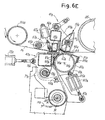
Figs.6A-6J show a sequence of phases of the splicing operation of two web materials, with reference to one of the two heads of the splicing device; -
Figs.6K and6L show two enlargements of theFigs. 6H and6I respectively; -
Fig.7 shows a detail of the clamping bar of the web material against the roller associated with it to hold the head of the web material; and -
Fig.8 shows an enlargement of the second head of the splicing device. -
Figs. 2 to 5 show in different operating positions an unwinder to feed a web material to a processing line downstream, not shown. A splicing device according to the invention is combined with the unwinder. - The unwinder illustrated is particularly suitable to feed sheets or webs of cardboard to produce corrugated cardboard. The structure of the unwinder, indicated as a whole with 1, may be different from that show in the figures, the splicing device of the invention also being suitable for application in unwinders differing in arrangement.
- In the example illustrated, the unwinder has a fixed structure with two pairs of uprights 3 (a single upright of each pair being visible in the drawing) and a pair of crosspieces 5 (of which one is visible in the drawing while the other is disposed behind it). The
crosspieces 5carry guides 7 for a pair of carriages orslides carriage slides means EP-A-1127820 ,US-A-3858819 ,JP-A-7157156 JP-A-1111749 EP-A-968945 US-A-4919353 ,US-A-5004173 . - The
crosspieces 5 have at the top an assembly of rollers defining a supply or festoon of web material for the purposes described hereunder. This assembly of rollers comprises a first fixedroller 13 and a second fixedroller 15, and a pair ofrollers carriage 21 sliding according to the arrow f21 along aguide 23 carried by the crosspieces 25. - With reference now to
Fig.2 , in the phase of operation illustrated here, three reels, indicated with BA, BB and BC, are located on the unwinder. The reel BA is in a central position inside the unwinder, carried bymeans 11A associated with theslide 9A. The reel BA is the one that supplies the web material, indicated with N2, towards the processing line during the phase shown inFig.2 . The web material N2 follows a path defined by a roller 31 (supported with its axis fixed in relation to theslide 9A) and by aroller 33A carried by theslide 9A and oscillating around theaxis 32A of theroller 31, for the purposes to be explained hereunder. The web material N2 is then driven around amotorized drive roller 35 against which apressure roller 37 can press, through the effect of the action of a piston cylinder actuator. The purpose of theroller 35 is to accelerate the web material in the transitory phases to start feed from a new reel, as shall be better explained hereunder, and thepressure roller 37 prevents slipping between the web material and theaccelerator roller 35. Thepressure roller 37 could also be omitted. - Downstream of the
roller 35 the web material forms a festoon being driven around therollers - The reel BB is engaged by
means 11B associated with theslide 9B and is in the preparation phase. This means that the initial edge of the web material N1 wound around said reel is prepared by the operator and fixed to a clamping bar of a head of the splicing device to be subsequently carried to a splicing position at the tail portion of the web material N2 coming from the reel BA. The reel BB will start to unwind when the reel BA comes to an end or in any case when it must be replaced. For example the two reels BA and BB may be reels of different material and replace each other when a change in the production order occurs. - BC indicates a third reel standing by which will start to be used in place of the reel BB in a subsequent phase of processing.
- The splicing device, which forms the specific object of the present invention, comprises two heads each of which is comprised of two portions which may adopt different reciprocal positions. In the
drawing head head head head Fig.8 . - The two
portions respective axes 45A and 45B. For reasons that shall become more apparent hereunder, while theaxis 45A around which theportion 41A of the first head oscillates may be fixed in relation to thecrosspiece 5, the axis 45B of oscillation of theportion 41B of the second head is provided with a translatory movement to move theportion 41B from the position inFigs.2 and3 to the position inFigs.4 and5 . - The oscillatory movement of the two
portions axes 45A, 45B is controlled by a piston-cylinder actuator indicated with 47A for theportion 41A of thehead portion 41B of thehead - The configuration of the
portions Fig.6A , where these two portions are in the reciprocal position adopted by them when the unwinder is in the position inFig.5 , in a phase immediately prior to splicing of a first web material N1 being fed with a second web material N2 standing by. - The
portion 41A of the first head of the splicing device has a movingunit 49A supported around theaxis 45A and the oscillation of which around said axis is controlled by theaforesaid actuator 47A. The movingunit 49A supports oscillatingly around anaxis 51A acounter-pressure member 53A with acylindrical surface 55A, covered with a resilient material, cooperating with theroller 33A that is part of theportion 43A of the splicing head. Thecylindrical surface 53A constitutes a portion of a straight circular cylinder, for example limited to an arc of 10-30°. This makes thecounter-pressure member 53A particularly small in size and allows other members carried by theunit 49A to be placed in an optimum position for their operation, and in a limited space. In particular, the cuttingmember 67A may be placed in close proximity to the axis ofoscillation 51A of thecounter-pressure member 53A. In this way, as shall become apparent from the description hereunder of a splicing sequence of two web materials, the cut of the material may take place extremely close to the edge of the double-sided adhesive strip applied to the new web material and destined to splice together the tail edge of one web material and the leading edge of the other. This is advantageous as - as is known by those skilled in the art - it is advisable for excessively long free edges not to protrude from the edge of the double-sided adhesive strip. Moreover, it is also advisable for the double-sided adhesive strip not to be excessively wide, also in order to reduce the quantity of material used. - As can be seen in particular in
Figs.6A-6L , the cutting member is tilted to form an acute angle with the portion of web material downstream of the cutting point, in relation to the direction of feed of the material. This makes operation of the device more efficient and reliable. In fact, even if the cuttingmember 67A, which is usually a toothed blade, has not cut the web material completely before splicing, subsequent drawing of the material does not cause it to disengage from the teeth of the blade. On the contrary, these teeth hold it until it tears along the line of the cut made by the teeth of the blade. This ensures that the web material of the reel which is running out is in any case severed. - The
axis 45A supports a pair of oscillatingarms 57A carrying acrosspiece 59A with which apad 61A is integral. Themembers pneumatic spring 65A secured at one end to theoscillating arms 57A and at the opposite end to the movingunit 41A. The moving unit 49 also carries a cuttingmember 67A to cut the web material N1. Finally, 69A indicates an adjustable stop secured rigidly to the movingunit 49A. - Again with reference to the parts visible in
Fig.6A , theportion 43A of thehead support 71A, hinged around theaxis 32A of theroller 31 mentioned above, said axis being carried by theslide 9A. The oscillating movement of the movingsupport 71A is controlled by a piston-cylinder actuator 73A hinged in 75A to the movingsupport 71A and in 77A to theslide 9A. Hinged around anaxis 79A carried by thesupport 71A are a pair of oscillatingarms 81A which support theaforesaid roller 33A, the axis of which is indicated with 34A. Associated with the pair of oscillatingarms 81A and consequently with theroller 33A supported idle by said arms is a piston-cylinder actuator 83A, which has the dual function of actuator member and elastic member, as shall become apparent hereunder. The piston-cylinder 83A is secured in 85A to the oscillating arms 81 and in 87A to the movingsupport 71A. Also rigidly secured to theoscillating arms 81A is asection bar 89A defining achannel 91A to trim the initial edge of the web material N2 when it is prepared for subsequent splicing to the web N1. This is a manual operation and is per se known. - The moving
support 71A supports, rigidly secured to it, a clampingbar 93A cooperating with theroller 33A, the structure of which is shown in detail inFig.7 . The clampingbar 93A has a series of pads made of rubber or another elastomer or similar material, indicated with 95A.Elastic plates 97A, made of metal or another suitable material, are inserted between them. The purpose of thepads 95A and theplates 97A is to hold, by pressing against the cylindrical surface of theroller 33A, the leading edge of the web material N2 positioned for splicing with the tail edge of the web material N1. - Disposed above the
pads 95A and theplates 97A is an element parallel to the extension of the clampingbar 93A defining asurface 99A with which thepad 61A of the braking means 63A cooperates to clamp the web material N1 during the phase to cut and splice it with the web material N2. The section bar forming thesurface 99A also defines, together with asection bar 101A, a counter-blade or cuttingchannel 103A cooperating with the cuttingmember 67A carried by the movingunit 49A of theportion 41A of thehead - The second head of the splicing device, formed by the
portions portions Fig.8 , in the position they adopt when the unwinder is in the position inFig.3 ready to splice a web N2 being supplied to a web N1 standing by. Identical or equivalent parts to those of thefirst head
With reference now toFigs.2 to 5 the various positions that the unwinder may adopt are illustrated and subsequently with reference toFigs.6A to 6J the cutting and splicing sequence of the web material N1 and N2 performed by thehead head - As indicated above, in
Fig.2 the unwinder is in an operating phase in which a web material N2 is supplied from the reel BA in the central position towards the corrugated cardboard production line, while the web material N1 is prepared by the operator who trims the initial edge and clamps it on theportion 43B of thehead - For this purpose the
portion 43B of the head of the splicing device has been taken to the position shown inFig.2 moving it along guides 111 carried by thecrosspieces 5. Theroller 33B is moved away from the clampingbar 93B by the piston-cylinder actuator 83B to facilitate insertion by the operator of the leading edge of the web material between the roller and the bar. Once this operation has been performed, the piston-cylinder actuator 83B presses theroller 33B against the clampingbar 93B to hold the web material between the roller and the pads 95B. In this position the operator can trim the web material with a knife cutting it along the cutting channel 91B. In close proximity to the edge obtained by the cut he then applies a strip of double-sided adhesive AA. After the operator has trimmed the initial edge of the web material, and applied the strip of double-sided adhesive material to it, the piston-cylinder actuator 83B moves theroller 33B back slightly from the pads 95B, to an extent that the web material is still held between the roller and the elastic plates 97B. This allows the operator to rotate the reel BB slightly in the rewinding direction until the edge of the web material and the strip of double-sided adhesive material AA are as close as possible to the channel or counter-blade 103B. Upon reaching this position the piston-cylinder actuator 83B is again taken to press thecylinder 33B with greater force against the clampingbar 93B to hold the leading edge of the web material between theroller 33B and the pads 95B. With these operations a free leading edge can be produced, positioned extremely close to the counter-blade 103B and the double-sided adhesive strip can practically be applied to the edge of the material, to obtain a high quality splice. - In the subsequent
Fig.3 it can be seen how the reel BA is still in the operating position. It supplies web material N2 along the path defined above with reference toFig.2 . Its diameter is reduced due to the fact that the web material wound on it has already been partly supplied to the processing line. - Preparation of the leading edge of the web material N1 coming from the reel BB has been terminated and this edge has been carried from the
portion 43B of thehead Fig.3 , close to the delivery zone of the web material towards the processing line. For this purpose theportion 43B of the head of the splicing device has been made to rotate and translate along theguides 111 carried by thecrosspieces 5 of the fixed structure of the unwinder. - When the reel BA has come to an end or in any case must be replaced with the reel BB, the
head head Fig.4 . For this purpose the reel BA that has come to an end is released by themeans 11A carried by theslide 9A to removal means (for example a conveyor belt) disposed in the central zone of the unwinder, under the position of the reel BA inFig.3 . - After the reel BA has been unloaded, the two
slides Fig.4 . Theslide 9A is thus in the position to the right in the drawing to engage the reel BC which is standing by. - The
slide 9B is now in the central position and supports the reel BB from which the web material N1 is now supplied to the production line downstream. The position on the left inFig.4 shows a new reel BD that has been placed in the unwinder. - As can be seen in
Fig.4 , theportion 41B of thehead Fig.4 , so that it does not interfere with theportion 43A of thehead - The
portion 43A of the first head of the splicing device is, in fact, translated from the position inFig.3 to the position inFig.4 being carried by theslide 9A, when this moves from the central position adopted inFig.3 to the side position inFig.4 . - Moreover, in the position in
Fig.4 theportion 43A of thefirst head axis 32A of theroller 31 by the piston-cylinder actuator 73A. - In this position of the
portion 43A of thefirst head means 11A and raised from theconveyor 113. For this purpose, the operations already described with reference toFig.2 and relative to preparation of the free leading edge of the web material N1 of the reel BB are performed by the operator. - In
Fig.5 the unwinder is still in the position inFig.4 except for the different position adopted by theportion 43A of thehead Fig.5 theportion 43A was made to oscillate by the piston-cylinder actuator 73A around theaxis 32A of theroller 31 counter-clockwise to adopt the cutting and splicing position. The reciprocal position of theportions Fig.5 coincides with the position inFig.6A . This is the initial starting position of the splicing and cutting cycle which will now be described with reference to the sequence inFigs. 6A-6J . - In
Fig.6A the web material supplied is again the material N1 coming from the reel BB which is in the central position of the unwinder (Fig.5 ). Thehead accelerator roller 35 carried by the fixedstructure roller 33B which forms part of theportion 43B of thesecond head roller 33B, in this phase, acts as a driving roller for the web material. - The leading edge L of the web material N2 is held between the
roller 33A and the clampingbar 93A. A strip of double-sided adhesive material AA has been applied to the end portion of this edge L in the way described hereinbefore. This strip of double-sided material is in the zone between thebar 93A and the cuttingchannel 91A, defined by thesection bar 89 and along which the operator cut the web material N2. - To cut the material N1 and splice the web materials N1 and N2 the moving
unit 49A performs a clockwise oscillating movement controlled by theactuator 47A.Fig.6B shows how the movingunit 49A has started its oscillating movement, having performed a rotation of about 15° in relation to the position inFig.6A . Thepad 61A of the braking means 63A is now in contact with the web material N1 and pushes it towards thecounter-pressure surface 99A. The feed speed of the web material N1 from the reel to theaccelerator roller 35 is gradually reduced to almost zero with gradual slowing of theroller 35 and braking of the reel to prevent the material from slackening due to inertia of the reel. The speed of the web material downstream of the unwinder, that is the supply speed to the processing line, remains substantially unvaried thanks to the supply accumulated in the festoon defined by therollers - In the position shown in
Fig.6C the movingunit 49A has performed a further clockwise oscillating movement advancing by more or less another 4° around theaxis 45A through the effect of the piston-cylinder actuator control 47A. In this position thepad 61A of the braking means 63A presses the web material N1 against thecounter-pressure surface 99A clamping the web material N1. This is no longer supplied by the reel BB, which stopped previously. Feed of the material N1 to the production line is again guaranteed by the supply accumulated in the festoon defined by the drivingrollers roller 35. - The
slide 21 then moves from left to right (with reference toFigs. 1 to 5 ) to feed the web material towards thedelivery roller 13 and then towards the production line. This guarantees continuous feed and a substantially constant speed towards the machines downstream. - The oscillating movement of the moving
unit 49A can continue thanks to the fact that thearms 57A can oscillate around theaxis 45A against the effect of theelastic member 65A which holds thepad 61A pressed against thecounter-pressure surface 95A. - In
Fig.6D it can be seen how the movingunit 49A has performed a further downwards oscillating movement around theaxis 45A moving thecounter-pressure member 53A towards theroller 33A and the cuttingmember 67A towards the channel or counter-blade 103A. The web material N1 is still clamped. - In
Fig.6E the movingunit 49A is in a position in which the cuttingmember 67A starts to penetrate the channel or counter-blade 103A cutting the web material N1. The cuttingmember 67A may have a serrated cutting edge, that is toothed, and/or inclined to facilitate penetration of the web material 1 and cutting the material. -
Fig.6F shows how clockwise oscillation of the movingunit 49A continues to complete the cut of the web material N1 by the cuttingmember 67A, while thecounter-pressure member 53A is carried with itscylindrical surface 55A to press against the cylindrical surface of theroller 33A. - In
Fig.6G the tail of the web material N1 is pinched between thecounter-pressure member 53A and theroller 33A. It is pressed against the strip of double-sided adhesive material AA, which was previously applied to the free edge L of the web material N2 which is still held between theroller 33A and the clampingbar 93A. - By further continuing clockwise oscillation of the moving
unit 49A, the head of the splicing device adopts the position inFig.6H . It may be observed here that further lowering of the movingunit 49A has caused movement of theroller 33A, due a clockwise oscillation of the supportingarms 81A against the action of the piston-cylinder actuator 83A, which in this phase acts in substance simply as an elastic member. Oscillation of thearms 81A was caused by the thrust exerted by thecounter-pressure member 53A. This oscillation of thearms 81A causes the cylindrical surface of theroller 33A to move away from thepads 95A of the clampingbar 93A, so that the web material N2 can be drawn in movement as described hereunder. - The moving
unit 49A has reached its lowest position, thestops 69A now being in contact with thesupport 71A of theportion 43A of the head. Theoscillating arms 81A supporting theroller 33A are also in their lowest position defined bystops 110A integral with thesupport 71A. Upon reaching this position the supply of web material N1 in the festoon defined by therollers acceleration roller 35 must be made to rotate pressing the pressure roller 37 (if present) against it. - This determines gradual acceleration of the tail of the web material N1 that draws with it the head of the web material N2. If the web material N1 has not been completely cut by the cutting
member 67A, the drawing movement caused by the acceleration imparted by theaccelerator roller 35 causes the tail of the web material N1 to tear and remain engaged by the teeth of the cuttingmember 67A, thanks to the inclination it takes up in this position. - As can be seen in
Figs.6G-6H , thanks to the particular conformation of thecounter-pressure member 53A, which is not constituted by a cylinder, but by a sector of cylinder, the cuttingmember 67A and thechannel 103A are positioned very close to the position in which the strip of double-sided adhesive AA is located. In this way the web material N1 is cut in close proximity to the strip of double-sided adhesive material AA. - The traction exerted on the tail of the material N1 causes the
roller 33A to start rotating clockwise around its axis and the counter-pressure member 53 to oscillate counter-clockwise according to the arrow f53 (Fig.6H ) around its axis ofoscillation 51A. Consequently thecounter-pressure member 53A will move from the position inFig.6H to the position inFig.6I while the tail of web material N1 will gradually leave the splicing zone leaving theroller 33A and drawing with it the free leading edge L of the web material N2 to which this tail adheres thanks to the strip of double-sided adhesive material AA. The pressure exerted by thecounter-pressure member 53A against theroller 33A ensures that the two web materials N1, N2 are joined to each other through the strip of double-sided adhesive AA. Moreover, at least for a portion of its counter-clockwise oscillating movement, thecounter-pressure member 53A holds theroller 33A pressed downwards, allowing the web material N2 to pass under the clampingbar 93A. - Counter-clockwise oscillation of the
counter-pressure member 53A is limited by a stop against abeam 56A uniting the two sides of the movingunit 49A. When thecounter-pressure member 53A has reached the position against thebeam 56A, it no longer holds theroller 33A in a position sufficiently far from thebar 93A to allow the web material N2 to pass between said bar and theroller 33A. The withdrawn position of theroller 33A could be guaranteed as of now by the action of the piston-cylinder 83A which for this purpose is activated promptly to move theroller 33A away from thebar 93A. - Nonetheless, in order to avoid having to activate the piston-
cylinder 83A promptly, according to the embodiment shown anauxiliary stop 70A is provided integral with theportion 41A of thehead Figs.6K and6L , for the sake of clarity of the drawing. - As can be seen in
Fig.6K , when the head of the splicing device is in the position inFig.6H , before thecounter-pressure member 53A starts to oscillate counter-clockwise following the feed of the web material, theauxiliary stop 70A is not in contact with theportion 43A of the head, but is slightly removed from anabutting surface 72A integral with theoscillating supporting arms 81A. - On the contrary, when the
counter-pressure member 53A is in its position of maximum counter-clockwise oscillation, shown inFig.6I (and in the corresponding enlargement inFig.6L ), theauxiliary stop 70A is in contact with theabutment surface 72A and, as theportion 41A of the head is always held in the same angular position inFig. 6H , this means that theroller 33A, carried by the oscillatingarms 81A does not return to press against thepads 95A of the clampingbar 93A, but is at a sufficient distance to allow the web material N2 freedom to advance and theroller 33A to rotate around its axis. Approach of theportion 41B to theauxiliary stop 70A is determined by the elastic thrust of the piston-cylinder actuator 83A, which in this phase still acts as an elastic member. - This position may be maintained even for a very long period of time, during which complete retraction of the piston-
cylinder actuator 83A may be activated with an appropriate delay. This ceases to act as a simple counter-pressure spring and takes theroller 33A, with theoscillating arms 81A supporting it, to a withdrawn position in respect of thebar 93A. - At this point the head of the splicing device can reach the position shown in
Fig.6J . In this figure withdrawal movement of theroller 33A caused by retraction of the piston-cylinder actuator 83A is still in progress; this circumstance is represented by the arrows in the drawing. It should, however, be understood that raising of theportion 41A of thehead cylinder actuator 83A to withdraw theroller 33A has been completed. - When the
portion 41A is raised thecounter-pressure member 53A returns to the initial position with the aid of an elastic return member, for example a spiral spring coaxial to the axis of oscillation, or in another suitable way. The splicing zone between the web material N1 and the web material N2 continues to advance and is now positioned between theroller 33A and theacceleration roller 35. - The position in
Fig.6J differs from the initial position inFig.6A in substance only for the fact that theroller 33A does not press against the clampingbar 93A. In this way, the web material N2 can pass freely through the space between thebar 93A and theroller 33A and supply the production line downstream. It can, however, in the event of need be braked or clamped by activating the piston-cylinder actuator 83A. - As feed of the material N2 from the reel BC has started (
Fig.5 ) theslides Fig.2 . In this position the operator can place the free edge of a new web material on theportion 43B of thehead head Figs.6A-6J performed by thehead - From the description it is apparent how the entire splicing and cutting operation can take place extremely rapidly, therefore allowing the unwinder and production line downstream to reach high production speeds, without the risk during the splicing and cutting operations of the supply of web material contained in the festoon above the reel being unwound coming to an end in advance. Moreover, the structure of the splicing device is particularly simple and hence its operation reliable, thanks to the fact that the entire splicing and cutting cycle is performed operating a single actuator (the
actuator 47A in the case of thehead - It is understood that the drawing only shows an example provided purely as a practical demonstration of the invention, and said invention may vary in forms and arrangements without however departing from the scope of the concept underlying the invention. Any reference numbers in the accompanying claims are provided to facilitate reading of the claims with reference to the description and to the drawing, and do not limit the scope of protection represented by the claims.
Claims (22)
- A splicing device to splice a first web material (N1; N2), coming from a reel being fed (BA; BB; BC; BD), to a second web material (N2; N1), coming from a standing by reel, comprising two heads (41A, 43A; 41 B, 43B), each of which comprises:- a roller (33A; 33B) associated with a clamping bar (93A; 93B) to hold between said roller and said clamping bar an initial edge (L) of the second web material;- a counter-pressure member (53A; 53B) cooperating with said roller to press said first and second web materials against each other;- a cutting member (67A; 67B);characterized in that said counter-pressure member (53A; 53B) and said cutting member (67A; 67B) are carried by a moving unit (49A; 49B) controlled by a single actuator (47A; 47B) which, through the movement it imparts on said moving unit, causes the first and the second web material to be pinched between said roller (33A; 33B) and said counter-pressure member (53A; 53B), the first web material to be cut by said cutting member (67A; 67B) and the second web material to be released by a movement of said roller (33A; 33B) in respect of said clamping bar (93A; 93B), the roller (33A; 33B) being pushed by said counter-pressure member (53A; 53B) and removed from the clamping bar (93A; 93B).
- Splicing device as claimed in claim 1, characterized in that braking means (63A, 63B) are disposed on said moving unit to hold the first web material (N1; N2) during cutting, said actuator also controlling clamping of the first web material through said braking means (63A, 63B).
- Splicing device as claimed in claim 1 or 2, characterized in that the moving unit (49A, 49B) of each of said heads is provided with an oscillating movement around a first axis of oscillation (45A; 45B), controlled by said actuator (47A; 47B).
- Splicing device as claimed in claim 3, characterized in that the counter-pressure member (53A; 53B) of each of said heads is supported by said moving unit (49A; 49B) in an oscillating way around a second axis of oscillation (51A; 51 B), substantially parallel to said first axis of oscillation (45A; 45B), and that said counter-pressure member has a substantially cylindrical surface (55A; 55B) cooperating with said roller (33A; 33B).
- Splicing device as claimed in claim 4, characterized in that said counter-pressure member has a surface (55A; 55B), cooperating with said roller (33A; 33B), constituted by a portion of a straight circular cylindrical surface with axis coinciding with the axis (51A; 51 B) of oscillation of said counter-pressure member.
- Splicing device as claimed in at least claim 2, characterized in that said braking means (63A; 63B) is movably supported on said moving unit (49A; 49B).
- Splicing device as claimed in claim 6, characterized in that said braking means comprise an oscillating arm (57A; 57B) hinged to said moving unit (49A; 49B) around an axis of oscillation (45A; 45B), and that said oscillating arm (57A; 57B) is associated with an elastic member (65A; 65B).
- Splicing device as claimed in claim 7, characterized in that said braking means is hinged around said first axis of oscillation (45A; 45B), around which said moving unit (49A; 49B) oscillates.
- Splicing device as claimed in claim 2, characterized in that said braking means cooperates with a counter-pressure surface (99A; 99B) integral with said clamping bar (93A; 93B).
- Splicing device as claimed in one or more of the previous claims, characterized in that said roller (33A; 33B) is supported by an oscillating arm (81A; 81 B) associated with a stressing member (83A; 83B) which stresses the roller (33A; 33B) against said clamping bar (93A; 93B).
- Splicing device as claimed in claim 10, characterized in that said stressing member (83A; 83B) is a piston-cylinder actuator which acts, at least temporarily, as an elastic stressing member.
- Splicing device as claimed in one or more of the previous claims, characterized in that said moving unit (49A; 49B) is equipped with a stop (69A; 69B) cooperating with a stop surface integral with said clamping bar (93A; 93B), to define a position of maximum approach of said moving unit (49A; 49B) to said clamping bar (93A; 93B).
- Splicing device as claimed in claim 12, characterized in that said moving unit (49A; 49B) is equipped with an auxiliary stop (70A; 70B) cooperating with said oscillating arms (83A; 83B), to hold said roller (33A; 33B) detached from the clamping bar (93A; 93B) when the counter-pressure member (53A; 53B) moves away from its position of maximum approach to the roller.
- Splicing device as claimed in one or more of the previous claims, characterized in that a counter-blade (103A; 103B) cooperating with said cutting member (67A; 67B) is integral with said clamping bar.
- Splicing device as claimed in claim 9 and 14, characterized in that said counter-blade is disposed adjacent to the counter-pressure surface with which said braking means cooperate.
- Splicing device as claimed in one or more of the previous claims, characterized in that said roller (33A; 33B) and said clamping bar (93A, 93B) of each head are carried by a moving support (71A; 71 B) designed to adopt alternately a first operating position, in which the roller (33A; 33B) is in position to cooperate with said counter-pressure member (53A, 53B), and a second position, to allow preparation and clamping of the free edge of the second web material.
- Splicing device as claimed in claim 16, characterized in that said moving support is provided with an oscillating movement.
- Splicing device as claimed in one or more of the previous claims, characterized in that when said cutting member (67A; 67B) is in the position to cut the web material (N 1; N2), it forms, with the direction of feed of the web material, an acute angle.
- Splicing device as claimed in claim 18, characterized in that said cutting member comprises a serrated blade.
- An unwinder comprising means (9A, 9B; 11A, 11B) to support and handle reels (BA; BB; BC; BD) of web material and a splicing device according to one or more of the previous claims.
- Method to splicing together a first web material (N1) and a second web material (N2), comprising the phases of:- arranging a free leading edge (L) of the second web material (N2) on a roller (33A; 33B), clamping it between said roller and a clamping bar (93A; 93B), with a strip of double-sided adhesive material (AA) applied to said free leading edge (L);- arranging a counter-pressure member (53A; 53B) opposite said roller (33A; 33B);- arranging a cutting member (67A; 67B) in the vicinity of said counter-pressure member (53A; 53B);characterized by causing, with a single actuator (47A; 47B):- a movement to approach and press the counter-pressure member (53A; 53B) against said roller (33A; 33B) to pinch between said counter-pressure member and said roller the first web material and the second web material with the strip of double-sided adhesive material between them;- a movement of the cutting member to cut the first web material (N1).
- Method as claimed in claim 21, characterized by arranging a braking means (63A; 63B) in the vicinity of said cutting member (67A, 67B) and causing with said actuator (47A, 47B) a braking movement of said first web material (N1) by means of said braking means (63A, 63B)
Applications Claiming Priority (2)
| Application Number | Priority Date | Filing Date | Title |
|---|---|---|---|
| ITFI20020178 | 2002-09-25 | ||
| IT000178A ITFI20020178A1 (en) | 2002-09-25 | 2002-09-25 | JOINTING MACHINE TO JOIN THEIR TWO TAPE MATERIALS, UNWINDER INCLUDING THE JOINTING MACHINE AND RELATED METHOD |
Publications (4)
| Publication Number | Publication Date |
|---|---|
| EP1422175A2 EP1422175A2 (en) | 2004-05-26 |
| EP1422175A3 EP1422175A3 (en) | 2005-02-02 |
| EP1422175B1 true EP1422175B1 (en) | 2008-08-20 |
| EP1422175B9 EP1422175B9 (en) | 2009-04-08 |
Family
ID=32170726
Family Applications (1)
| Application Number | Title | Priority Date | Filing Date |
|---|---|---|---|
| EP03425616A Expired - Lifetime EP1422175B9 (en) | 2002-09-25 | 2003-09-24 | Splicing device for splicing two web materials together, unwinder comprising said splicing device and relative method |
Country Status (6)
| Country | Link |
|---|---|
| US (1) | US6966961B2 (en) |
| EP (1) | EP1422175B9 (en) |
| AT (1) | ATE405512T1 (en) |
| DE (1) | DE60323038D1 (en) |
| ES (1) | ES2311686T3 (en) |
| IT (1) | ITFI20020178A1 (en) |
Cited By (1)
| Publication number | Priority date | Publication date | Assignee | Title |
|---|---|---|---|---|
| CN105460661A (en) * | 2015-11-30 | 2016-04-06 | 陕西北人印刷机械有限责任公司 | Butt-joint device and butt-joint method for new and old materials of printer |
Families Citing this family (22)
| Publication number | Priority date | Publication date | Assignee | Title |
|---|---|---|---|---|
| ITFI20020178A1 (en) | 2002-09-25 | 2004-03-26 | Fosber Spa | JOINTING MACHINE TO JOIN THEIR TWO TAPE MATERIALS, UNWINDER INCLUDING THE JOINTING MACHINE AND RELATED METHOD |
| ATE429396T1 (en) | 2004-06-18 | 2009-05-15 | Fosber Spa | SPLICING DEVICE FOR CONNECTING TWO WEB MATERIALS, AND A UNWINDER CONTAINING SUCH SPLICING DEVICE |
| ITTO20050823A1 (en) * | 2005-11-21 | 2007-05-22 | Fameccanica Data Spa | DEVICE FOR JUNCTION OF TAPE MATERIAL |
| DE102006037189A1 (en) * | 2006-08-09 | 2008-02-14 | Khs Ag | A method of performing a roll change in a supply unit for feeding a sheet-like sheet to a packaging machine or the like processing machine and supply unit for performing this method |
| IT1392887B1 (en) | 2009-02-24 | 2012-04-02 | Fosber Spa | PLANT FOR THE PRODUCTION OF CORRUGATED CARDBOARD |
| ITFI20090037A1 (en) | 2009-03-04 | 2010-09-05 | Fosber Spa | "PLANT FOR THE PRODUCTION OF CORRUGATED CARDBOARD, HEATING CIRCUIT WITH ENERGY RECOVERY AND ITS METHOD" |
| US8163118B2 (en) * | 2009-06-21 | 2012-04-24 | Jere F. Irwin | Thermoformable web splicer and method |
| ES2365008B1 (en) * | 2011-05-06 | 2012-07-24 | Manuel Torres Martínez | AUTOMATIC PACKAGER FOR SUPPLY OF CONTINUOUS LAMINARY BANDS. |
| DE102014207050A1 (en) * | 2014-04-11 | 2015-10-15 | Bhs Corrugated Maschinen- Und Anlagenbau Gmbh | Splice device |
| DE102015218321A1 (en) | 2015-09-24 | 2017-03-30 | Bhs Corrugated Maschinen- Und Anlagenbau Gmbh | Splicevorrichtung |
| ITUA20162470A1 (en) | 2016-04-11 | 2017-10-11 | Guangdong Fosber Intelligent Equipment Co Ltd | JUNCTION MATERIAL OF JUNCTION MATERIALS, UNWINDER UNDERSTANDING THE JUNCTION DEVICE, AND OPERATING METHOD |
| ITUA20164142A1 (en) * | 2016-06-07 | 2017-12-07 | Guangdong Fosber Intelligent Equipment Co Ltd | ROLLER UNWINDER WITH COIL LOADING AND UNLOADING SYSTEM |
| US10457512B2 (en) | 2016-09-19 | 2019-10-29 | New Era Converting Machinery, Inc. | Automatic lapless butt material splice |
| IT201800005268A1 (en) * | 2018-05-11 | 2019-11-11 | UNWINDER WITH MULTIPLE UNWINDING STATIONS | |
| IT201900013419A1 (en) | 2019-07-31 | 2021-01-31 | Guangdong Fosber Intelligent Equipment Co Ltd | UNWINDER FOR PAPER REELS AND SIMILAR |
| US12479185B2 (en) | 2020-08-31 | 2025-11-25 | Fosber S.P.A. | Plant and method for producing a corrugated board |
| US12612278B2 (en) * | 2022-06-03 | 2026-04-28 | GAMBINI S.p.A. | Unwinder, in particular for unwinding reels of paper, semi-automatic plant comprising such unwinder and process for unwinding reels |
| US12269699B2 (en) | 2022-08-31 | 2025-04-08 | Abzac Canada Inc. | Splicing apparatus and method for a paperboard protective corner manufacturing system |
| US11745970B1 (en) * | 2023-03-03 | 2023-09-05 | Elisa M. Duncan | Automatic sleeving splicer and methods of making and using the same |
| DE102023125195A1 (en) * | 2023-09-18 | 2025-03-20 | Krones Aktiengesellschaft | Device for connecting label tapes |
| EP4699968A1 (en) | 2024-08-20 | 2026-02-25 | FOSBER S.p.A. | Splicer for an unwinder, unwinder comprising the splicer, and corrugated board production line comprising the unwinder |
| US12384641B1 (en) | 2024-12-06 | 2025-08-12 | Elisa M. Duncan | Automatic sleeving splicer comprising moving upper and/or lower tape heads |
Family Cites Families (12)
| Publication number | Priority date | Publication date | Assignee | Title |
|---|---|---|---|---|
| US3858819A (en) | 1972-10-24 | 1975-01-07 | Butler Automatic Inc | Web supply apparatus |
| US3841944A (en) * | 1973-06-26 | 1974-10-15 | Harris Intertype Corp | Web splicing apparatus |
| GB1569886A (en) | 1976-03-03 | 1980-06-25 | Sissons A | Splicing webs of sheet material |
| DE3816224C1 (en) | 1988-05-11 | 1989-12-07 | Bhs-Bayerische Berg-, Huetten- Und Salzwerke Ag, 8000 Muenchen, De | |
| DE3816223A1 (en) * | 1988-05-11 | 1989-11-23 | Bhs Bayerische Berg | DEVICE FOR SPLICING RAILWAYS, ESPECIALLY PAPER RAILWAYS FOR THE PRODUCTION OF CARDBOARD |
| DE68926229T2 (en) | 1989-01-25 | 1996-10-02 | Mitsubishi Heavy Ind Ltd | Connection system for railways |
| DE4013656C2 (en) * | 1990-04-27 | 1994-04-21 | Bhs Bayerische Berg | Device for splicing webs, in particular paper webs for the production of corrugated cardboard |
| US6451145B1 (en) * | 1998-03-09 | 2002-09-17 | Frontier Industrial Technology, Inc. | Web splicing system |
| JP3427355B2 (en) * | 2000-12-14 | 2003-07-14 | 株式会社東京機械製作所 | Drive unit for winding body in splicer |
| ES2234357B1 (en) * | 2002-07-25 | 2006-11-01 | Manuel Torres Martinez | AUTOMATIC LAMINARY BAND PACKAGER FOR CONTINUOUS FEEDING PROCESSES. |
| ITFI20020178A1 (en) | 2002-09-25 | 2004-03-26 | Fosber Spa | JOINTING MACHINE TO JOIN THEIR TWO TAPE MATERIALS, UNWINDER INCLUDING THE JOINTING MACHINE AND RELATED METHOD |
| US6701992B1 (en) * | 2002-09-27 | 2004-03-09 | New Era Converting Machinery, Inc. | Automatic butt splicer for converting machine |
-
2002
- 2002-09-25 IT IT000178A patent/ITFI20020178A1/en unknown
-
2003
- 2003-09-24 ES ES03425616T patent/ES2311686T3/en not_active Expired - Lifetime
- 2003-09-24 US US10/668,160 patent/US6966961B2/en not_active Expired - Lifetime
- 2003-09-24 EP EP03425616A patent/EP1422175B9/en not_active Expired - Lifetime
- 2003-09-24 DE DE60323038T patent/DE60323038D1/en not_active Expired - Lifetime
- 2003-09-24 AT AT03425616T patent/ATE405512T1/en not_active IP Right Cessation
Cited By (2)
| Publication number | Priority date | Publication date | Assignee | Title |
|---|---|---|---|---|
| CN105460661A (en) * | 2015-11-30 | 2016-04-06 | 陕西北人印刷机械有限责任公司 | Butt-joint device and butt-joint method for new and old materials of printer |
| CN105460661B (en) * | 2015-11-30 | 2017-05-31 | 陕西北人印刷机械有限责任公司 | A kind of new old material docking facilities of printing machine and its docking calculation |
Also Published As
| Publication number | Publication date |
|---|---|
| US6966961B2 (en) | 2005-11-22 |
| EP1422175A3 (en) | 2005-02-02 |
| ITFI20020178A1 (en) | 2004-03-26 |
| US20040084133A1 (en) | 2004-05-06 |
| ATE405512T1 (en) | 2008-09-15 |
| EP1422175A2 (en) | 2004-05-26 |
| EP1422175B9 (en) | 2009-04-08 |
| ES2311686T3 (en) | 2009-02-16 |
| DE60323038D1 (en) | 2008-10-02 |
Similar Documents
| Publication | Publication Date | Title |
|---|---|---|
| EP1422175B9 (en) | Splicing device for splicing two web materials together, unwinder comprising said splicing device and relative method | |
| US8011409B2 (en) | Splicing device to join together two web materials, unwinding device comprising said splicing device | |
| US5542622A (en) | Method and machine for producing logs of web material and tearing the web upon completion of the winding of each log | |
| KR101115813B1 (en) | Rewind unwinder device for web-shaped material having a temporary accumulating member for loosened material in the step of reel replacement and related method | |
| JP5933564B2 (en) | Winder and method for producing rolls of web material | |
| US6814123B2 (en) | Method and apparatus for applying a splicing tape to a roll of sheet material | |
| US8215086B2 (en) | Method and device for manufacturing rolls of web material with an outer wrapping | |
| CN1190376A (en) | Rewinder capable of tail sealing | |
| KR20000052387A (en) | Apparatus and method for forming a splice in advancing web of paper | |
| EP1742860B1 (en) | Multifunction unwinding device | |
| JP3653030B2 (en) | Paper splicing device, corrugating machine and paper feeding method | |
| US11390480B2 (en) | Sheet supply device and sheet supply method | |
| EP1173377B1 (en) | Single station continuous log roll winder | |
| US3721396A (en) | Shear cutting batcher apparatus | |
| JP3453350B2 (en) | Continuous unwinding apparatus and continuous unwinding method of web | |
| JP2003276915A (en) | Automatic winding unit switching device | |
| JPH03115044A (en) | Rewound paper automatic preparation device | |
| JP2000335793A (en) | Web splicing apparatus and spliced web generating method | |
| JPH0680285A (en) | Automatic web sheet splicing device | |
| JPH0818735B2 (en) | Web take-up device | |
| JPH0640615A (en) | Web splice device | |
| JPH0818736B2 (en) | Web take-up device | |
| JPH03200655A (en) | Roll sheet automatic finish vg device | |
| JP2001293683A (en) | Long material cutting equipment | |
| HK1014919A (en) | Rewinder incorporating a tail sealer |
Legal Events
| Date | Code | Title | Description |
|---|---|---|---|
| PUAI | Public reference made under article 153(3) epc to a published international application that has entered the european phase |
Free format text: ORIGINAL CODE: 0009012 |
|
| AK | Designated contracting states |
Kind code of ref document: A2 Designated state(s): AT BE BG CH CY CZ DE DK EE ES FI FR GB GR HU IE IT LI LU MC NL PT RO SE SI SK TR |
|
| AX | Request for extension of the european patent |
Extension state: AL LT LV MK |
|
| PUAL | Search report despatched |
Free format text: ORIGINAL CODE: 0009013 |
|
| AK | Designated contracting states |
Kind code of ref document: A3 Designated state(s): AT BE BG CH CY CZ DE DK EE ES FI FR GB GR HU IE IT LI LU MC NL PT RO SE SI SK TR |
|
| AX | Request for extension of the european patent |
Extension state: AL LT LV MK |
|
| 17P | Request for examination filed |
Effective date: 20050621 |
|
| AKX | Designation fees paid |
Designated state(s): AT BE BG CH CY CZ DE DK EE ES FI FR GB GR HU IE IT LI LU MC NL PT RO SE SI SK TR |
|
| GRAP | Despatch of communication of intention to grant a patent |
Free format text: ORIGINAL CODE: EPIDOSNIGR1 |
|
| GRAS | Grant fee paid |
Free format text: ORIGINAL CODE: EPIDOSNIGR3 |
|
| GRAA | (expected) grant |
Free format text: ORIGINAL CODE: 0009210 |
|
| AK | Designated contracting states |
Kind code of ref document: B1 Designated state(s): AT BE BG CH CY CZ DE DK EE ES FI FR GB GR HU IE IT LI LU MC NL PT RO SE SI SK TR |
|
| REG | Reference to a national code |
Ref country code: GB Ref legal event code: FG4D |
|
| REG | Reference to a national code |
Ref country code: CH Ref legal event code: EP |
|
| REG | Reference to a national code |
Ref country code: IE Ref legal event code: FG4D |
|
| REF | Corresponds to: |
Ref document number: 60323038 Country of ref document: DE Date of ref document: 20081002 Kind code of ref document: P |
|
| PG25 | Lapsed in a contracting state [announced via postgrant information from national office to epo] |
Ref country code: NL Free format text: LAPSE BECAUSE OF FAILURE TO SUBMIT A TRANSLATION OF THE DESCRIPTION OR TO PAY THE FEE WITHIN THE PRESCRIBED TIME-LIMIT Effective date: 20080820 |
|
| REG | Reference to a national code |
Ref country code: ES Ref legal event code: FG2A Ref document number: 2311686 Country of ref document: ES Kind code of ref document: T3 |
|
| PG25 | Lapsed in a contracting state [announced via postgrant information from national office to epo] |
Ref country code: SI Free format text: LAPSE BECAUSE OF FAILURE TO SUBMIT A TRANSLATION OF THE DESCRIPTION OR TO PAY THE FEE WITHIN THE PRESCRIBED TIME-LIMIT Effective date: 20080820 Ref country code: AT Free format text: LAPSE BECAUSE OF FAILURE TO SUBMIT A TRANSLATION OF THE DESCRIPTION OR TO PAY THE FEE WITHIN THE PRESCRIBED TIME-LIMIT Effective date: 20080820 Ref country code: FI Free format text: LAPSE BECAUSE OF FAILURE TO SUBMIT A TRANSLATION OF THE DESCRIPTION OR TO PAY THE FEE WITHIN THE PRESCRIBED TIME-LIMIT Effective date: 20080820 |
|
| PG25 | Lapsed in a contracting state [announced via postgrant information from national office to epo] |
Ref country code: BE Free format text: LAPSE BECAUSE OF FAILURE TO SUBMIT A TRANSLATION OF THE DESCRIPTION OR TO PAY THE FEE WITHIN THE PRESCRIBED TIME-LIMIT Effective date: 20080820 |
|
| PG25 | Lapsed in a contracting state [announced via postgrant information from national office to epo] |
Ref country code: MC Free format text: LAPSE BECAUSE OF NON-PAYMENT OF DUE FEES Effective date: 20080930 Ref country code: DK Free format text: LAPSE BECAUSE OF FAILURE TO SUBMIT A TRANSLATION OF THE DESCRIPTION OR TO PAY THE FEE WITHIN THE PRESCRIBED TIME-LIMIT Effective date: 20080820 Ref country code: BG Free format text: LAPSE BECAUSE OF FAILURE TO SUBMIT A TRANSLATION OF THE DESCRIPTION OR TO PAY THE FEE WITHIN THE PRESCRIBED TIME-LIMIT Effective date: 20081120 |
|
| REG | Reference to a national code |
Ref country code: CH Ref legal event code: PL |
|
| PG25 | Lapsed in a contracting state [announced via postgrant information from national office to epo] |
Ref country code: CZ Free format text: LAPSE BECAUSE OF FAILURE TO SUBMIT A TRANSLATION OF THE DESCRIPTION OR TO PAY THE FEE WITHIN THE PRESCRIBED TIME-LIMIT Effective date: 20080820 Ref country code: PT Free format text: LAPSE BECAUSE OF FAILURE TO SUBMIT A TRANSLATION OF THE DESCRIPTION OR TO PAY THE FEE WITHIN THE PRESCRIBED TIME-LIMIT Effective date: 20090120 Ref country code: RO Free format text: LAPSE BECAUSE OF FAILURE TO SUBMIT A TRANSLATION OF THE DESCRIPTION OR TO PAY THE FEE WITHIN THE PRESCRIBED TIME-LIMIT Effective date: 20080820 Ref country code: SK Free format text: LAPSE BECAUSE OF FAILURE TO SUBMIT A TRANSLATION OF THE DESCRIPTION OR TO PAY THE FEE WITHIN THE PRESCRIBED TIME-LIMIT Effective date: 20080820 |
|
| PLBE | No opposition filed within time limit |
Free format text: ORIGINAL CODE: 0009261 |
|
| STAA | Information on the status of an ep patent application or granted ep patent |
Free format text: STATUS: NO OPPOSITION FILED WITHIN TIME LIMIT |
|
| 26N | No opposition filed |
Effective date: 20090525 |
|
| PG25 | Lapsed in a contracting state [announced via postgrant information from national office to epo] |
Ref country code: EE Free format text: LAPSE BECAUSE OF FAILURE TO SUBMIT A TRANSLATION OF THE DESCRIPTION OR TO PAY THE FEE WITHIN THE PRESCRIBED TIME-LIMIT Effective date: 20080820 Ref country code: IE Free format text: LAPSE BECAUSE OF NON-PAYMENT OF DUE FEES Effective date: 20080924 |
|
| PG25 | Lapsed in a contracting state [announced via postgrant information from national office to epo] |
Ref country code: CH Free format text: LAPSE BECAUSE OF NON-PAYMENT OF DUE FEES Effective date: 20080930 Ref country code: LI Free format text: LAPSE BECAUSE OF NON-PAYMENT OF DUE FEES Effective date: 20080930 |
|
| PG25 | Lapsed in a contracting state [announced via postgrant information from national office to epo] |
Ref country code: SE Free format text: LAPSE BECAUSE OF FAILURE TO SUBMIT A TRANSLATION OF THE DESCRIPTION OR TO PAY THE FEE WITHIN THE PRESCRIBED TIME-LIMIT Effective date: 20081120 |
|
| PG25 | Lapsed in a contracting state [announced via postgrant information from national office to epo] |
Ref country code: LU Free format text: LAPSE BECAUSE OF NON-PAYMENT OF DUE FEES Effective date: 20080924 Ref country code: HU Free format text: LAPSE BECAUSE OF FAILURE TO SUBMIT A TRANSLATION OF THE DESCRIPTION OR TO PAY THE FEE WITHIN THE PRESCRIBED TIME-LIMIT Effective date: 20090221 Ref country code: CY Free format text: LAPSE BECAUSE OF FAILURE TO SUBMIT A TRANSLATION OF THE DESCRIPTION OR TO PAY THE FEE WITHIN THE PRESCRIBED TIME-LIMIT Effective date: 20080820 |
|
| PG25 | Lapsed in a contracting state [announced via postgrant information from national office to epo] |
Ref country code: TR Free format text: LAPSE BECAUSE OF FAILURE TO SUBMIT A TRANSLATION OF THE DESCRIPTION OR TO PAY THE FEE WITHIN THE PRESCRIBED TIME-LIMIT Effective date: 20080820 |
|
| PG25 | Lapsed in a contracting state [announced via postgrant information from national office to epo] |
Ref country code: GR Free format text: LAPSE BECAUSE OF FAILURE TO SUBMIT A TRANSLATION OF THE DESCRIPTION OR TO PAY THE FEE WITHIN THE PRESCRIBED TIME-LIMIT Effective date: 20081121 |
|
| REG | Reference to a national code |
Ref country code: FR Ref legal event code: PLFP Year of fee payment: 13 |
|
| REG | Reference to a national code |
Ref country code: FR Ref legal event code: PLFP Year of fee payment: 14 |
|
| REG | Reference to a national code |
Ref country code: FR Ref legal event code: PLFP Year of fee payment: 15 |
|
| REG | Reference to a national code |
Ref country code: FR Ref legal event code: PLFP Year of fee payment: 16 |
|
| PGFP | Annual fee paid to national office [announced via postgrant information from national office to epo] |
Ref country code: GB Payment date: 20220920 Year of fee payment: 20 Ref country code: DE Payment date: 20220927 Year of fee payment: 20 |
|
| PGFP | Annual fee paid to national office [announced via postgrant information from national office to epo] |
Ref country code: FR Payment date: 20220926 Year of fee payment: 20 |
|
| PGFP | Annual fee paid to national office [announced via postgrant information from national office to epo] |
Ref country code: IT Payment date: 20220928 Year of fee payment: 20 Ref country code: ES Payment date: 20221013 Year of fee payment: 20 |
|
| P01 | Opt-out of the competence of the unified patent court (upc) registered |
Effective date: 20230519 |
|
| REG | Reference to a national code |
Ref country code: DE Ref legal event code: R071 Ref document number: 60323038 Country of ref document: DE |
|
| REG | Reference to a national code |
Ref country code: ES Ref legal event code: FD2A Effective date: 20230929 |
|
| REG | Reference to a national code |
Ref country code: GB Ref legal event code: PE20 Expiry date: 20230923 |
|
| PG25 | Lapsed in a contracting state [announced via postgrant information from national office to epo] |
Ref country code: GB Free format text: LAPSE BECAUSE OF EXPIRATION OF PROTECTION Effective date: 20230923 Ref country code: ES Free format text: LAPSE BECAUSE OF EXPIRATION OF PROTECTION Effective date: 20230925 |