EP1422151A1 - Carton opening feature - Google Patents
Carton opening feature Download PDFInfo
- Publication number
- EP1422151A1 EP1422151A1 EP03257358A EP03257358A EP1422151A1 EP 1422151 A1 EP1422151 A1 EP 1422151A1 EP 03257358 A EP03257358 A EP 03257358A EP 03257358 A EP03257358 A EP 03257358A EP 1422151 A1 EP1422151 A1 EP 1422151A1
- Authority
- EP
- European Patent Office
- Prior art keywords
- carton
- door
- panel
- opening
- weakness
- Prior art date
- Legal status (The legal status is an assumption and is not a legal conclusion. Google has not performed a legal analysis and makes no representation as to the accuracy of the status listed.)
- Withdrawn
Links
- 230000000903 blocking effect Effects 0.000 claims abstract description 55
- 238000000034 method Methods 0.000 claims description 12
- 238000006073 displacement reaction Methods 0.000 claims description 6
- 230000007423 decrease Effects 0.000 claims description 3
- 239000011087 paperboard Substances 0.000 description 17
- 239000010410 layer Substances 0.000 description 14
- 239000002344 surface layer Substances 0.000 description 8
- 235000013351 cheese Nutrition 0.000 description 7
- 235000015067 sauces Nutrition 0.000 description 7
- 238000004806 packaging method and process Methods 0.000 description 6
- 238000000926 separation method Methods 0.000 description 5
- 235000015927 pasta Nutrition 0.000 description 4
- 239000000853 adhesive Substances 0.000 description 3
- 230000001070 adhesive effect Effects 0.000 description 3
- 210000003811 finger Anatomy 0.000 description 3
- 238000004026 adhesive bonding Methods 0.000 description 2
- 230000007246 mechanism Effects 0.000 description 2
- 238000012986 modification Methods 0.000 description 2
- 230000004048 modification Effects 0.000 description 2
- 238000012856 packing Methods 0.000 description 2
- 238000003825 pressing Methods 0.000 description 2
- 238000003860 storage Methods 0.000 description 2
- 235000013339 cereals Nutrition 0.000 description 1
- 239000011248 coating agent Substances 0.000 description 1
- 238000000576 coating method Methods 0.000 description 1
- 238000010276 construction Methods 0.000 description 1
- 238000005520 cutting process Methods 0.000 description 1
- 230000000994 depressogenic effect Effects 0.000 description 1
- 238000009826 distribution Methods 0.000 description 1
- 239000002355 dual-layer Substances 0.000 description 1
- 235000013305 food Nutrition 0.000 description 1
- 239000003292 glue Substances 0.000 description 1
- 238000004519 manufacturing process Methods 0.000 description 1
- 239000000463 material Substances 0.000 description 1
- 235000012054 meals Nutrition 0.000 description 1
- 230000002787 reinforcement Effects 0.000 description 1
- 238000007789 sealing Methods 0.000 description 1
- 210000003813 thumb Anatomy 0.000 description 1
- 230000000007 visual effect Effects 0.000 description 1
Images
Classifications
-
- B—PERFORMING OPERATIONS; TRANSPORTING
- B65—CONVEYING; PACKING; STORING; HANDLING THIN OR FILAMENTARY MATERIAL
- B65D—CONTAINERS FOR STORAGE OR TRANSPORT OF ARTICLES OR MATERIALS, e.g. BAGS, BARRELS, BOTTLES, BOXES, CANS, CARTONS, CRATES, DRUMS, JARS, TANKS, HOPPERS, FORWARDING CONTAINERS; ACCESSORIES, CLOSURES, OR FITTINGS THEREFOR; PACKAGING ELEMENTS; PACKAGES
- B65D5/00—Rigid or semi-rigid containers of polygonal cross-section, e.g. boxes, cartons or trays, formed by folding or erecting one or more blanks made of paper
- B65D5/42—Details of containers or of foldable or erectable container blanks
- B65D5/70—Break-in flaps, or members adapted to be torn-off, to provide pouring openings
- B65D5/701—Tearable flaps defined by score-lines or incisions provided in the closure flaps of a tubular container made of a single blank
- B65D5/703—Tearable flaps defined by score-lines or incisions provided in the closure flaps of a tubular container made of a single blank the score-lines or incisions extending in the body of the tubular container
-
- B—PERFORMING OPERATIONS; TRANSPORTING
- B65—CONVEYING; PACKING; STORING; HANDLING THIN OR FILAMENTARY MATERIAL
- B65D—CONTAINERS FOR STORAGE OR TRANSPORT OF ARTICLES OR MATERIALS, e.g. BAGS, BARRELS, BOTTLES, BOXES, CANS, CARTONS, CRATES, DRUMS, JARS, TANKS, HOPPERS, FORWARDING CONTAINERS; ACCESSORIES, CLOSURES, OR FITTINGS THEREFOR; PACKAGING ELEMENTS; PACKAGES
- B65D5/00—Rigid or semi-rigid containers of polygonal cross-section, e.g. boxes, cartons or trays, formed by folding or erecting one or more blanks made of paper
- B65D5/42—Details of containers or of foldable or erectable container blanks
- B65D5/54—Lines of weakness to facilitate opening of container or dividing it into separate parts by cutting or tearing
- B65D5/5405—Lines of weakness to facilitate opening of container or dividing it into separate parts by cutting or tearing for opening containers formed by erecting a blank in tubular form
- B65D5/542—Lines of weakness to facilitate opening of container or dividing it into separate parts by cutting or tearing for opening containers formed by erecting a blank in tubular form the lines of weakness being provided in the container body
- B65D5/544—Lines of weakness to facilitate opening of container or dividing it into separate parts by cutting or tearing for opening containers formed by erecting a blank in tubular form the lines of weakness being provided in the container body and defining after rupture a lid hinged about a line located in the top surface of the container
Definitions
- the apparatus and methods described herein relate generally to a carton, and particularly to a carton having an opening feature allowing access to an interior of the carton.
- Cartons are often used as packaging for a variety of consumer products.
- the carton may be configured for opening by the consumer for removal of the contents from the interior thereof.
- the marketing, distribution and sale of contents packaged in cartons for consumers often requires considerable attention to the design of the cartons used to package such products.
- One type of carton is provided with a pair of overlapping flaps or panels on one end that are attached relative to each other. Often, the overlapping panels are merely glued together, requiring the consumer to break the glue bonding the two overlapping panels to gain access to the interior of the carton. Considerable effort may be required by the consumer to break the adhesive bonding between the panels, and can result in uncontrolled tears in the carton. To address these concerns, some cartons have been provided with a tear strip between the overlapping panels, allowing a consumer to remove the tear strip to allow the panels to separate in order to gain access to the interior of the carton.
- Perforated regions for opening cartons may be located at various parts of the carton, such as upper portions of a side panel or on the top panel of the carton. After opening of the perforated regions, such regions may be designed to remain connected to the carton wall by a hinge so that the perforated region is not detached from the carton.
- perforated regions are found in existing carton designs for paperboard cartons.
- the perforated regions may be bordered by a series of perforations, reverse cuts, score lines, or cut lines in the surface of a carton wall in the shape of a "V", a "U", an oval, a rectangle or other shapes.
- the carton is opened by pressing the perforated region toward the interior of the carton so that the carton wall ruptures or tears along the perforations to form an opening allowing access to the interior of the carton.
- the open perforated region may be configured to act as a finger grip that allow the user to create a larger opening in the carton.
- the perforated region can first be depressed into the interior of the carton by the consumer. Next, the consumer can pull on the perforated region, such as toward a side or top of the carton, to peel back a panel of the carton and to create an enlarged opening permitting improved access to the contents of the carton. In some cartons, the carton side or top panel may be removed entirely.
- a perforated region as described above to provide an opening for further opening the carton may be employed in cartons for bulk products such as pastas, cereals and similar food stuffs. Often sauce packets or other flavoring packets are provided with the bulky, pourable products. The removal of such packets can be difficult when the bulk contents shift during shipping and handling prior to opening by a consumer. When a consumer finally opens the carton, the bulk contents and the packets may have shifted in a manner to cause difficulty in removing the bulk contents and the packets from the interior of the carton. In some instances, the packets can even block the openings of the carton, further causing difficulty in removing the bulk contents.
- carton opening features requires consideration of a number of objectives and performance requirements in addition to providing for convenient opening of the carton by a consumer.
- the easy open features in such cartons should not compromise the structural integrity and strength of the carton.
- Paperboard cartons often are subjected to a variety of loads and stress during shipping, storage, and handling of the cartons. These include stresses and loads experienced during the packing of individual cartons in shipping cases, in palletizing the cases for storage at warehouse facilities, and during shipment, stacking, and other movement of pallets. Once the cartons reach a retailer, they may be subjected to additional stresses and loads during the shelving and display of the product. Consumers purchasing such cartons may further subject the cartons to stresses and loads that can cause unintentional openings or deformation of the carton.
- Cartons are typically made from a precut, unitary blank having prescored lines that permit the folding, forming, filling and sealing of the cartons using automated machinery.
- an easy open design must be integrated into the overall carton structure with a minimum of complicated or added components.
- the easy open features in paperboard cartons frequently must be integral to a unitary paperboard blank used to form the carton to simplify assembly of the carton and reduce material and assembly costs. It is desirable to avoid the need for unnecessary panels, folds, glues, inserts, reinforcements or the like to form the easy open feature to reduce the cost of the carton and the steps needed to form the carton.
- New improved apparatus and methods are provided for opening a carton to gain access to an interior of the carton and any contents therein. This is achieved by using a carton opening feature which may comprise a gripping tab operably connected to a door for shifting the door from a closed position to an open position. A blocking member is provided that restricts unintentional movement of the gripping tab and thus opening of the door until the door is initially shifted to the open position.
- the carton may be defined by a plurality of panels, including a first panel and a second panel adjacent the first panel.
- the first panel has a window opening formed therein.
- the second panel has a door openable to provide access to the interior of the carton.
- An end of the door has an operably connected gripping tab at least partially accessible through the window of the first panel. The tab allows for reopening of the door to permit access to the interior of the carton.
- the window opening may be surrounded by the first panel, and a portion of the gripping tab of the door may be disposed behind the first panel to both prevent inadvertent opening of the carton and to generally protect the gripping tab from displacement during packaging, shipping, and handling of the carton.
- An end of the door opposite the end having the gripping tab may be pivotably attached by a hinge to the second panel.
- a pair of side edges of the door may each be removably attached to the second panel along an area of weakness.
- the spacing between the areas of weakness may decrease between the end of the door having the gripping tab and the opposite end of the door hinged to the second panel.
- each of the areas of weakness may comprise an inner partial cut and an outer partial cut.
- the inner partial cuts may be formed in the side of the panels facing the interior of the carton, and the outer partial cuts may be formed in the side of the panel facing away from the interior of the carton.
- a blocking portion of the first panel is disposed adjacent the window opening between the window opening and the second panel.
- the blocking portion can hinder inadvertent displacement of the gripping tab, such as during packaging, shipping, and handling.
- the blocking portion can restrict unintentional opening of the door by substantially preventing movement of the gripping member to shift the door to the open position unless the blocking member is removed.
- the blocking portion of the first panel is separable from the remainder of the first panel along one or more lines of weakness.
- the window may include a region having an increasing width adjacent the lines of weakness to facilitate controlled propagation of tears beginning along portions of the lines of weakness adjacent the opening. The region of increasing width may be aligned with the areas of weakness of the blocking portion.
- the areas of weakness may comprise partial inner cuts extending diagonally from the region of increased width of the window opening to at least one of the edges of the first panel.
- the cut may extend from the opening to the side edge of the first panel, the inner section of the upper edge and the side edge of the first panel or the upper edge of the first panel.
- an opening feature for a carton to permit access to an interior of the carton.
- the opening feature includes a door selectively shiftable from a closed position whereby access is restricted to the interior of the carton to an open position whereby access is allowed to the interior of the carton.
- a pull member is operably connected to the door by an intermediate connection element. The pull member has a first state when the door is in the closed position and a second state when the door is in the open position. Movement of the pull member from the first state to the second state shifts the door to its open position.
- a blocking element is provided to cover at least a portion of the intermediate connection element in order to restrict unintentional displacement, such as during shipping and handling, of the intermediate connection element and the pull member prior to movement of the pull member from the first state to the second state for shifting the door to the open position.
- a joint may be provided between the blocking element and the carton to allow for detachment of the blocking element relative to the carton.
- the joint may comprise one or more lines of weakness between the blocking element and the carton.
- the line of weakness may be breakable when the pull element is moved from its first state to its second state allowing the blocking element to move relative to the carton.
- the blocking element may be adjacent an opening in an outer wall of the carton. At least a portion of the pull member may be accessible through the opening.
- the door may be integrally formed in an access wall of the carton.
- the door In the closed position, the door may be connected to the access wall of the carton by one or more joints each comprising a line of weakness.
- the lines of weakness may be breakable when the door is shifted from the closed position to the open position, allowing the door to separate from the access wall to permit access to the interior of the carton.
- the joint may comprise one or more pairs of lines of weakness extending along side edges of the door from an end of the door to a hinge between the access wall and the door.
- the door may be openable with respect to the access wall about the hinge when shifted from the closed position to the open position.
- the access wall may be adjacent to the outer wall of the carton.
- the carton may be generally rectangular in shape.
- a generally rectangular carton having an interior.
- the carton includes a top panel and a bottom panel opposite the top panel.
- One of the top and bottom panels has a door for selectively permitting access to the interior of the carton through an access opening.
- the door has a closed position substantially blocking the access opening and an open position permitting access to the interior of the carton through the access opening.
- a hinge is provided to connect a first end of the door to the one of the top and bottom panels.
- a second end of the door is operably connected to a gripping tab by a tab panel for shifting the door from the closed position to the opened position.
- a carton also includes a pair of side panels. Each side panel extends between edges of the top and bottom panels.
- the carton further includes a front panel extending between edges of the top, bottom and side panels, and a back panel opposite the front panel also extending between edges of the top, bottom and side panels.
- a blocking portion may be provided that is detachably connected to the one of the side panels.
- the blocking portion may cover at least a portion of the tab panel restricting unintentional movement of the gripping tab to hinder inadvertent shifting of the door from the closed position to the open position.
- the blocking portion may be detachably connected to the one of the side panels.
- the door may be detachably connected to the one of the top and bottom panels along a pair of lines of weakness, each disposed on opposite side edges of the door and extending between the ends of the door in the closed position. The lines of weakness are rupturable to separate the door from the one of the top and bottom panels permitting shifting of the door from the closed position to the open position.
- a method of opening a carton comprises providing a pair of adjacent panels. One of the adjacent panels has an opening and the other of the adjacent panels has a door with a door opening portion. The method further comprises lifting a pull tab of the door opening portion. The pull tab may be at least partially aligned within the opening. The method further comprises pulling the pull tab of the door opening feature to separate a border of the opening from the one of the adjacent panels. The method further comprises opening the door by pulling the pull tab of the door opening feature.
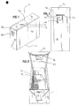
- FIGURES 1-4 there is illustrated an embodiment which generally comprises a carton 10 formed of multiple panels.
- One of the panels 70 has a door 72 that is shiftable from a closed position to an open position to permit access to an interior of the carton 10.
- the door 72 includes a gripping tab 84 at one end that facilitates the initial shifting of the door 72 from the closed position to the open position upon movement of the gripping tab 84.
- the gripping tab 84 is restricted from movement by a blocking member 46 formed on a panel 40 adjacent to the panel 70 having the door 72.
- the blocking member 46 substantially restricts inadvertent opening of the door 72 and deformation of the gripping tab 84 prior to use in opening the door 72, such as during packaging, shipping, and handling. Upon sufficient movement of the gripping tab 84, the blocking member 46 can be detached from the panel 40 adjacent to the panel 70 having the door 72 to permit further movement of the gripping tab 84 to shift the door 72 from the closed position to the open position thereof for permitting access to the interior of the carton 10.
- a door 72 is positioned on the top panel 70 of the carton 10 for providing access to the interior of the carton 10.
- the door 72 is shiftable from an initial, closed position, as illustrated in FIGURE 1, to an open position, as illustrated in FIGURE 3.
- One end of the door 72 is pivotably connected to the top panel 70 about a hinge 74.
- the other end of the door 72 has an attached upper minor flap 82 with a gripping tab 84 depending therefrom. Movement of the gripping tab 84 thus urges the door 72 to pivot about the hinge 74 to shift the door 72 from the closed position to the open position to permit access to the interior of the carton 10.
- the door 72 is integrally formed with the top panel 70. As discussed above, one of the ends of the door 72 is connected to the top panel 70 about a hinge 74 and the other of the ends has the attached upper minor flap 82 and the gripping tab 84. Lateral edges of the door 72 are each joined to the top panel 70 along areas of weakness 75 rupturable to permit separation of the lateral edges of the door 72 from the top panel 70 for shifting the door 72 to the open position.
- the gripping tab 84 and the upper minor flap 82 are positioned partially beneath one of the side panels 40.
- the window opening 42 is formed in the one of the side panels 40 and is positioned so that at least a portion of the gripping tab 84 is accessible through the opening 42 prior to initially shifting the door 72 from its closed position to its open position.
- the window 42 is preferably sized to allow a consumer to access the gripping tab 84 therethrough, such as with fingers, for opening the door 72.
- the window opening 42 is preferably bordered on all sides by the side panel 40.
- the blocking member 46 is integrally formed with the side panel 40 of the carton 10, as illustrated in FIGURE 2, and is preferably the upper border of the window opening 42.
- the blocking member 46 is detachably connected to the remainder of the first panel 40 along a pair of lines of weakness 48 to allow for the gripping tab 84 to initially shift the door 72 from the closed position to the open position.
- the blocking member 46 is positioned to generally protect the gripping tab 84 from substantial displacement and deformation during packaging, shipping, and handling to ensure proper opening of the carton 10 by a consumer. To this end, the blocking member 46 is placed over a portion of the gripping tab 84 so that gripping tab 84 preferably does not protrude beyond the side panel 40 having the window opening 42.
- the window 42 defines a recess having a depth greater than or equal to the thickness of the gripping tab 84.
- the blocking member 46 is secured relative to the upper minor side panel 82 having the gripping tab 84 such that when the blocking member 46 is separated from the outer side panel 40 it remains attached to the upper minor side panel 82 so as to not generate a separate piece of the carton 10 which must be disposed independently of the carton 10 after the contents have been removed therefrom.
- the lines of weakness 48 extend from the window opening 42 to edges of the side panel 40 such that when the gripping tab 84 is moved for shifting the door 72 from the closed position to the open position the blocking member 46 separates from the remainder of the side panel 40 along the lines of weakness 48.
- the lines of weakness 48 comprise perforations, although partial reverse cuts made on the inner side of the side panel 40 may also be used.
- the lines of weakness 48 preferably each extend from the window opening 42 diagonally to a corner of the side panel 40 proximate the door 72 to facilitate shifting of the door 72 to the open position.
- the upper minor panel 82 has side edges 86 with an angle generally corresponding to the angle of the lines of weakness 48.
- the gripping tab 84 is moved a sufficient distance and with a sufficient force, the side edges 86 of the upper minor panel 82 press against the lines of weakness 48 to break the lines of weakness 48 and allow the blocking member 46 to separate from the outer side panel 40.
- the paperboard forming the carton 10 has two layers 92 and 94.
- the first or base layer 94 faces the interior of the carton 10.
- the second or surface layer 92 is disposed on top of the base layer 94 facing the exterior of the carton 10.
- the surface layer 92 has a semi-glossy coating to enhance the appearance of the carton 10.
- the surface layer 92 may have indicia printed thereon to identify the contents of the carton 10 or the brand of the contents.
- the areas of weakness 75 formed on the top panel to allow the door 72 to separate therefrom each comprise two parallel lines of weakness 76 and 78.
- the inner pair 76 of the lines of weakness preferably comprise partial reverse cuts in the paperboard.
- the inner pair 76 of the lines of weakness are preferably continuous, unbroken cuts through at least a portion of the base layer 94 of the paperboard, thereby allowing the base layer 94 to separate from the surface layer 92 along the cuts 76.
- the outer pair 78 of the lines of weakness comprise partial cuts in the paperboard.
- the outer pair 78 of the lines of weakness are broken partial cuts through at least a portion of the surface layer 92, thereby allowing. the surface layer 92 to separate from the base layer 94 along the cuts 78.
- the door 72 When the door 72 is initially shifted from its closed position to its open position it separates from the top panel 70 along both the inner and outer lines of weakness 76 and 78, as best illustrated in FIGURE 3. More specifically, the outer pair of cuts 78 allows the surface layer 92 of the paperboard forming the door 72 to separate from the surface layer 92 of the paperboard forming the top panel 70. Similarly, the inner pair of reverse cuts 76 allows the base layer 94 of the paperboard forming the door 72 to separate from the base layer 94 of paper board forming the top panel 70. In this manner, the initial opening of the door 72 along the areas of weakness is controlled to minimize deviation of the tear from between the inner and outer cuts 76 and 78 on each side of the top surface 92.
- various aspects of the carton 10 are configured to facilitate the initial shifting of the door 72 from the closed position to the open position.
- the spacing between the areas of weakness 75 decreases from where the upper minor flap 82 having the gripping tab 84 meets the front end of the door 72 to the hinge 74.
- the areas of weakness 75 each comprising the generally parallel pair of lines of weakness 76 and 78, begin at the intersection of the front end of the door 72 with the upper minor panel 82 and extend to the hinge 74 between the door 72 and the top panel 70.
- the inner pair of the lines of weakness 76 begin at the intersection of the front end of the door 72 with the upper minor flap 82 and are spaced a distance inward from lateral edges of the top panel 70.
- the outer pair 78 of the lines of weakness are parallel to the inner pair 76 of the lines of weakness, except at the intersection of the front end of the door 72 with the upper minor panel 82.
- the outer pair 78 of the lines of weakness each have a portion 79 extending at a diagonal to the corners of the lateral edges of the top panel 70.
- the initial shifting of the door 72 from the closed position to the open position along the diagonal portion 79 can cause the tear to propagate from the corners of the lateral edges of the top panel 70 to minimize the likelihood of deviation of the tear from the lines of weakness 76 and 78 because, due to a fold between the upper minor panel 82 and the door 72, the corners represent a preweakened area susceptible to tearing.
- the upper minor panel 82 is configured to control the tear between the door 72 and the top panel 70 and ensure that the tear propagates along the areas of weakness 75. More particularly, the intersection between the upper minor panel 82 and the top panel is configured so that the tear begins at the intersection between the corners of the top panel 70 adjacent the upper minor panel 82 along the diagonal portions 79 of the outer lines of weakness 78. To this end, the diagonal edges 86 of the upper minor panel 82 do not continue to the intersection of the upper minor panel 82 and the top panel 70. Instead, corner elements 88 are provided along the upper end of the upper minor panel 82 adjacent the top panel 70. The corner elements 88 give the upper minor panel 82 a short region having a width nearly the same as the width of the top panel 70 to reduce the likelihood of the tear beginning to propagate at a location other than along the diagonal portions 79.
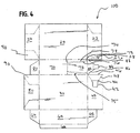
- the container or carton 10 is assembled from a carton blank 100, as illustrated in FIGURE 4.
- the carton blank 100 may be cut from a paperboard sheet using a die cutting machine.
- the paperboard sheet may comprise multiple. layers, including a bottom layer 94 and a top layer 92, as discussed in detail above.
- the carton blank 100 includes a rectangular front panel 20 having a pair of larger side edges and a pair of smaller side edges. One of the pair of the larger side edges of the front panel 20 is connected to the top panel 70 about a fold line. Each of the smaller side edges of the front panel 20 are connected to inner side panels 22 and 24 about fold lines.
- the top panel 70 which includes the door 72, also is rectangular in shape, having a pair of larger edges and a pair of smaller edges.
- a fold between the front panel 20 and the top panel 70 connects one of the larger edges of the front panel 20 with one of the larger edges of the top panel 70.
- a pair of upper minor flaps 80 and 82 are each connected about a fold line to one of the smaller side edges of the top panel 70.
- One of the upper minor flaps 82, connected to the door 72 has angled side edges 86, as discussed in more detail above, and includes the gripping tab 84 at an end thereof opposite the connection of the one of the upper minor flaps 82 with the top panel 70.
- the back panel 30 Connected about a fold to the one of the larger side edges of the top panel 70 opposite the fold connecting the front panel 20 and the top panel 70 is the back panel 30.
- the back panel 30 is also rectangular, having the same dimensions as the front panel 20, including a pair of larger side edges and a pair of smaller side edges.
- the fold between the top panel 70 and the back panel 30 connects the larger side edges of each.
- a pair of outer side panels 40 and 50 are connected to the smaller edges of the back panel 30.
- one of the side panels 40 has a window opening 42 formed therein for providing access to the gripping tab 84 when the blank 100 is assembled into the carton 10.
- a bottom panel 60 is connected by a fold to one of the larger edges of the back panel 30 opposite the fold between the top panel 70 and the back panel 30.
- the bottom panel 60 is rectangular and is dimensioned similar to the top panel 70, including a pair of larger side edges and a pair of smaller side edges.
- minor bottom side panels 62 and 64 are connected via a fold.
- a bottom joint panel 66 is connected along the one of the larger edges of the bottom panel 60 opposite the back panel 30, the purpose of which will be more fully explained below.
- the front panel 20, the top panel 70, the back panel 30, and the bottom panel are folded perpendicularly relative to their adjacent panel.
- the bottom joint panel 66 is then folded perpendicularly relative to the bottom panel 60 and placed against the inside surface of the front panel proximate the larger side edge opposite the top panel 70.
- Adhesive or other bonding mechanisms may be placed between the bottom joint panel 66 and the inside surface of the front panel 20 to secure the bottom joint panel 66 relative to the front panel 20 to form an intermediate stage in the assembly of the carton 10 whereby the carton 10 is partially formed and has a pair of open ends.
- the end having the opening feature is preferably closed in the same order as the end not having the opening feature. More specifically, in order to provide the gripping tab 84 within the window opening 42 of the side panel 40, the closing of the end having the opening feature involves first folding the inner side panel 22 inward and perpendicularly relative to the front panel 20. Next, the upper and lower minor flaps 62 and 82 are folded against the inner side panel 22. Finally, the outer side panel 40 is folded inward against the upper and lower minor panels 62 and 82. Similarly, in closing the end lacking the opening feature, the inner side panel 24 is folded inward.
- the upper and lower minor panels 64 and 80 are first folded inward against the inner side panel 24 and perpendicularly relative to the front panel 20. Finally, the outer side panel 50 is folded against the inner side panel 24 with the upper and lower minor panels 64 and 80 therebetween. Adhesive or other bonding mechanisms may be provided to secure the panels relative to each other to complete assembly of the carton 10. During these carton blank 100 assembly steps, the product can be inserted through one of the ends prior to closing, although other ways of inserting the product into the carton 10 during assembly of the carton blank 100 may be equally suitable.
- the inner and outer side panels 24 and 50 are provided with embossed regions 90 to provide for nesting of the bottom minor panel 64 therebetween.
- the embossed regions 90 comprise stamped areas that allow for the region 90 to move either inwardly or outwardly with respect to the panel 24 or 50.
- embossed region 90 on the inner side panel 24 can move inwardly while the embossed region 90 on the outer side panel 50 can move outwardly when the bottom minor panel 64 is placed therebetween.
- embossed regions 90 are provided between the inner and outer panels 24 and 50 and the upper minor flap 80, as well as the inner and outer side panels 22 and 40 and the bottom minor panel 62. While the inner panel 22 adjacent the upper minor panel 82 having the gripping tab 84 has an embossed region 90, the outer panel 40 lacks an embossed region 90 so as to not interfere with the window opening 42 and removable blocking member 48.
- the upper minor panel 82 having the gripping tab 84 may lack adhesive for bonding the panel 82 relative to the adjacent inner panel 22.
- the bond may be between a perforated portion 26 of the inner panel 22 and the upper minor panel 82.
- the gripping tab 84 is moved with sufficient force and a sufficient distance to separate the blocking member 46 from the outer side panel 40 having the window opening 42, the perforated portion 26 is separable from the inner side panel 22 along lines of weakness 28, and preferably along a perforation cut.
- the perforated portion 26 has shape selected to facilitate separation along the lines of weakness 28 from the inner side panel 22. The shape may include one or more round regions along the bottom where the tear can easily begin to propagate.
- the carton 10 is sized to contain a prepackaged macaroni and cheese kit.
- the kit includes a quantity of macaroni or shells pasta and a cheese sauce pack.
- the cheese sauce pack is placed below the door 72 so that when the door 72 is opened the cheese sauce pack can be withdrawn.
- the door 72 is dimensioned to accommodate withdrawal of the cheese sauce pack through the opening formed after the door 72 is initially shifted from its closed position to its open position. More specifically, the door 72 is between about 2.75 inches and 3.25 inches [about 6.99 cm and 8.26 cm] long, and more preferably is about 3 inches [about 7.62 cm] long.
- the width of the door 72 is about 1.625 inches [about 4.13 cm] at the widest portion, and is about 1.375 inches [about 3.49 cm] at the narrowest portion.
- the carton 10 is preferably sized to contain the cheese sauce pack and pasta. More particularly, the carton 10 is between about 4.25 inches and 4.75 inches [about 10.80 cm and 12.07 cm] in height, between about 1.625 inches and 2.125 inches [about 4.13 cm and 5.40 cm] in width, and between about 6 inches and 6.5 inches [about 15.24 cm and 16.51 cm] in length. More preferably, the carton 10 is about 4.5 inches [about 11.43 cm] in height, about 1.875 inches [about 4.76 cm] in width, and about 6.25 inches [about 15.88 cm] in length.
- the opening features, including the gripping tab 84 is equally suitable for use on other sizes of cartons and containers, and cartons and containers having different contents other than pasta and sauce packets.
- the gripping tab 84 of the upper minor panel 82 is grasped through the window opening 42 in the outer side panel 40.
- the gripping tab 84 is pulled toward the top panel 70 with sufficient force to separate the blocking member 46 from the outer side panel 40 along the lines of weakness 48.
- the gripping tab 84 separates the door 72 from the top panel 70 along the inner and outer lines of weakness 76 and 78 to open the door 72, thereby permitting access to the interior of the carton 10.
- FIGURES 1-4 there is provided a new carton opening feature, which provides the improved result of simplifying opening of the carton by providing an opening feature including a gripping tab for opening a door, while protecting the opening, feature from displacement during shipping and handling of the carton.
Landscapes
- Engineering & Computer Science (AREA)
- Mechanical Engineering (AREA)
- Cartons (AREA)
Abstract
Description
- The apparatus and methods described herein relate generally to a carton, and particularly to a carton having an opening feature allowing access to an interior of the carton.
- Cartons are often used as packaging for a variety of consumer products. The carton may be configured for opening by the consumer for removal of the contents from the interior thereof. The marketing, distribution and sale of contents packaged in cartons for consumers often requires considerable attention to the design of the cartons used to package such products. In particular, it is generally desirable to design such cartons with a feature that permits the purchaser to open the carton with a minimal amount of physical effort to gain access to the contents.
- One type of carton is provided with a pair of overlapping flaps or panels on one end that are attached relative to each other. Often, the overlapping panels are merely glued together, requiring the consumer to break the glue bonding the two overlapping panels to gain access to the interior of the carton. Considerable effort may be required by the consumer to break the adhesive bonding between the panels, and can result in uncontrolled tears in the carton. To address these concerns, some cartons have been provided with a tear strip between the overlapping panels, allowing a consumer to remove the tear strip to allow the panels to separate in order to gain access to the interior of the carton.
- Other types of cartons use opening features comprising a perforated region formed in the carton that is intended to be openable by pressing a thumb or finger against the perforated region of the carton. Perforated regions for opening cartons may be located at various parts of the carton, such as upper portions of a side panel or on the top panel of the carton. After opening of the perforated regions, such regions may be designed to remain connected to the carton wall by a hinge so that the perforated region is not detached from the carton.
- Many such opening features in the form of perforated regions are found in existing carton designs for paperboard cartons. The perforated regions may be bordered by a series of perforations, reverse cuts, score lines, or cut lines in the surface of a carton wall in the shape of a "V", a "U", an oval, a rectangle or other shapes. The carton is opened by pressing the perforated region toward the interior of the carton so that the carton wall ruptures or tears along the perforations to form an opening allowing access to the interior of the carton.
- However, these regions often require considerable opening force because the perforations may not fully penetrate the panel and may not be of sufficient size to permit easy opening of the carton. The force required to open perforated regions in many instances can cause the carton panels to deform, bend or even collapse, and can render the perforated region itself inoperable. These types of opening problems can lead to consumer frustration and complaints, which can result in lost sales and increased costs for returned goods.
- The open perforated region may be configured to act as a finger grip that allow the user to create a larger opening in the carton. In such cartons, the perforated region can first be depressed into the interior of the carton by the consumer. Next, the consumer can pull on the perforated region, such as toward a side or top of the carton, to peel back a panel of the carton and to create an enlarged opening permitting improved access to the contents of the carton. In some cartons, the carton side or top panel may be removed entirely.
- The use of a perforated region as described above to provide an opening for further opening the carton may be employed in cartons for bulk products such as pastas, cereals and similar food stuffs. Often sauce packets or other flavoring packets are provided with the bulky, pourable products. The removal of such packets can be difficult when the bulk contents shift during shipping and handling prior to opening by a consumer. When a consumer finally opens the carton, the bulk contents and the packets may have shifted in a manner to cause difficulty in removing the bulk contents and the packets from the interior of the carton. In some instances, the packets can even block the openings of the carton, further causing difficulty in removing the bulk contents.
- The design of carton opening features requires consideration of a number of objectives and performance requirements in addition to providing for convenient opening of the carton by a consumer. The easy open features in such cartons should not compromise the structural integrity and strength of the carton. Paperboard cartons often are subjected to a variety of loads and stress during shipping, storage, and handling of the cartons. These include stresses and loads experienced during the packing of individual cartons in shipping cases, in palletizing the cases for storage at warehouse facilities, and during shipment, stacking, and other movement of pallets. Once the cartons reach a retailer, they may be subjected to additional stresses and loads during the shelving and display of the product. Consumers purchasing such cartons may further subject the cartons to stresses and loads that can cause unintentional openings or deformation of the carton.
- Cartons are typically made from a precut, unitary blank having prescored lines that permit the folding, forming, filling and sealing of the cartons using automated machinery. For many such cartons, an easy open design must be integrated into the overall carton structure with a minimum of complicated or added components. For example, the easy open features in paperboard cartons frequently must be integral to a unitary paperboard blank used to form the carton to simplify assembly of the carton and reduce material and assembly costs. It is desirable to avoid the need for unnecessary panels, folds, glues, inserts, reinforcements or the like to form the easy open feature to reduce the cost of the carton and the steps needed to form the carton.
- Thus, there remains a need to provide cartons capable of inexpensive mass production and suitable for retail sale having an opening feature configured for simplified access to the interior of the carton after packing, shipping, and handling of the carton.
- New improved apparatus and methods are provided for opening a carton to gain access to an interior of the carton and any contents therein. This is achieved by using a carton opening feature which may comprise a gripping tab operably connected to a door for shifting the door from a closed position to an open position. A blocking member is provided that restricts unintentional movement of the gripping tab and thus opening of the door until the door is initially shifted to the open position.
- The carton may be defined by a plurality of panels, including a first panel and a second panel adjacent the first panel. The first panel has a window opening formed therein. The second panel has a door openable to provide access to the interior of the carton. An end of the door has an operably connected gripping tab at least partially accessible through the window of the first panel. The tab allows for reopening of the door to permit access to the interior of the carton.
- The window opening may be surrounded by the first panel, and a portion of the gripping tab of the door may be disposed behind the first panel to both prevent inadvertent opening of the carton and to generally protect the gripping tab from displacement during packaging, shipping, and handling of the carton. An end of the door opposite the end having the gripping tab may be pivotably attached by a hinge to the second panel. A pair of side edges of the door may each be removably attached to the second panel along an area of weakness. The spacing between the areas of weakness may decrease between the end of the door having the gripping tab and the opposite end of the door hinged to the second panel. In one aspect, each of the areas of weakness may comprise an inner partial cut and an outer partial cut. The inner partial cuts may be formed in the side of the panels facing the interior of the carton, and the outer partial cuts may be formed in the side of the panel facing away from the interior of the carton.
- A blocking portion of the first panel is disposed adjacent the window opening between the window opening and the second panel. The blocking portion can hinder inadvertent displacement of the gripping tab, such as during packaging, shipping, and handling. In addition, the blocking portion can restrict unintentional opening of the door by substantially preventing movement of the gripping member to shift the door to the open position unless the blocking member is removed. The blocking portion of the first panel is separable from the remainder of the first panel along one or more lines of weakness. The window may include a region having an increasing width adjacent the lines of weakness to facilitate controlled propagation of tears beginning along portions of the lines of weakness adjacent the opening. The region of increasing width may be aligned with the areas of weakness of the blocking portion. The areas of weakness may comprise partial inner cuts extending diagonally from the region of increased width of the window opening to at least one of the edges of the first panel. The cut may extend from the opening to the side edge of the first panel, the inner section of the upper edge and the side edge of the first panel or the upper edge of the first panel.
- In another aspect, an opening feature for a carton is provided to permit access to an interior of the carton. The opening feature includes a door selectively shiftable from a closed position whereby access is restricted to the interior of the carton to an open position whereby access is allowed to the interior of the carton. A pull member is operably connected to the door by an intermediate connection element. The pull member has a first state when the door is in the closed position and a second state when the door is in the open position. Movement of the pull member from the first state to the second state shifts the door to its open position. A blocking element is provided to cover at least a portion of the intermediate connection element in order to restrict unintentional displacement, such as during shipping and handling, of the intermediate connection element and the pull member prior to movement of the pull member from the first state to the second state for shifting the door to the open position.
- A joint may be provided between the blocking element and the carton to allow for detachment of the blocking element relative to the carton. The joint may comprise one or more lines of weakness between the blocking element and the carton. The line of weakness may be breakable when the pull element is moved from its first state to its second state allowing the blocking element to move relative to the carton. The blocking element may be adjacent an opening in an outer wall of the carton. At least a portion of the pull member may be accessible through the opening.
- The door may be integrally formed in an access wall of the carton. In the closed position, the door may be connected to the access wall of the carton by one or more joints each comprising a line of weakness. The lines of weakness may be breakable when the door is shifted from the closed position to the open position, allowing the door to separate from the access wall to permit access to the interior of the carton. The joint may comprise one or more pairs of lines of weakness extending along side edges of the door from an end of the door to a hinge between the access wall and the door. The door may be openable with respect to the access wall about the hinge when shifted from the closed position to the open position. In a preferred embodiment, the access wall may be adjacent to the outer wall of the carton. In addition, in a preferred embodiment of the carton the carton may be generally rectangular in shape.
- In another aspect, a generally rectangular carton is provided having an interior. The carton includes a top panel and a bottom panel opposite the top panel. One of the top and bottom panels has a door for selectively permitting access to the interior of the carton through an access opening. The door has a closed position substantially blocking the access opening and an open position permitting access to the interior of the carton through the access opening. A hinge is provided to connect a first end of the door to the one of the top and bottom panels. A second end of the door is operably connected to a gripping tab by a tab panel for shifting the door from the closed position to the opened position. A carton also includes a pair of side panels. Each side panel extends between edges of the top and bottom panels. One of the side panels covers at least part of the tab panel and has an opening permitting access to the gripping tab. The carton further includes a front panel extending between edges of the top, bottom and side panels, and a back panel opposite the front panel also extending between edges of the top, bottom and side panels.
- A blocking portion may be provided that is detachably connected to the one of the side panels. The blocking portion may cover at least a portion of the tab panel restricting unintentional movement of the gripping tab to hinder inadvertent shifting of the door from the closed position to the open position. The blocking portion may be detachably connected to the one of the side panels. The door may be detachably connected to the one of the top and bottom panels along a pair of lines of weakness, each disposed on opposite side edges of the door and extending between the ends of the door in the closed position. The lines of weakness are rupturable to separate the door from the one of the top and bottom panels permitting shifting of the door from the closed position to the open position.
- In another aspect, a method of opening a carton is provided. The method comprises providing a pair of adjacent panels. One of the adjacent panels has an opening and the other of the adjacent panels has a door with a door opening portion. The method further comprises lifting a pull tab of the door opening portion. The pull tab may be at least partially aligned within the opening. The method further comprises pulling the pull tab of the door opening feature to separate a border of the opening from the one of the adjacent panels. The method further comprises opening the door by pulling the pull tab of the door opening feature.
-
- FIGURE 1 is a perspective view of a carton having an opening feature for opening a door on a top panel, shown with the door in a closed position prior to opening;
- FIGURE 2 is a side elevation view of the carton of FIGURE 1 showing a portion of the opening feature prior to opening;
- FIGURE 3 is a perspective view of the carton of FIGURE 1 showing the opening feature after opening and the door in an open position; and
- FIGURE 4 is a plan view of a carton blank for forming the carton of FIGURE 1.
-
- As shown in FIGURES 1-4 for purposes of illustration, there is illustrated an embodiment which generally comprises a
carton 10 formed of multiple panels. One of thepanels 70 has adoor 72 that is shiftable from a closed position to an open position to permit access to an interior of thecarton 10. Thedoor 72 includes agripping tab 84 at one end that facilitates the initial shifting of thedoor 72 from the closed position to the open position upon movement of the grippingtab 84. When thedoor 72 is in the closed position prior to being initially shifted to the open position, the grippingtab 84 is restricted from movement by a blockingmember 46 formed on apanel 40 adjacent to thepanel 70 having thedoor 72. The blockingmember 46 substantially restricts inadvertent opening of thedoor 72 and deformation of the grippingtab 84 prior to use in opening thedoor 72, such as during packaging, shipping, and handling. Upon sufficient movement of the grippingtab 84, the blockingmember 46 can be detached from thepanel 40 adjacent to thepanel 70 having thedoor 72 to permit further movement of the grippingtab 84 to shift thedoor 72 from the closed position to the open position thereof for permitting access to the interior of thecarton 10. - A
door 72 is positioned on thetop panel 70 of thecarton 10 for providing access to the interior of thecarton 10. Thedoor 72 is shiftable from an initial, closed position, as illustrated in FIGURE 1, to an open position, as illustrated in FIGURE 3. One end of thedoor 72 is pivotably connected to thetop panel 70 about ahinge 74. The other end of thedoor 72 has an attached upper minor flap 82 with a grippingtab 84 depending therefrom. Movement of the grippingtab 84 thus urges thedoor 72 to pivot about thehinge 74 to shift thedoor 72 from the closed position to the open position to permit access to the interior of thecarton 10. - The
door 72 is integrally formed with thetop panel 70. As discussed above, one of the ends of thedoor 72 is connected to thetop panel 70 about ahinge 74 and the other of the ends has the attached upper minor flap 82 and the grippingtab 84. Lateral edges of thedoor 72 are each joined to thetop panel 70 along areas ofweakness 75 rupturable to permit separation of the lateral edges of thedoor 72 from thetop panel 70 for shifting thedoor 72 to the open position. - Prior to initially shifting the
door 72 to the open position using the grippingtab 84, the grippingtab 84 and the upper minor flap 82 are positioned partially beneath one of theside panels 40. Thewindow opening 42 is formed in the one of theside panels 40 and is positioned so that at least a portion of the grippingtab 84 is accessible through theopening 42 prior to initially shifting thedoor 72 from its closed position to its open position. Thewindow 42 is preferably sized to allow a consumer to access the grippingtab 84 therethrough, such as with fingers, for opening thedoor 72. - The
window opening 42 is preferably bordered on all sides by theside panel 40. The blockingmember 46 is integrally formed with theside panel 40 of thecarton 10, as illustrated in FIGURE 2, and is preferably the upper border of thewindow opening 42. The blockingmember 46 is detachably connected to the remainder of thefirst panel 40 along a pair of lines ofweakness 48 to allow for the grippingtab 84 to initially shift thedoor 72 from the closed position to the open position. - The blocking
member 46 is positioned to generally protect the grippingtab 84 from substantial displacement and deformation during packaging, shipping, and handling to ensure proper opening of thecarton 10 by a consumer. To this end, the blockingmember 46 is placed over a portion of the grippingtab 84 so thatgripping tab 84 preferably does not protrude beyond theside panel 40 having thewindow opening 42. Thewindow 42 defines a recess having a depth greater than or equal to the thickness of the grippingtab 84. By holding the upper minor panel 82 against theinner side panel 22 of thecarton 10 and in the recess, the blockingmember 46 helps to maintain the grippingtab 84 against theinner side panel 22 so that thetab 84 does not project substantially beyond the perimeter of thecarton 10 where it could become caught onadjacent cartons 10 or otherwise displaced. - During assembly, the blocking
member 46 is secured relative to the upper minor side panel 82 having the grippingtab 84 such that when the blockingmember 46 is separated from theouter side panel 40 it remains attached to the upper minor side panel 82 so as to not generate a separate piece of thecarton 10 which must be disposed independently of thecarton 10 after the contents have been removed therefrom. - The lines of
weakness 48 extend from thewindow opening 42 to edges of theside panel 40 such that when the grippingtab 84 is moved for shifting thedoor 72 from the closed position to the open position the blockingmember 46 separates from the remainder of theside panel 40 along the lines ofweakness 48. In a preferred embodiment, the lines ofweakness 48 comprise perforations, although partial reverse cuts made on the inner side of theside panel 40 may also be used. The lines ofweakness 48 preferably each extend from thewindow opening 42 diagonally to a corner of theside panel 40 proximate thedoor 72 to facilitate shifting of thedoor 72 to the open position. - To facilitate separation of the blocking
member 46 from theouter side panel 40, the upper minor panel 82 has side edges 86 with an angle generally corresponding to the angle of the lines ofweakness 48. When the grippingtab 84 is moved a sufficient distance and with a sufficient force, the side edges 86 of the upper minor panel 82 press against the lines ofweakness 48 to break the lines ofweakness 48 and allow the blockingmember 46 to separate from theouter side panel 40. - The paperboard forming the
carton 10 has twolayers base layer 94 faces the interior of thecarton 10. The second orsurface layer 92 is disposed on top of thebase layer 94 facing the exterior of thecarton 10. Thesurface layer 92 has a semi-glossy coating to enhance the appearance of thecarton 10. In some instances, thesurface layer 92 may have indicia printed thereon to identify the contents of thecarton 10 or the brand of the contents. Due to the dual layer construction of the paperboard forming thecarton 10, it is desirable to provide for a controlled break along the areas ofweakness 75 so that there is minimal separation of thelayers weakness 75 during the separation of thedoor 72 from thetop panel 70 when thedoor 72 is initially shifted from the closed position to the open position. - To this end, the areas of
weakness 75 formed on the top panel to allow thedoor 72 to separate therefrom each comprise two parallel lines ofweakness weakness door 72 from the closed position to the open position, aninner pair 76 and anouter pair 78. Theinner pair 76 of the lines of weakness preferably comprise partial reverse cuts in the paperboard. Theinner pair 76 of the lines of weakness are preferably continuous, unbroken cuts through at least a portion of thebase layer 94 of the paperboard, thereby allowing thebase layer 94 to separate from thesurface layer 92 along thecuts 76. Theouter pair 78 of the lines of weakness comprise partial cuts in the paperboard. Preferably, theouter pair 78 of the lines of weakness are broken partial cuts through at least a portion of thesurface layer 92, thereby allowing. thesurface layer 92 to separate from thebase layer 94 along thecuts 78. - When the
door 72 is initially shifted from its closed position to its open position it separates from thetop panel 70 along both the inner and outer lines ofweakness cuts 78 allows thesurface layer 92 of the paperboard forming thedoor 72 to separate from thesurface layer 92 of the paperboard forming thetop panel 70. Similarly, the inner pair ofreverse cuts 76 allows thebase layer 94 of the paperboard forming thedoor 72 to separate from thebase layer 94 of paper board forming thetop panel 70. In this manner, the initial opening of thedoor 72 along the areas of weakness is controlled to minimize deviation of the tear from between the inner andouter cuts top surface 92. - Turning to more details, various aspects of the
carton 10 are configured to facilitate the initial shifting of thedoor 72 from the closed position to the open position. For example, in order to facilitate opening of thecarton 10 along the areas ofweakness 75 in a controlled manner and with minimal exertion of opening force, the spacing between the areas ofweakness 75 decreases from where the upper minor flap 82 having the grippingtab 84 meets the front end of thedoor 72 to thehinge 74. The areas ofweakness 75, each comprising the generally parallel pair of lines ofweakness door 72 with the upper minor panel 82 and extend to thehinge 74 between thedoor 72 and thetop panel 70. More specifically, the inner pair of the lines ofweakness 76 begin at the intersection of the front end of thedoor 72 with the upper minor flap 82 and are spaced a distance inward from lateral edges of thetop panel 70. Theouter pair 78 of the lines of weakness are parallel to theinner pair 76 of the lines of weakness, except at the intersection of the front end of thedoor 72 with the upper minor panel 82. There, theouter pair 78 of the lines of weakness each have aportion 79 extending at a diagonal to the corners of the lateral edges of thetop panel 70. In this manner, the initial shifting of thedoor 72 from the closed position to the open position along thediagonal portion 79 can cause the tear to propagate from the corners of the lateral edges of thetop panel 70 to minimize the likelihood of deviation of the tear from the lines ofweakness door 72, the corners represent a preweakened area susceptible to tearing. - The upper minor panel 82 is configured to control the tear between the
door 72 and thetop panel 70 and ensure that the tear propagates along the areas ofweakness 75. More particularly, the intersection between the upper minor panel 82 and the top panel is configured so that the tear begins at the intersection between the corners of thetop panel 70 adjacent the upper minor panel 82 along thediagonal portions 79 of the outer lines ofweakness 78. To this end, thediagonal edges 86 of the upper minor panel 82 do not continue to the intersection of the upper minor panel 82 and thetop panel 70. Instead, corner elements 88 are provided along the upper end of the upper minor panel 82 adjacent thetop panel 70. The corner elements 88 give the upper minor panel 82 a short region having a width nearly the same as the width of thetop panel 70 to reduce the likelihood of the tear beginning to propagate at a location other than along thediagonal portions 79. - The container or
carton 10 is assembled from a carton blank 100, as illustrated in FIGURE 4. The carton blank 100 may be cut from a paperboard sheet using a die cutting machine. The paperboard sheet may comprise multiple. layers, including abottom layer 94 and atop layer 92, as discussed in detail above. Thecarton blank 100 includes a rectangularfront panel 20 having a pair of larger side edges and a pair of smaller side edges. One of the pair of the larger side edges of thefront panel 20 is connected to thetop panel 70 about a fold line. Each of the smaller side edges of thefront panel 20 are connected toinner side panels - The
top panel 70, which includes thedoor 72, also is rectangular in shape, having a pair of larger edges and a pair of smaller edges. A fold between thefront panel 20 and thetop panel 70 connects one of the larger edges of thefront panel 20 with one of the larger edges of thetop panel 70. A pair of upper minor flaps 80 and 82 are each connected about a fold line to one of the smaller side edges of thetop panel 70. One of the upper minor flaps 82, connected to thedoor 72, has angled side edges 86, as discussed in more detail above, and includes the grippingtab 84 at an end thereof opposite the connection of the one of the upper minor flaps 82 with thetop panel 70. - Connected about a fold to the one of the larger side edges of the
top panel 70 opposite the fold connecting thefront panel 20 and thetop panel 70 is theback panel 30. Theback panel 30 is also rectangular, having the same dimensions as thefront panel 20, including a pair of larger side edges and a pair of smaller side edges. The fold between thetop panel 70 and theback panel 30 connects the larger side edges of each. A pair ofouter side panels back panel 30. As discussed above in more detail, one of theside panels 40 has awindow opening 42 formed therein for providing access to the grippingtab 84 when the blank 100 is assembled into thecarton 10. - A
bottom panel 60 is connected by a fold to one of the larger edges of theback panel 30 opposite the fold between thetop panel 70 and theback panel 30. Thebottom panel 60 is rectangular and is dimensioned similar to thetop panel 70, including a pair of larger side edges and a pair of smaller side edges. Along each of the smaller edges of thebottom panel 60, minorbottom side panels bottom panel 60 opposite theback panel 30 is a bottom joint panel 66, the purpose of which will be more fully explained below. - To assemble the carton blank 100 into the
carton 10, thefront panel 20, thetop panel 70, theback panel 30, and the bottom panel are folded perpendicularly relative to their adjacent panel. The bottom joint panel 66 is then folded perpendicularly relative to thebottom panel 60 and placed against the inside surface of the front panel proximate the larger side edge opposite thetop panel 70. Adhesive or other bonding mechanisms may be placed between the bottom joint panel 66 and the inside surface of thefront panel 20 to secure the bottom joint panel 66 relative to thefront panel 20 to form an intermediate stage in the assembly of thecarton 10 whereby thecarton 10 is partially formed and has a pair of open ends. - In closing the pair of open ends of the partially assembled
carton 10 in the intermediate state, the end having the opening feature is preferably closed in the same order as the end not having the opening feature. More specifically, in order to provide thegripping tab 84 within thewindow opening 42 of theside panel 40, the closing of the end having the opening feature involves first folding theinner side panel 22 inward and perpendicularly relative to thefront panel 20. Next, the upper and lowerminor flaps 62 and 82 are folded against theinner side panel 22. Finally, theouter side panel 40 is folded inward against the upper and lowerminor panels 62 and 82. Similarly, in closing the end lacking the opening feature, theinner side panel 24 is folded inward. Next, the upper and lowerminor panels 64 and 80 are first folded inward against theinner side panel 24 and perpendicularly relative to thefront panel 20. Finally, theouter side panel 50 is folded against theinner side panel 24 with the upper and lowerminor panels 64 and 80 therebetween. Adhesive or other bonding mechanisms may be provided to secure the panels relative to each other to complete assembly of thecarton 10. During these carton blank 100 assembly steps, the product can be inserted through one of the ends prior to closing, although other ways of inserting the product into thecarton 10 during assembly of the carton blank 100 may be equally suitable. - As apparent from the steps described above for assembling the carton blank 100 into the
carton 10, in some areas of thecarton 10 several layers of paperboard are placed against each other. For example, on a lower region of a side of thecarton 10 there are three layers of paperboard against each other, theinner panel 24, the bottomminor panel 64, and theouter side panel 50. To reduce the apparent thickness of these three panels and improve the visual appearance of the assembledcarton 10, the inner andouter side panels embossed regions 90 to provide for nesting of the bottomminor panel 64 therebetween. Theembossed regions 90 comprise stamped areas that allow for theregion 90 to move either inwardly or outwardly with respect to thepanel region 90 on theinner side panel 24 can move inwardly while the embossedregion 90 on theouter side panel 50 can move outwardly when the bottomminor panel 64 is placed therebetween. Similarly,embossed regions 90 are provided between the inner andouter panels outer side panels minor panel 62. While theinner panel 22 adjacent the upper minor panel 82 having the grippingtab 84 has an embossedregion 90, theouter panel 40 lacks an embossedregion 90 so as to not interfere with thewindow opening 42 and removable blockingmember 48. - During assembly of the carton blank 100 into the
carton 10, care is taken to ensure thatgripping tab 84 is not only aligned with thewindow opening 42 in the one of theside panels 40, but that the upper minor panel 82 having the grippingtab 84 is readily movable relative to the adjacentinner panel 22 to facilitate the initial shifting of thedoor 72 from the closed position to the open position. To this end, the upper minor panel 82 having the grippingtab 84 may lack adhesive for bonding the panel 82 relative to the adjacentinner panel 22. - However, it may be desirable to provide a quickly releasable bond between the
inner side panel 22 and the upper minor panel 82 having the grippingportion 84 to provide additional strength to the assembledcarton 10. To facilitate the ease of quickly releasing the bond between theinner side panel 22 and the upper minor panel 82, the bond may be between a perforated portion 26 of theinner panel 22 and the upper minor panel 82. When the grippingtab 84 is moved with sufficient force and a sufficient distance to separate the blockingmember 46 from theouter side panel 40 having thewindow opening 42, the perforated portion 26 is separable from theinner side panel 22 along lines of weakness 28, and preferably along a perforation cut. The perforated portion 26 has shape selected to facilitate separation along the lines of weakness 28 from theinner side panel 22. The shape may include one or more round regions along the bottom where the tear can easily begin to propagate. - In a preferred embodiment of the
carton 10, thecarton 10 is sized to contain a prepackaged macaroni and cheese kit. The kit includes a quantity of macaroni or shells pasta and a cheese sauce pack. During packaging of the kit into thecarton 10, the cheese sauce pack is placed below thedoor 72 so that when thedoor 72 is opened the cheese sauce pack can be withdrawn. Accordingly, thedoor 72 is dimensioned to accommodate withdrawal of the cheese sauce pack through the opening formed after thedoor 72 is initially shifted from its closed position to its open position. More specifically, thedoor 72 is between about 2.75 inches and 3.25 inches [about 6.99 cm and 8.26 cm] long, and more preferably is about 3 inches [about 7.62 cm] long. The width of thedoor 72 is about 1.625 inches [about 4.13 cm] at the widest portion, and is about 1.375 inches [about 3.49 cm] at the narrowest portion. Thecarton 10 is preferably sized to contain the cheese sauce pack and pasta. More particularly, thecarton 10 is between about 4.25 inches and 4.75 inches [about 10.80 cm and 12.07 cm] in height, between about 1.625 inches and 2.125 inches [about 4.13 cm and 5.40 cm] in width, and between about 6 inches and 6.5 inches [about 15.24 cm and 16.51 cm] in length. More preferably, thecarton 10 is about 4.5 inches [about 11.43 cm] in height, about 1.875 inches [about 4.76 cm] in width, and about 6.25 inches [about 15.88 cm] in length. Although particular carton dimensions are described herein for use in a macaroni and cheese meal kit, the opening features, including the grippingtab 84, is equally suitable for use on other sizes of cartons and containers, and cartons and containers having different contents other than pasta and sauce packets. - To open the assembled
carton 10, the grippingtab 84 of the upper minor panel 82 is grasped through thewindow opening 42 in theouter side panel 40. Next, the grippingtab 84 is pulled toward thetop panel 70 with sufficient force to separate the blockingmember 46 from theouter side panel 40 along the lines ofweakness 48. Continued pulling of the grippingtab 84 separates thedoor 72 from thetop panel 70 along the inner and outer lines ofweakness door 72, thereby permitting access to the interior of thecarton 10. - As can be appreciated from the above description of FIGURES 1-4, there is provided a new carton opening feature, which provides the improved result of simplifying opening of the carton by providing an opening feature including a gripping tab for opening a door, while protecting the opening, feature from displacement during shipping and handling of the carton. While there have been illustrated and described particular embodiments, it will be appreciated that numerous changes and modifications will occur to those skilled in the art, and it is intended in the appended claims to cover all those changes and modifications which fall within the true spirit and scope thereof.
Claims (22)
- A carton (10) for containing a product in an interior thereof defined by a plurality of panels, the carton comprising:a first panel (40) having a window opening (42) formed therein;a second panel (70) adjacent the first panel (40), the second panel (70) having a door (72) openable to provide access to the interior of the carton (10), an end of the door (72) having a gripping tab (84), the gripping tab (84) being at least partially accessible through the window (42) of the first panel (40), the tab (84) allowing opening of the door (72) to permit access to the interior of the carton (10).
- A carton (10) according to claim 1, wherein the window opening (42) is surrounded by the first panel (40) and a portion of the gripping tab (84) of the door (72) is disposed behind the first panel (40).
- A carton (10) according to claim 1 or claim 2, wherein an end of the door (72) opposite the end having the gripping tab (84) is attached by a hinge (74) to the second panel (70) and a pair of side edges of the door (72) are each removably attached to the second panel (70) along an area of weakness (75).
- A carton (10) according to claim 3, wherein the spacing between the areas of weakness (75) decreases between the end of the door (72) having the gripping tab (84) and the opposite end of the door (72).
- A carton (10) according to claim 3 or claim 4, wherein each of the areas of weakness (75) comprises an inner partial cut (76) and an outer partial cut (78).
- A carton (10) according to any one of claims 1 to 5, wherein a blocking portion (46) of the first panel (40) adjacent the window opening (42) is disposed between the window opening (42) and the second panel (70), the blocking portion (46) of the first panel (40) being separable from the remainder of the first panel (40) along at least one line of weakness (48).
- A carton (10) according to claim 6, wherein the window (42) includes a region having an increasing width, the region of increasing width being aligned with the areas of weakness (48) of the blocking portion (46).
- A carton (10) according to claim 7, wherein the areas of weakness (48) comprise inner partial cuts extending diagonally from the window (42) to at least one edge of the first panel (40).
- An opening feature for a carton (10) permitting access to an interior of the carton (10), the opening feature comprising:a door (72) selectively shiftable from a closed position restricting access to the interior of the carton (10) to an open position allowing access to the interior of the carton (10);a pull member (84) operably connected to the door (72) by an intermediate connection element (82), the pull member (84) having a first state when the door (72) is in the closed position and a second state when the door (72) is in the open position, movement of the pull member (84) from the first state to the second state shifting the door (72) to its open position; anda blocking element (46) covering at least a portion of the intermediate connection element (82) restricting displacement of the intermediate connection element (82) prior to movement of the pull member (84) from the first state to the second state for shifting the door (72) to the open position.
- A carton opening feature according to claim 9, wherein a joint (48) is provided between the blocking element (46) and the carton (10) to restrict movement of the blocking element (10) relative to the carton (10).
- A carton opening feature according to claim 10, wherein the joint comprises a line of weakness (48) between the blocking element (40) and the carton (10), the line of weakness (48) being breakable when the pull element (84) is moved from its first state to its second state allowing the blocking element (46) to move relative to the carton (10).
- A carton opening feature according to claim 11, wherein the blocking element (46) is adjacent an opening (42) in an outer wall (40) of the carton (10), at least a portion of the pull tab (84) being accessible through the opening (42).
- A carton opening feature according to claim 12, wherein the door (72) is integrally formed in an access wall (70) of the carton (10), the door (72) being connected in the closed position to the access wall (70) of the carton (10) by a joint (75) comprising a line of weakness (76, 78), the line of weakness (75) being breakable when the door (72) is being shifted from the closed position to the open position allowing the door (72) to separate from the access wall (70) to permit access to the interior of the carton (10).
- A carton opening feature according to claim 13, wherein the joint comprises a pair of lines of weakness (76, 78) extending along sides of the door (72) from an end of the door (72) to a hinge (74) between the access wall (70) and the door (72), the door (72) pivoting with respect to the access wall (70) about the hinge (74) when shifted from the closed position to the open position.
- A carton opening feature according to claim 14, wherein the access wall (70) is adjacent the outer wall (40).
- A carton opening feature according to claim 15, wherein the carton (10) is generally rectangular.
- A generally rectangular carton (10) having an interior, the carton (10) comprising:a top panel (70) and a bottom panel (60) opposite the top panel (70), one of the top and bottom panels (76, 60) having a door (72) for selectively permitting access to the interior of the carton (10) through an access opening, the door (72) having a closed position substantially blocking the access opening and an open position permitting access to interior of the carton (10) through the access opening;a hinge (74) connecting a first end of the door (72) to the one of the top and bottom panels (70, 60);a gripping tab (84) operably connected to a second end of the door (72) by a tab panel (82) for shifting the door (72) from the closed position to the open position;a pair of side panels (40, 50), each side panel (40, 50) extending between edges of the top and bottom panels (70, 60), one of the side panels (40) covering at least part of the tab panel (82) and having an opening (42) permitting access to the gripping tab (84);a front panel (20) extending between edges of the top panel (70), bottom panel (60), and side panels (40, 50); anda back panel (30) opposite the front panel (20) extending between edges of the top panel (70), bottom panel (60), and side panels (40, 50).
- A generally rectangular carton (10) according to claim 17, wherein a blocking portion (46) is detachably connected to the one of the side panels (40), the blocking portion (46) covering at least a portion of the tab panel (82) restricting movement of the gripping tab (84) to shift the door from the closed position to the open position while detachably connected to the one (40) of the side panels.
- A generally rectangular carton (10) according to claim 18, wherein the door (72) is detachably connected to the one (70) of the top and bottom panels (70, 60) along a pair of lines of weakness (75) each on opposite sides of the door (72) and extending between the ends of the door (72) in the closed position, the lines of weakness (75) being rupturable to separate the door (72) from the one (70) of the top and bottom panels (70, 60) permitting shifting of the door (72) from the closed position to the open position.
- A method of opening a carton (10), the method comprising:providing a pair of adjacent panels (40, 70), one (40) of the adjacent panels (40, 70) having an opening (42) and the other (70) of the adjacent panels (40, 70) having a door (72) with a door opening portion (82, 84);lifting a pull tab (84) of the door opening portion (82, 84), the pull tab (84) at least partially aligned within the opening (42);pulling the pull tab (84) of the door opening portion (82, 84) to separate a border (75) of the opening from the one (70) of the adjacent panels (70, 40); andopening the door (72) by pulling the pull tab (84) of the door opening portion (82, 84).
- A method of assembling a carton blank (100) into a carton (10), the method comprising:providing a panel (70) having a door (72) shiftable between a closed position and an open position selectively permitting access to an interior of the carton (10);providing a gripping tab (84) operably connected to the door (72) and movable between a first state where the door (72) is in the closed position and a second state where the door (72) is in the open position for shifting the door (72) from the closed position to the open position;providing a blocking member (46) releasable from the carton (10);positioning the blocking member (46) over the gripping tab (84) for substantially preventing movement of the gripping tab (84) from the first state to the second state prior to releasing the blocking member (46) to substantially prevent shifting of the door (72) from the closed position to the open position.
- A method according to claim 21, including the step of forming the blocking member (46) by creating an aperture (42) in a blocking panel (40), the blocking member (46) comprising a border portion of the blocking panel (40) adjacent the aperture (42) and releasable from the blocking panel (40) when the gripping tab (84) is moved from the first state to the second state.
Applications Claiming Priority (2)
| Application Number | Priority Date | Filing Date | Title |
|---|---|---|---|
| US303684 | 2002-11-25 | ||
| US10/303,684 US7097093B2 (en) | 2002-11-25 | 2002-11-25 | Carton opening feature |
Publications (1)
| Publication Number | Publication Date |
|---|---|
| EP1422151A1 true EP1422151A1 (en) | 2004-05-26 |
Family
ID=32229944
Family Applications (1)
| Application Number | Title | Priority Date | Filing Date |
|---|---|---|---|
| EP03257358A Withdrawn EP1422151A1 (en) | 2002-11-25 | 2003-11-21 | Carton opening feature |
Country Status (5)
| Country | Link |
|---|---|
| US (1) | US7097093B2 (en) |
| EP (1) | EP1422151A1 (en) |
| JP (1) | JP2004175455A (en) |
| AU (1) | AU2003262500A1 (en) |
| CA (1) | CA2449101A1 (en) |
Cited By (2)
| Publication number | Priority date | Publication date | Assignee | Title |
|---|---|---|---|---|
| EP3434447A1 (en) * | 2017-07-28 | 2019-01-30 | Hewlett-Packard Development Company, L.P. | Build material container |
| US11801967B2 (en) | 2018-04-19 | 2023-10-31 | Bama Packaging As | Packaging box for fruit, berries and vegetables |
Families Citing this family (9)
| Publication number | Priority date | Publication date | Assignee | Title |
|---|---|---|---|---|
| CA2491007A1 (en) * | 2004-12-23 | 2006-06-23 | Thomas D. Intini | Package for dispensing individual portions |
| US7717324B2 (en) * | 2007-09-28 | 2010-05-18 | International Paper Company | Shipping and display container with removable cover and the associated container blank |
| US20120043288A1 (en) * | 2009-05-12 | 2012-02-23 | Meadwestvaco Corporation | Carton and blank therefor |
| US8500946B2 (en) | 2010-09-22 | 2013-08-06 | Meadwestvaco Corporation | Fin seal container and method |
| USD667309S1 (en) | 2011-04-22 | 2012-09-18 | The Quaker Oats Company | Carton |
| USD664444S1 (en) | 2011-04-22 | 2012-07-31 | The Quaker Oats Company | Carton blank portion |
| US10173832B2 (en) * | 2014-09-26 | 2019-01-08 | Philip Morris Products S.A. | Container for consumer articles with tamper-evident lid |
| GB2593923B (en) * | 2020-04-09 | 2022-06-29 | Packaging One Ltd | Wrap around container |
| WO2022203992A1 (en) | 2021-03-22 | 2022-09-29 | Church & Dwight Co., Inc. | Container for holding and dispensing granular products |
Citations (4)
| Publication number | Priority date | Publication date | Assignee | Title |
|---|---|---|---|---|
| US3187977A (en) * | 1963-04-18 | 1965-06-08 | Paul J Graybill | Dispensing containers having double layered tuck-tab and opposing marginal tuck-slots |
| US3187978A (en) * | 1963-04-24 | 1965-06-08 | Paul J Graybill | Dispensing container with tucklock-tab |
| US3266055A (en) * | 1964-05-18 | 1966-08-09 | Paul J Grayhill | Reclosable containers |
| DE2243346A1 (en) * | 1971-09-04 | 1973-03-29 | Lion Fat Oil Co Ltd | DISPENSING CASE, -NAUTE, -OPENING OR THE LIKE A CARDBOARD, CARDBOARD, OR THE LIKE. -BOX |
Family Cites Families (37)
| Publication number | Priority date | Publication date | Assignee | Title |
|---|---|---|---|---|
| US2679349A (en) | 1948-09-30 | 1954-05-25 | Charles D Mullinix | Tear strip package and blank therefor |
| US2626096A (en) | 1949-05-20 | 1953-01-20 | Ohio Boxboard Co | Frangible means for dispensing cartons |
| US2819832A (en) * | 1956-04-23 | 1958-01-14 | Harold A Stoller | Carton construction |
| US2936937A (en) | 1957-03-18 | 1960-05-17 | Guyer Reynolds | Dispensing carton |
| US2953293A (en) | 1957-03-21 | 1960-09-20 | Anderson Carl Edwin | Dispensing carton |
| US2898822A (en) * | 1957-06-11 | 1959-08-11 | Moore George Arlington | Method and apparatus for making container for liquid products |
| US3186623A (en) | 1961-09-05 | 1965-06-01 | Waldorf Paper Prod Co | Carton tear strip opener |
| US3146936A (en) * | 1962-07-05 | 1964-09-01 | Ferguson Lander Box Co | Carton and blank therefor |
| US3226003A (en) | 1963-11-29 | 1965-12-28 | Pkg Corp | Carton and blank therefor |
| US3357631A (en) * | 1963-12-03 | 1967-12-12 | Continental Can Co | Recessed ice-cream carton with tuck-in reclosure |
| US3301391A (en) | 1964-09-10 | 1967-01-31 | Waldorf Paper Prod Co | Swab packages |
| US3270941A (en) * | 1964-11-03 | 1966-09-06 | Gen Foods Corp | Easy open and reclosable carton |
| US3521809A (en) | 1968-06-07 | 1970-07-28 | Somerville Ind Ltd | Dispensing opening for carton |
| US3735914A (en) | 1972-01-03 | 1973-05-29 | Container Corp | Sift-proof dispensing carton |
| SE390407B (en) * | 1972-02-17 | 1976-12-20 | Niepmann & Co Maschf Fr | OF A PAPERBOARD MANUFACTURED ASH FOR CIGARAR DISHES OR CIGARRILLS |
| US3905646A (en) | 1973-02-07 | 1975-09-16 | Carling O Keefe Ltd | Packaging structure and blank for container cover |
| US3982685A (en) | 1975-09-02 | 1976-09-28 | Kinki Printing Company Limited | Method and device for separating carton layers to open a closed type carton container |
| US4158412A (en) | 1978-06-26 | 1979-06-19 | Champion International Corporation | Tear out opening device |
| US4449633A (en) | 1978-11-27 | 1984-05-22 | Manville Service Corporation | Ovenable paperboard carton |
| US4317518A (en) | 1980-09-04 | 1982-03-02 | Champion International Corporation | Carton with reclosable spout and blank therefor |
| US4613046A (en) | 1984-06-28 | 1986-09-23 | James River Corporation | Reclosable package and carton blank |
| US4687104A (en) * | 1985-06-07 | 1987-08-18 | Patterson Frozen Foods, Inc. | Microwave carton |
| US4712737A (en) | 1985-08-09 | 1987-12-15 | Champion International Corporation | Air freshener container having resealable openings |
| US5035330A (en) | 1989-01-06 | 1991-07-30 | James River Corporation | Reclosable carton with horizontal side pour spout |
| US4982846A (en) * | 1989-04-27 | 1991-01-08 | Ivy Hill Corporation | Sift-proof carton and blank therefor |
| US4951824A (en) * | 1989-05-12 | 1990-08-28 | James River Corporation | Carton having an opening feature and a carton blank |
| US5114013A (en) | 1990-04-09 | 1992-05-19 | Lever Brothers Company, Division Of Conopco, Inc. | Carton with coated reclosable pouring opening |
| US5012929A (en) | 1990-07-26 | 1991-05-07 | International Paper Company | Twin tray container |
| US5259552A (en) | 1990-12-28 | 1993-11-09 | James River Corporation Of Virginia | Top panel spout carton |
| US5123589A (en) * | 1991-04-03 | 1992-06-23 | Waldorf Corporation | Reusable rigid film pack |
| EP0610537B1 (en) * | 1993-02-12 | 1997-07-09 | Societe Des Produits Nestle S.A. | Reclosable folded cardboard package for dry products |
| US5577612A (en) * | 1994-06-21 | 1996-11-26 | Lever Brothers Company, Division Of Conopco Inc. | Fabric softener sheet dispenser cartons |
| US5875961A (en) | 1997-04-21 | 1999-03-02 | Tenneco Packaging | Non-directional paperboard pour spout |
| US5810250A (en) | 1997-04-21 | 1998-09-22 | Tenneco Packaging | Non-directional paperboard pour spout |
| US5996886A (en) | 1997-10-21 | 1999-12-07 | Kraft Foods, Inc. | Easy open feature for containers |
| US6138905A (en) | 1999-12-03 | 2000-10-31 | Kraft Foods, Inc. | Meal kit with improved graphics display |
| US7036714B2 (en) * | 2000-06-28 | 2006-05-02 | Graphic Packaging International, Inc. | Carton blank, carton and method of forming the carton |
-
2002
- 2002-11-25 US US10/303,684 patent/US7097093B2/en not_active Expired - Fee Related
-
2003
- 2003-11-13 CA CA002449101A patent/CA2449101A1/en not_active Abandoned
- 2003-11-21 EP EP03257358A patent/EP1422151A1/en not_active Withdrawn
- 2003-11-25 JP JP2003394712A patent/JP2004175455A/en active Pending
- 2003-11-25 AU AU2003262500A patent/AU2003262500A1/en not_active Abandoned
Patent Citations (4)
| Publication number | Priority date | Publication date | Assignee | Title |
|---|---|---|---|---|
| US3187977A (en) * | 1963-04-18 | 1965-06-08 | Paul J Graybill | Dispensing containers having double layered tuck-tab and opposing marginal tuck-slots |
| US3187978A (en) * | 1963-04-24 | 1965-06-08 | Paul J Graybill | Dispensing container with tucklock-tab |
| US3266055A (en) * | 1964-05-18 | 1966-08-09 | Paul J Grayhill | Reclosable containers |
| DE2243346A1 (en) * | 1971-09-04 | 1973-03-29 | Lion Fat Oil Co Ltd | DISPENSING CASE, -NAUTE, -OPENING OR THE LIKE A CARDBOARD, CARDBOARD, OR THE LIKE. -BOX |
Cited By (3)
| Publication number | Priority date | Publication date | Assignee | Title |
|---|---|---|---|---|
| EP3434447A1 (en) * | 2017-07-28 | 2019-01-30 | Hewlett-Packard Development Company, L.P. | Build material container |
| US11801967B2 (en) | 2018-04-19 | 2023-10-31 | Bama Packaging As | Packaging box for fruit, berries and vegetables |
| US12145779B2 (en) | 2018-04-19 | 2024-11-19 | Bama Packaging As | Packaging box for fruit, berries and vegetables |
Also Published As
| Publication number | Publication date |
|---|---|
| JP2004175455A (en) | 2004-06-24 |
| US7097093B2 (en) | 2006-08-29 |
| US20040099722A1 (en) | 2004-05-27 |
| CA2449101A1 (en) | 2004-05-25 |
| AU2003262500A1 (en) | 2004-06-10 |
Similar Documents
| Publication | Publication Date | Title |
|---|---|---|
| US6974033B2 (en) | Wraparound-style shipping containers convertible to dispensing or display containers | |
| EP2265513B1 (en) | Reconfigurable package for confectionery products | |
| EP2014560B1 (en) | Blank for a shipping and display container, container made from said blank, and related assembly method | |
| US5875961A (en) | Non-directional paperboard pour spout | |
| US6386369B2 (en) | Shipper and display carton | |
| US6729475B2 (en) | Shipper and display carton | |
| EP2509877B1 (en) | A box with an improved opening system and a method for opening such | |
| JP3539737B2 (en) | package | |
| US20020109004A1 (en) | Flip-top package for shipping and display of a multi-component meal kit | |
| US5651497A (en) | Break-away packing case | |
| US5810250A (en) | Non-directional paperboard pour spout | |
| CZ20004480A3 (en) | Food packaging system for a meal kit | |
| EP3259193B1 (en) | Reclosable carton with carrying handle | |
| US7097093B2 (en) | Carton opening feature | |
| US5996886A (en) | Easy open feature for containers | |
| AU2020256374A1 (en) | Shipping and display container and blank for forming same | |
| CN107922080A (en) | It is easy to open and transportable box | |
| US20050017062A1 (en) | Carton | |
| JP2005536405A (en) | Carton & carton blank | |
| GB2449886A (en) | Transit and display package and blank | |
| NZ785757A (en) | Shipping and display container and blank for forming same | |
| EP1508523B1 (en) | Blank and associated container | |
| GB2427605A (en) | Transit and display container | |
| AU2021221593A1 (en) | Shipping and display container and blank for forming same | |
| GB2483020A (en) | A package blank and a package |
Legal Events
| Date | Code | Title | Description |
|---|---|---|---|
| PUAI | Public reference made under article 153(3) epc to a published international application that has entered the european phase |
Free format text: ORIGINAL CODE: 0009012 |
|
| AK | Designated contracting states |
Kind code of ref document: A1 Designated state(s): AT BE BG CH CY CZ DE DK EE ES FI FR GB GR HU IE IT LI LU MC NL PT RO SE SI SK TR |
|
| AX | Request for extension of the european patent |
Extension state: AL LT LV MK |
|
| 17P | Request for examination filed |
Effective date: 20041021 |
|
| AKX | Designation fees paid |
Designated state(s): AT BE BG CH CY CZ DE DK EE ES FI FR GB GR HU IE IT LI LU MC NL PT RO SE SI SK TR |
|
| AXX | Extension fees paid |
Extension state: MK Payment date: 20041021 Extension state: LV Payment date: 20041021 Extension state: LT Payment date: 20041021 Extension state: AL Payment date: 20041021 |
|
| 17Q | First examination report despatched |
Effective date: 20050307 |
|
| 17Q | First examination report despatched |
Effective date: 20050307 |
|
| STAA | Information on the status of an ep patent application or granted ep patent |
Free format text: STATUS: THE APPLICATION IS DEEMED TO BE WITHDRAWN |
|
| 18D | Application deemed to be withdrawn |
Effective date: 20070601 |