EP1422102A2 - Electromagnetic clutch control providing enhanced engagement - Google Patents
Electromagnetic clutch control providing enhanced engagement Download PDFInfo
- Publication number
- EP1422102A2 EP1422102A2 EP03017510A EP03017510A EP1422102A2 EP 1422102 A2 EP1422102 A2 EP 1422102A2 EP 03017510 A EP03017510 A EP 03017510A EP 03017510 A EP03017510 A EP 03017510A EP 1422102 A2 EP1422102 A2 EP 1422102A2
- Authority
- EP
- European Patent Office
- Prior art keywords
- clutch
- signal
- random noise
- engagement
- output
- Prior art date
- Legal status (The legal status is an assumption and is not a legal conclusion. Google has not performed a legal analysis and makes no representation as to the accuracy of the status listed.)
- Withdrawn
Links
Images

Classifications
-
- F—MECHANICAL ENGINEERING; LIGHTING; HEATING; WEAPONS; BLASTING
- F16—ENGINEERING ELEMENTS AND UNITS; GENERAL MEASURES FOR PRODUCING AND MAINTAINING EFFECTIVE FUNCTIONING OF MACHINES OR INSTALLATIONS; THERMAL INSULATION IN GENERAL
- F16D—COUPLINGS FOR TRANSMITTING ROTATION; CLUTCHES; BRAKES
- F16D48/00—External control of clutches
- F16D48/06—Control by electric or electronic means, e.g. of fluid pressure
-
- F—MECHANICAL ENGINEERING; LIGHTING; HEATING; WEAPONS; BLASTING
- F16—ENGINEERING ELEMENTS AND UNITS; GENERAL MEASURES FOR PRODUCING AND MAINTAINING EFFECTIVE FUNCTIONING OF MACHINES OR INSTALLATIONS; THERMAL INSULATION IN GENERAL
- F16D—COUPLINGS FOR TRANSMITTING ROTATION; CLUTCHES; BRAKES
- F16D27/00—Magnetically- or electrically- actuated clutches; Control or electric circuits therefor
- F16D27/10—Magnetically- or electrically- actuated clutches; Control or electric circuits therefor with an electromagnet not rotating with a clutching member, i.e. without collecting rings
- F16D27/108—Magnetically- or electrically- actuated clutches; Control or electric circuits therefor with an electromagnet not rotating with a clutching member, i.e. without collecting rings with axially movable clutching members
- F16D27/112—Magnetically- or electrically- actuated clutches; Control or electric circuits therefor with an electromagnet not rotating with a clutching member, i.e. without collecting rings with axially movable clutching members with flat friction surfaces, e.g. discs
- F16D27/115—Magnetically- or electrically- actuated clutches; Control or electric circuits therefor with an electromagnet not rotating with a clutching member, i.e. without collecting rings with axially movable clutching members with flat friction surfaces, e.g. discs with more than two discs, e.g. multiple lamellae
-
- F—MECHANICAL ENGINEERING; LIGHTING; HEATING; WEAPONS; BLASTING
- F16—ENGINEERING ELEMENTS AND UNITS; GENERAL MEASURES FOR PRODUCING AND MAINTAINING EFFECTIVE FUNCTIONING OF MACHINES OR INSTALLATIONS; THERMAL INSULATION IN GENERAL
- F16D—COUPLINGS FOR TRANSMITTING ROTATION; CLUTCHES; BRAKES
- F16D27/00—Magnetically- or electrically- actuated clutches; Control or electric circuits therefor
- F16D27/004—Magnetically- or electrically- actuated clutches; Control or electric circuits therefor with permanent magnets combined with electromagnets
Definitions
- the invention relates generally to a control method and apparatus for electromagnetic clutches and more specifically to a control method and apparatus wherein a random noise signal is superimposed upon a clutch engagement signal to provide improved engagement characteristics of the electromagnetic clutch.
- Occupant comfort typically includes seating and other tactile and aesthetic considerations but also encompasses aspects of vehicle operation.
- occupant comfort generally addresses noise, vibration and harshness (NVH) issues.
- the present invention is directed to a control method and apparatus which improves engagement smoothness and overall performance of friction clutch packs in motor vehicle drive lines.
- Engagement characteristics of the electromagnetic friction clutch pack assemblies disposed in, for example, motor vehicle transfer cases are improved, especially at the transition between static and dynamic friction modes, by superimposing a random noise signal on an otherwise smooth analog, stepped, incremental or digital signal.
- the controller and driver for the clutch includes a random noise (signal) generator having an output which is superimposed on the controller output generated in response to signals from various sensors disposed on the vehicle.
- a random noise (signal) generator having an output which is superimposed on the controller output generated in response to signals from various sensors disposed on the vehicle.
- Figure 1 is diagrammatic view of a drive assembly of a four wheel drive motor vehicle incorporating the present invention
- Figure 2 is a side elevational view, in partial section of a transfer case having an electromagnetic friction clutch assembly adapted to be driven by a controller according to the present invention
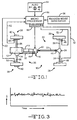
- Figure 3 is a graph illustrating a random noise signal produced by a generator according to the present invention.
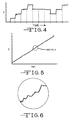
- Figure 4 is a graph illustrating the random noise signal according to the present invention superimposed upon an incremental (step-wise) clutch control signal of a clutch drive circuit
- Figure 5 is a graph illustrating the random noise signal superimposed upon an analog clutch control signal.
- Figure 6 is a greatly enlarged portion of the random noise signal signal generator and controller according to the present invention.
- the four-wheel vehicle drive train 10 includes a prime mover 12 which is coupled to and directly drives a transmission 14.
- the output of the transmission 14 directly drives a transfer case assembly 16 which provides motive power to a primary or rear drive driveline 20 comprising a primary or rear prop shaft 22, a primary or rear differential 24, a pair of live primary or rear axles 26 and a respective pair of primary or rear tire and wheel assemblies 28.
- the transfer case assembly 16 also selectively provides motive power to a secondary or front driveline 30 comprising a secondary or front prop shaft 32, a secondary or front differential 34, a pair of live secondary or front axles 36 and a respective pair of secondary or front tire and wheel assemblies 38.
- the front tire and wheel assemblies 38 may be directly coupled to a respective one of the front axles 36 or, if desired, a pair of manually or remotely activatable locking hubs 42 may be operably disposed between the front axles 36 and a respective one of the tire and wheel assemblies 38 to selectively connect same.
- both the primary driveline 20 and the secondary driveline 30 may include suitable and appropriately disposed universal joints 44 which function in conventional fashion to allow static and dynamic offsets and misalignments between the various shafts and components.
- a wheel speed sensor 48 Disposed in sensing relationship with each of the rear tire and wheel assemblies 28 is a wheel speed sensor 48.
- the wheel speed sensors 48 may be the same sensors utilized with, for example, an antilock brake system (ABS) or other vehicle control or traction enhancing system.
- ABS antilock brake system
- a single sensor, disposed to sense rotation of the primary or rear prop shaft 22 may be utilized. Signals from the sensors 48 are provided in lines 52 to a microprocessor 56.
- respective wheel speed sensors 58 disposed in sensing relationship with the front tire and wheel assemblies 38 are respective wheel speed sensors 58 which provide signals to the microprocessor 56 in lines 62.
- the sensors 58 may be a part of or shared with an antilock brake system or other traction control system.
- an operator selectable switch 64 may be utilized and is generally disposed within reach of the vehicle operator in the passenger compartment (not illustrated).
- the switch 64 may be adjusted to select various operating modes such as two-wheel high gear, automatic, i.e., on-demand or adaptive operation, four-wheel high gear or four-wheel low gear depending upon the particular vehicle and configuration of the transfer case assembly 16.
- One such system which provides torque delivery to the secondary driveline 30 in increments or decrements in response to a sensed wheel speed difference between the primary driveline 20 and the secondary driveline 30 is disclosed in United States Patent No. 5,407,024.
- a random noise (signal) generator' 66 Also providing a signal to the microprocessor 56 is a random noise (signal) generator' 66.
- the random noise generator 66 provides a signal which varies randomly over time and which is used, as described below, to enhance operational characteristics of the transfer case assembly 16 and four-wheel vehicle drive train 10.
- the output of the microprocessor 56 is a control signal which is delivered to a driver assembly 68 which increases the current flow of the output of the microprocessor 56 to a level sufficient to drive an electromagnetic clutch.
- a typical two-speed transfer case assembly 16 includes a multiple piece housing 70 having a plurality of planar sealing surfaces, openings for shafts and bearings and various recesses, shoulders, counterbores and the like which receive various components or assemblies of the transfer case assembly 16.
- An input shaft 72 includes female or internal splines 74 or other suitable coupling structures which drivingly engage and couple the output of the transmission 14 illustrated in Figure 1 to the input shaft 72.
- the input shaft 72 provides motive power to a planetary gear speed reduction assembly 76 which is controlled by a two or three position operator assembly 78 and shift fork and cam assembly 79 to achieve and provide a first, direct drive speed range (high gear), neutral and a second, reduced speed drive range (low gear).
- the output of the planetary gear speed reduction assembly 76 is provided to a primary output shaft 80 which is coupled to, and drives the primary driveline 20.
- the planetary gear assembly 76 and the operator assembly 78 are not present and the input shaft 72 or its equivalent directly drives the primary output shaft 80.
- a modulating clutch assembly 84 is operably disposed between the primary output shaft 80 and a chain drive sprocket 86 freely rotatably disposed about the primary output shaft 80.
- the chain drive sprocket 86 is engaged by a drive chain 88 which also engages a driven chain sprocket 90 which is secured to a secondary output shaft 92.
- the secondary output shaft 92 is coupled to and drives the secondary driveline 30.
- the modulating clutch 84 may be of any configuration utilizing an electromagnetic coil to cause motion of an associated device which results in compression of a friction clutch pack to a degree corresponding to the intensity of the drive signal to an electromagnetic coil.
- a clutch operator referred to as a ball ramp operator
- direct acting coils and bidirectional drive motors driving the clutch through, for example, gear reductions, sector plates and cams as well as other actuator configurations are all considered to be within the purview of the present invention.
- the modulating clutch 84 includes an electromagnetic coil 100 which is surrounded by a rotor 102 which is coupled to a first circular member 104.
- the first circular member 104 is disposed adjacent a second circular member 106.
- Adjacent, opposed circular members 104 and 106 include symmetrically configured ramped recesses which receive load transferring balls 108.
- energization of the coil 100 creates drag in the rotor 102 and associated first circular member 104 causing relative rotation between the first and second circular members 104 and 106 and driving the second circular member 106 toward a friction clutch pack 110 which is thereby compressed.
- Drive torque is thus transferred from the primary output shaft 80 through the compressed, interleaved plates or discs of the friction clutch pack 110 to a bell housing 112 which is coupled to and drives the chain drive sprocket 86. Reduction of the energization of the coil 100 reduces the just described torque transfer.
- the X-axis of Figure 3 represents time and the Y-axis represents voltage or intensity.
- the random noise signal illustrated represents the output of the random noise generator 66 which is provided to the microprocessor 56. Any one of numerous random noise generation techniques and components may be utilized. For example, a zener diode or an integrated circuit such as the LM 336 which can simulate the operation of a zener diode as well as numerous other random noise generators which are well known to those skilled in the art are wholly suitable in this application. Furthermore, while a pink noise signal is preferable, either white noise, pink noise or other random noise signal may be generated and used in the present invention.
- the output signal from the random noise generator 66 is combined with the drive signal generated by the microprocessor 56 and is provided to the driver circuitry 68 which increases the current and voltage of the logic signals utilized in the microprocessor 66 to levels which are suitable for operation of the electromagnetic coil 100.
- a digital, stepwise or incremental output control signal from the microprocessor 56 having a random noise signal from the random noise generator 66 superimposed thereupon is illustrated.
- the steps may be very small but are preferably on the order of 5% to 10% of maximum clutch engagement and are between 5 and 100 milliseconds duration and preferably between 10 to 50 milliseconds.
- the absolute value or proportion of the random noise signal from the random noise generator 66 to the voltage output of the microprocessor 56 and driver 68 is preferaby empiricly or experimentally determined through performance testing of the particular vehicle. This is so because the purpose of addition of the random noise signal is to match or compensate for other random variables, primarily within the clutch and the vehicle driveline, and thereby cancel or minimize them as described below. As Figures 4 and 5 illustrate, quantitatively the random noise signal is a small fraction or percentage of the magnitude of the overall control signal.
- a vehicle being operated at a constant speed with no internal, driver inputs or adjustments such as speed or steering variations and no external inputs such as road grade variations or winds affecting the operation of the vehicle. That is, it is operating at a steady state. Under this condition any, even small, variations in operation may be detected as an upset or perturbation to the steady state (and its accompanying sounds and perceptions) the driver and passengers have at least temporarily become accustomed to.
- the invention relates to modifying the engagement program or profile of a friction clutch, by the addition of random noise, not to engagement of a particular type of clutch.
- the present invention is wholly usable with any and all electrically engageable clutches in motor vehicle power trains which, for example, may utilize direct acting coils, linear motors, bidirectional motors driving clutches through gears, cams or sector plates, as the advantages of the present invention will be equally applicable and beneficial.
Landscapes
- Engineering & Computer Science (AREA)
- General Engineering & Computer Science (AREA)
- Physics & Mathematics (AREA)
- Mechanical Engineering (AREA)
- Electromagnetism (AREA)
- Fluid Mechanics (AREA)
- Hydraulic Clutches, Magnetic Clutches, Fluid Clutches, And Fluid Joints (AREA)
- Arrangement And Driving Of Transmission Devices (AREA)
Abstract
Description
Claims (20)
- A clutch system having improved engagement characteristics comprising, in combination:a microprocessor for receiving signals from vehicle sensors and providing a clutch engagement signal;a random noise generator providing a random noise signal;a friction clutch pack having an input and an output; andan electromagnetic operator for receiving said clutch engagement and said random noise signals and engaging said friction clutch pack.
- The clutch system of Claim 1 further including a driver assembly for amplifying said clutch engagement and said random noise signals.
- The clutch system of Claim 1 wherein said friction clutch pack is a modulating clutch.
- The clutch system of Claim 1 wherein said microprocessor provides an incremental clutch engagement signal.
- The clutch system of Claim 1 wherein said microprocessor provides an analog clutch engagement signal.
- The clutch system of Claim 1 further including a transfer case having a primary output and a second output and wherein said input and said output of said friction clutch pack are coupled to said primary output and said secondary output of said transfer case, respectively.
- The clutch system of Claim 1 wherein said random noise signal is selected from the group consisting of white noise and pink noise.
- A clutch system for a motor vehicle having improved engagement characteristics comprising, in combination:microprocessor means for receiving signals from at least one vehicle sensor and providing a clutch engagement signal;means for generating a random noise signal;clutch means having an input and an output; andelectromagnetic means for receiving said signals from said microprocessor and said random noise generating means and engaging and disengaging said clutch means.
- The clutch system of Claim 8 further including a driver assembly for amplifying said clutch engagement and said random noise signals.
- The clutch system of Claim 8 wherein said clutch means is a modulating friction pack clutch.
- The clutch system of Claim 8 wherein said microprocessor means provides an incremental clutch engagement signal.
- The clutch system of Claim 8 wherein said microprocessor means provides an analog clutch engagement signal.
- The clutch system of Claim 8 wherein said random noise signal is selected from the group consisting of white noise and pink noise.
- The clutch system of Claim 8 further including a transfer case having a primary output and a second output and wherein said input and said output of said friction clutch pack are coupled to said primary output and said secondary output of said transfer case, respectively.
- A method of providing improved engagement of an electromagnetically operated clutch comprising the steps of:providing a clutch engagement signal;providing a random noise signal;combining said clutch engagement signal and said random noise signal; andproviding said clutch engagement and random noise signals to an electromagnetic operator of a friction clutch.
- The method of Claim 15 further including the step of providing a vehicle sensor output signal.
- The method of Claim 15 further including the step of amplifying said clutch engagement signal and said random noise signal.
- The method of Claim 15 wherein said clutch engagement signal is an incremental signal.
- The method of Claim 15 wherein said clutch engagement signal is an analog signal.
- The method of Claim 15 wherein said random noise signal is selected from the group consisting of white noise and pink noise.
Applications Claiming Priority (2)
| Application Number | Priority Date | Filing Date | Title |
|---|---|---|---|
| US303599 | 2002-11-25 | ||
| US10/303,599 US6725992B1 (en) | 2002-11-25 | 2002-11-25 | Electromagnetic clutch control providing enhanced engagement |
Publications (2)
| Publication Number | Publication Date |
|---|---|
| EP1422102A2 true EP1422102A2 (en) | 2004-05-26 |
| EP1422102A3 EP1422102A3 (en) | 2005-08-24 |
Family
ID=32107690
Family Applications (1)
| Application Number | Title | Priority Date | Filing Date |
|---|---|---|---|
| EP03017510A Withdrawn EP1422102A3 (en) | 2002-11-25 | 2003-08-05 | Electromagnetic clutch control providing enhanced engagement |
Country Status (4)
| Country | Link |
|---|---|
| US (1) | US6725992B1 (en) |
| EP (1) | EP1422102A3 (en) |
| JP (1) | JP2004176914A (en) |
| KR (1) | KR20040045281A (en) |
Families Citing this family (3)
| Publication number | Priority date | Publication date | Assignee | Title |
|---|---|---|---|---|
| WO2007025162A2 (en) * | 2005-08-26 | 2007-03-01 | Borgwarner Inc. | Fast turn-off and fast turn-on of an inductive load and usage in vehicle application |
| US20110213532A1 (en) * | 2010-03-01 | 2011-09-01 | Blair Ricky E | Method and system for controlling a two-speed transfer case |
| DE102014016451B3 (en) * | 2014-11-06 | 2016-03-24 | Audi Ag | Method for operating a multi-axle drive train for a motor vehicle and corresponding multi-axis drive train |
Family Cites Families (6)
| Publication number | Priority date | Publication date | Assignee | Title |
|---|---|---|---|---|
| JPH04351500A (en) | 1991-05-29 | 1992-12-07 | Mitsubishi Electric Corp | Electromagnetic clutch controller for vehicle |
| US5407024A (en) * | 1992-06-24 | 1995-04-18 | Borg-Warner Automotive, Inc. | On demand vehicle drive system |
| DE19515842A1 (en) * | 1995-04-29 | 1996-10-31 | Teves Gmbh Alfred | Setpoint generator |
| JP3409537B2 (en) * | 1995-10-19 | 2003-05-26 | 日産自動車株式会社 | Vehicle four-wheel drive control device |
| US5704444A (en) | 1995-12-11 | 1998-01-06 | Borg-Warner Automotive, Inc. | Adaptive vehicle drive system for extreme operating conditioning |
| US5771477A (en) * | 1996-05-10 | 1998-06-23 | Borg-Warner Automotive, Inc. | Method and apparatus for synchronizing low to high transfer case shifts |
-
2002
- 2002-11-25 US US10/303,599 patent/US6725992B1/en not_active Expired - Fee Related
-
2003
- 2003-08-05 EP EP03017510A patent/EP1422102A3/en not_active Withdrawn
- 2003-09-02 KR KR1020030061078A patent/KR20040045281A/en not_active Withdrawn
- 2003-10-08 JP JP2003349406A patent/JP2004176914A/en active Pending
Also Published As
| Publication number | Publication date |
|---|---|
| KR20040045281A (en) | 2004-06-01 |
| JP2004176914A (en) | 2004-06-24 |
| EP1422102A3 (en) | 2005-08-24 |
| US6725992B1 (en) | 2004-04-27 |
Similar Documents
| Publication | Publication Date | Title |
|---|---|---|
| US7497286B2 (en) | Auxiliary electric drive assembly | |
| US5655986A (en) | Full-time transfer case with synchronized single planetary gear reduction unit | |
| US5373912A (en) | Control system for restrictively controlling electromagnetically controlled differential | |
| US7601089B2 (en) | Power transfer unit with torque vectoring drive mechanism | |
| EP1118493A2 (en) | Method and apparatus for providing range shift synchronization in a transfer case | |
| WO2005116489A2 (en) | Torque distributing differential assembly | |
| WO2006060139A2 (en) | Torque vectoring device having an electric motor/brake actuator and friction clutch | |
| EP1841614B1 (en) | Torque vectoring axle assembly | |
| US6935476B2 (en) | Clutch having a multiple pole electromagnetic actuator for transfer cases and the like | |
| US6848550B2 (en) | Torque transfer system with two stage ball ramp/clutch actuation | |
| CN114248623A (en) | Inter-axle differential and method of operating the same | |
| US6725992B1 (en) | Electromagnetic clutch control providing enhanced engagement | |
| US7425183B2 (en) | Transfer case for regenerative hydraulic drive | |
| US20040180747A1 (en) | Transfer case having input shaft electromagnetic brake | |
| CA2232766A1 (en) | Four-wheel drive transmission | |
| JP3627288B2 (en) | Four-wheel drive device | |
| JPH08324288A (en) | Four-wheel drive | |
| JPH08324274A (en) | Four-wheel drive | |
| JP2007223370A (en) | Control device for four-wheel drive vehicle |
Legal Events
| Date | Code | Title | Description |
|---|---|---|---|
| PUAI | Public reference made under article 153(3) epc to a published international application that has entered the european phase |
Free format text: ORIGINAL CODE: 0009012 |
|
| AK | Designated contracting states |
Kind code of ref document: A2 Designated state(s): AT BE BG CH CY CZ DE DK EE ES FI FR GB GR HU IE IT LI LU MC NL PT RO SE SI SK TR |
|
| AX | Request for extension of the european patent |
Extension state: AL LT LV MK |
|
| RIN1 | Information on inventor provided before grant (corrected) |
Inventor name: TUBBS, FREDRIC H. Inventor name: RAY, DAVID E. |
|
| RAP1 | Party data changed (applicant data changed or rights of an application transferred) |
Owner name: BORGWARNER INC. |
|
| PUAL | Search report despatched |
Free format text: ORIGINAL CODE: 0009013 |
|
| AK | Designated contracting states |
Kind code of ref document: A3 Designated state(s): AT BE BG CH CY CZ DE DK EE ES FI FR GB GR HU IE IT LI LU MC NL PT RO SE SI SK TR |
|
| AX | Request for extension of the european patent |
Extension state: AL LT LV MK |
|
| AKX | Designation fees paid |
Designated state(s): DE GB |
|
| STAA | Information on the status of an ep patent application or granted ep patent |
Free format text: STATUS: THE APPLICATION IS DEEMED TO BE WITHDRAWN |
|
| 18D | Application deemed to be withdrawn |
Effective date: 20060301 |