EP1422069A1 - A printing apparatus having a media defect detection system - Google Patents
A printing apparatus having a media defect detection system Download PDFInfo
- Publication number
- EP1422069A1 EP1422069A1 EP03078534A EP03078534A EP1422069A1 EP 1422069 A1 EP1422069 A1 EP 1422069A1 EP 03078534 A EP03078534 A EP 03078534A EP 03078534 A EP03078534 A EP 03078534A EP 1422069 A1 EP1422069 A1 EP 1422069A1
- Authority
- EP
- European Patent Office
- Prior art keywords
- media
- defect
- defects
- printing
- images
- Prior art date
- Legal status (The legal status is an assumption and is not a legal conclusion. Google has not performed a legal analysis and makes no representation as to the accuracy of the status listed.)
- Withdrawn
Links
- 230000007547 defect Effects 0.000 title claims abstract description 179
- 238000001514 detection method Methods 0.000 title abstract description 18
- 239000003550 marker Substances 0.000 claims abstract description 27
- 238000000034 method Methods 0.000 claims abstract description 19
- 230000002950 deficient Effects 0.000 abstract description 4
- 238000004519 manufacturing process Methods 0.000 description 8
- 238000007689 inspection Methods 0.000 description 6
- 239000002699 waste material Substances 0.000 description 4
- 230000000694 effects Effects 0.000 description 1
- 230000008030 elimination Effects 0.000 description 1
- 238000003379 elimination reaction Methods 0.000 description 1
- 239000002245 particle Substances 0.000 description 1
- 230000035945 sensitivity Effects 0.000 description 1
- 230000011664 signaling Effects 0.000 description 1
- 230000003746 surface roughness Effects 0.000 description 1
- 238000004804 winding Methods 0.000 description 1
Images



Classifications
-
- B—PERFORMING OPERATIONS; TRANSPORTING
- B41—PRINTING; LINING MACHINES; TYPEWRITERS; STAMPS
- B41J—TYPEWRITERS; SELECTIVE PRINTING MECHANISMS, i.e. MECHANISMS PRINTING OTHERWISE THAN FROM A FORME; CORRECTION OF TYPOGRAPHICAL ERRORS
- B41J11/00—Devices or arrangements of selective printing mechanisms, e.g. ink-jet printers or thermal printers, for supporting or handling copy material in sheet or web form
- B41J11/008—Controlling printhead for accurately positioning print image on printing material, e.g. with the intention to control the width of margins
-
- B—PERFORMING OPERATIONS; TRANSPORTING
- B41—PRINTING; LINING MACHINES; TYPEWRITERS; STAMPS
- B41J—TYPEWRITERS; SELECTIVE PRINTING MECHANISMS, i.e. MECHANISMS PRINTING OTHERWISE THAN FROM A FORME; CORRECTION OF TYPOGRAPHICAL ERRORS
- B41J11/00—Devices or arrangements of selective printing mechanisms, e.g. ink-jet printers or thermal printers, for supporting or handling copy material in sheet or web form
- B41J11/009—Detecting type of paper, e.g. by automatic reading of a code that is printed on a paper package or on a paper roll or by sensing the grade of translucency of the paper
Definitions
- the present invention relates to a printing apparatus and a method of printing, wherein the printing apparatus includes a media defect detection system for detecting defects on media and controlling subsequent printing on the media.
- Manufactured media can be inspected on a master roll before it is slit into finished rolls at a manufacturing site and can be manually inspected at a photofinishing or printing site.
- media such as color paper rolls with defects that meet a certain size criteria as detected at the manufacturing site are discarded and not passed on to the photofinisher.
- Large-scale photofinishers can utilize 4 inch by 1800-foot rolls and can be quite inflexible on variations in roll length. The effect of this combination means that when a single defect falls within a customer roll, the entire customer roll may be discarded as waste since the defect in the media will show up on a completed print, resulting in a defective image. All other prints of the roll may be acceptable.
- some media defects can be of a characteristic that will not be noticeable in a finished print, potentially making all prints of that roll acceptable. Therefore, discarding an entire customer roll due to certain defects leads to waste of media.
- the defects are not detected at the manufacturing site, they will have to be detected at a photofinishing site.
- a manual inspection occurs at the photofinishing site. This inspection is time consuming, inefficient, and depends on the skill of an operator.
- the system and apparatus of the present invention reduces unnecessary waste by precisely locating media defects and either not printing the media frames associated with those defects or identifying the prints made on those frames for rejection and making replacement prints on clean media. This prevents an entire customer roll from being discarded when a single defect is found in that roll during manufacturing. Thereafter, printing is controlled by preventing the defect from getting onto a print or by remaking the defective print.
- the present invention provides for a printer or printing apparatus, which is interfaced with a defect detection system capable of precisely identifying a defect and the location of the defect on the media.
- a defect detection system capable of precisely identifying a defect and the location of the defect on the media.
- manufactured media can be forwarded to a photofinishing site without discarding media with defects thereon.
- the printer of the present invention is capable of scanning the media to detect defects of a particular characteristic and providing for a physical mark on the media in close proximity of the noted defect or electronically reporting the precise location of the defect. The printer is thereby instructed to either skip over the defect frames or reprint the image frames upon which the defects will fall.
- the printer is interfaced with the defect scanning system and a defect marker or signaling device.
- the scanning system can be off-line on a separate conveying system (i.e., a rewinder), and mark the position of the defect, so that the printer can detect it.
- a preferred method of marking the location of the defect on the media involves marking it by way of a punch to form a hole in the center of the media just ahead of where the defect is located. With this approach, the printer will skip the hole and defect frames similarly to the way it skips splice frames marked with a hole. This center hole is not to be confused with the punched holes that can be at other locations on the media.
- the present invention therefore provides for a printing apparatus which comprises a defect scanning section for scanning unexposed media in a media path in the printing apparatus to detect defects of a predetermined characteristic on the media; a defect marker located downstream of the defect scanning section with respect to a direction of travel of the media in the printing apparatus, with the defect marker receiving a signal from the defect scanning section indicative of a defect in the media and placing a physical mark on the media near the detected defect, such that the physical mark is associated with an image frame carrying the defect; and a printing section for printing images on the media, with the printing section being able to scan the media for the physical marks and skip the frames of the media which include the physical marks and their associated defects, such that the printing section prints images on only those frames which have no defects or physical marks.
- the present invention further provides for a printing apparatus that comprises a defect scanning section for scanning unexposed media in a media path of the printing apparatus, to detect defects of a predetermined characteristic on the media; a defect marker located downstream of the defect scanning section with respect to a direction of travel of the media in the printing section, with the defect marker receiving a signal from the defect scanning section indicative of a defect in the media and placing a physical mark on the media near the detected defect, such that the physical mark is associated with an image frame carrying the defect; and a printing section for printing images on the media, with the printing section being adapted to scan the media for the physical marks and print images on the image frames, wherein images printed in frames having the physical marks and their associated defects are reprinted on defect-free media and the defective prints are discarded.
- a printing apparatus that comprises a defect scanning section for scanning unexposed media in a media path of the printing apparatus, to detect defects of a predetermined characteristic on the media; a defect marker located downstream of the defect scanning section with respect to a direction of travel of the media in
- the present invention further relates to a method of printing images on media which comprises the steps of scanning media to detect a precise location of defects of a predetermined characteristic on the media; transmitting information with respect to the detected defects electronically to a printing section of a printer; and using the information to control subsequent printing of images by the printer on the media by skipping frames with the defects and printing images on defect-free media.
- the present invention further relates to a method of printing images on media which comprises the steps of scanning media to detect a precise location of defects of a predetermined characteristic on the media; transmitting information with respect to the detected defects electronically to a printing section of a printer; and using the information to reprint those images which are printed on frames having defects, while tracking and discarding the prints with defects thereon.
- Printer 2 includes a media path schematically illustrated by reference numeral 14, which extends through printer 2.
- Media path 14 is adapted to convey media through the different sections of printer 2.
- Printer 2 can be a known printer, which exposes and prints on photographic paper or media.
- printer 2 includes an entrance 30 for receiving unexposed photographic paper or media 4.
- Photographic paper or media 4 is conveyed via media path 14 to a defect detector or defect detection section 6 which is interfaced with printer 2.
- Defect detection section 6 can be a known scanner, or camera, which scans the entire web of unexposed media 4.
- defect detection section 6 can comprise a video camera equipped with a lens, which images an entire frame of a web of photographic media to detect defects therein.
- defect detection section 6 can include an IR light emitter, which applies IR light to the photographic media in a manner that does not alter the media's sensitivity to visible light.
- the scanner or camera scans all of the frames of unexposed media 4 looking for defects of a specific characteristic. That is, there are certain defects allowed to pass through because they will not be noticeable in the final print. Examples of these are: slight surface roughness variations, extremely small point defects without a strong color contrast, and fine scratches invisible to the human eye. Multiple and repeating defects can be rejected beforehand at the manufacturing site, so that only an occasional defect must be handled by the printing system. A goal of inspection at the printer location is to eliminate random single media defects that will show up in the final print.
- Defect detection section 6 can utilize an algorithm method in which the edges of the web of photographic media are detected and a digital filter is applied to enhance any defects. Thereafter, a binary image can be created to determine any bright spot defects and/or particle analysis is performed to identify the size and the position of the defects. As noted above, certain types of defects will not appear in the final print and therefore, no defect marker is needed. Those defects that are of a specific characteristic, outside of an allowable range or above an allowable limit are considered an objectional defect and accordingly, the frame of the media which includes that defect is appropriately marked.
- a defect marker 8 is enabled.
- Defect marker 8 can be a known hole puncher (see Fig. 1B) which will accordingly make a physical mark on the media in the vicinity of the defect.
- An example of the defect and marker are shown in Fig 2, in which media 4 contains a punched hole 120 that is shown in the vicinity of defect 110.
- reference numeral 100 represents an unwind or supply roll
- reference numeral 130 represents a winding or take-up roll
- Defect detection section 6 is adapted to detect defect 110 on media 4 and supply a signal to defect marker 8 to provide for punched hole 120 in the vicinity of defect 110.
- defect marker 8 marks the frame of the media that includes the defect with a physical mark such as a hole
- media 4 continues along media path 14 to a printing or exposure section 10 within printer 2.
- Printing or exposure section 10 includes a sensor (see, for example, reference numeral 230 in Fig. 1B) that would scan the media prior to exposure to check for any defect markers (such as punched hole 120).
- printing section 10 skips those frames that include the defects and defect markers such as physical holes, are skipped by printing section 10 and more specifically, no images are printed on those frames which include a defect or a defect marker.
- the defect marker would appear at random positions along the media since the markers would be at only those frames that include a defect.
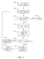
- the inspection process for a given roll of media 4 is described in the flowchart of Fig 3.
- the media 4 is first fed into printer 2 (step 300) and positioned prior to the first image frame.
- the media is then advanced to the next image frame (step 310).
- the media is then tested to see if the end of the roll of media has been reached (360). If the end of media has been reached, the process stops (step 370). If the end of media has not been reached, the frame is scanned (step 320) by defect detection station 6.
- the scanned frame is then analyzed for defects (step 330). If an objectionable defect is detected (step 340), defect marker 8 is enabled (step 341). As described, defect marker 8 is adapted to place a physical mark on the media (step 342) in the vicinity of the defect.
- the sensor in the printing section 10 can detect the physical mark and the printing section can skip the defect area by advancing the media to the next frame (step 310). If no defect is detected (step 340), the media frame is used normally (step 350). The process is then repeated by advancing to the next frame (step 310).
- printing section 10 would print the images on all the frames of the media. Thereafter, printer 2 can include a detector 12 (Fig. 1A) which will detect those printed image frames that include the defect marker, in addition to machine logic that includes defect frames with each marker frame for reprinting. At that point, those images would be sent back via path 18 for reprinting at printing section 10 (Fig. 1A).
- a detector 12 FIG. 1A
- the scanning system can be off-line on a separate conveying system, as shown in Fig 4.
- the scanning and defect marker will mark the position of the defect as previously described.
- media 4 is unrolled from unwind roll 100, it is scanned by defect detection station 6.
- defect marker 8 places a mark on the media in the vicinity of the defect position.
- the media is then wound up onto windup roll 130 and the process repeated until the end of roll is reached. Thereafter, the roll of media is fed into the printer and the printing section enabled to skip those frames that include defect markers and their associated defects.
- the images can be printed on each of the frames and thereafter, the media is scanned to identify those images which have been printed on the frames with defect markers and defects. Those images are then reprinted as noted above.
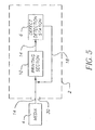
- FIG. 5 Another embodiment of the present invention is depicted in Fig 5.
- media 4 is fed into printer 2 through entrance 30 via media path 14, and the media is then exposed by printing section 10. Since the exposed media has not yet been developed by a photoprocessor, the printed image is not visible and the media can be inspected by defect detection station 6. When a defect is found, the affected image or images can be sent back via path 18 for reprinting at printing section 10.
- defect detection section 6 is adapted to scan media to detect a precise location of defects. Once detected, information with respect to the detected defects can be electronically transmitted to a printing section of a printer to control subsequent printing of images by (a) skipping frames with the defects and printing images on defect-free frames, or (b) using the information to reprint those images which are printed on frames having defects, while tracking and discarding prints with defects.
- defects within allowable limits. For example, a small, low-contrast defect may be acceptable while a large, high-contrast defect would be unacceptable. Such defects can be differentiated by characteristics such as size, shape, or contrast.
- printer 2 of the present invention, the media is automatically inspected as it is consumed by the printer by the combination of the scanner and defect marker, and printing is subsequently controlled in consideration of the frames having defect markers thereon. For the elimination of the media inspection at the manufacturing site to be practical, however, a low frequency of defect occurrences is required.
- the media is preferably non-magnetic media, and accordingly, the use of a physical mark, i.e. a punch hole, is preferred with respect to forming the mark and detecting the mark within the printer.
- the mark can be a hole in the center of the media, a notch at the edge of the media, or a colored mark applied with an inkjet or laser at the defect marking station. It is noted that the defect marks would be randomly occurring marks of predetermined characteristics.
Landscapes
- Investigating Materials By The Use Of Optical Means Adapted For Particular Applications (AREA)
- Accessory Devices And Overall Control Thereof (AREA)
- Inking, Control Or Cleaning Of Printing Machines (AREA)
Abstract
The present invention relates to a photographic printer (2) and a
method of printing in which the printer is interfaced with a defect detection or
scanning system that is adapted to inspect photographic paper for defects as it is
consumed by the printer. In the system and method of the present invention, when
a defect is detected, the printer is enabled to either skip over the defect area or to
reprint the affected image. With respect to the defect, when detected, the present
invention provides either for the utilization of a defect marker (8), such as a hole
punch, which provides a physical mark on the paper in close vicinity of the defect
or an electronic device capable of transmitting the precise location of the defect to
the printing section. The hole or electronic signal is recognized by the printer, to
enable it to either skip the defective frames or reprint the images.
Description
- The present invention relates to a printing apparatus and a method of printing, wherein the printing apparatus includes a media defect detection system for detecting defects on media and controlling subsequent printing on the media.
- During the manufacture of media such as photographic paper, defects can occur on the media. Manufactured media can be inspected on a master roll before it is slit into finished rolls at a manufacturing site and can be manually inspected at a photofinishing or printing site.
- Typically, media such as color paper rolls with defects that meet a certain size criteria as detected at the manufacturing site are discarded and not passed on to the photofinisher. Large-scale photofinishers can utilize 4 inch by 1800-foot rolls and can be quite inflexible on variations in roll length. The effect of this combination means that when a single defect falls within a customer roll, the entire customer roll may be discarded as waste since the defect in the media will show up on a completed print, resulting in a defective image. All other prints of the roll may be acceptable. In addition, some media defects can be of a characteristic that will not be noticeable in a finished print, potentially making all prints of that roll acceptable. Therefore, discarding an entire customer roll due to certain defects leads to waste of media.
- If the defects are not detected at the manufacturing site, they will have to be detected at a photofinishing site. Typically, a manual inspection occurs at the photofinishing site. This inspection is time consuming, inefficient, and depends on the skill of an operator.
- The system and apparatus of the present invention reduces unnecessary waste by precisely locating media defects and either not printing the media frames associated with those defects or identifying the prints made on those frames for rejection and making replacement prints on clean media. This prevents an entire customer roll from being discarded when a single defect is found in that roll during manufacturing. Thereafter, printing is controlled by preventing the defect from getting onto a print or by remaking the defective print.
- The present invention provides for a printer or printing apparatus, which is interfaced with a defect detection system capable of precisely identifying a defect and the location of the defect on the media. With the printer of the present invention, manufactured media can be forwarded to a photofinishing site without discarding media with defects thereon. The printer of the present invention is capable of scanning the media to detect defects of a particular characteristic and providing for a physical mark on the media in close proximity of the noted defect or electronically reporting the precise location of the defect. The printer is thereby instructed to either skip over the defect frames or reprint the image frames upon which the defects will fall. In the embodiment of the invention as described above, the printer is interfaced with the defect scanning system and a defect marker or signaling device. In a further variation of the present invention, the scanning system can be off-line on a separate conveying system (i.e., a rewinder), and mark the position of the defect, so that the printer can detect it.
- A preferred method of marking the location of the defect on the media involves marking it by way of a punch to form a hole in the center of the media just ahead of where the defect is located. With this approach, the printer will skip the hole and defect frames similarly to the way it skips splice frames marked with a hole. This center hole is not to be confused with the punched holes that can be at other locations on the media.
- The present invention therefore provides for a printing apparatus which comprises a defect scanning section for scanning unexposed media in a media path in the printing apparatus to detect defects of a predetermined characteristic on the media; a defect marker located downstream of the defect scanning section with respect to a direction of travel of the media in the printing apparatus, with the defect marker receiving a signal from the defect scanning section indicative of a defect in the media and placing a physical mark on the media near the detected defect, such that the physical mark is associated with an image frame carrying the defect; and a printing section for printing images on the media, with the printing section being able to scan the media for the physical marks and skip the frames of the media which include the physical marks and their associated defects, such that the printing section prints images on only those frames which have no defects or physical marks.
- The present invention further provides for a printing apparatus that comprises a defect scanning section for scanning unexposed media in a media path of the printing apparatus, to detect defects of a predetermined characteristic on the media; a defect marker located downstream of the defect scanning section with respect to a direction of travel of the media in the printing section, with the defect marker receiving a signal from the defect scanning section indicative of a defect in the media and placing a physical mark on the media near the detected defect, such that the physical mark is associated with an image frame carrying the defect; and a printing section for printing images on the media, with the printing section being adapted to scan the media for the physical marks and print images on the image frames, wherein images printed in frames having the physical marks and their associated defects are reprinted on defect-free media and the defective prints are discarded.
- The present invention further relates to a method of printing images on media which comprises the steps of scanning media to detect a precise location of defects of a predetermined characteristic on the media; transmitting information with respect to the detected defects electronically to a printing section of a printer; and using the information to control subsequent printing of images by the printer on the media by skipping frames with the defects and printing images on defect-free media.
- The present invention further relates to a method of printing images on media which comprises the steps of scanning media to detect a precise location of defects of a predetermined characteristic on the media; transmitting information with respect to the detected defects electronically to a printing section of a printer; and using the information to reprint those images which are printed on frames having defects, while tracking and discarding the prints with defects thereon.
- Figure 1A schematically illustrates a printer or printing apparatus in accordance with the present invention;
- Figure 1B is a further illustration of the printer or printing apparatus of the present invention;
- Figure 2 is a perspective view showing an example of a defect marker on the media in the vicinity of the defect;
- Figure 3 is a flowchart describing a defect handling process used by the printer or printing apparatus in accordance with the present invention;
- Figure 4 is a perspective view illustrating an alternative embodiment in which the defect detection and marking system is separate from the printer or printing apparatus; and
- Figure 5 schematically illustrates an alternative embodiment of the printer or printing apparatus in which exposed media is inspected for defects.
-
- Referring now to Figs. 1A and 1B, a printer or
printing apparatus 2 in accordance with the present invention is schematically shown.Printer 2 includes a media path schematically illustrated byreference numeral 14, which extends throughprinter 2.Media path 14 is adapted to convey media through the different sections ofprinter 2.Printer 2 can be a known printer, which exposes and prints on photographic paper or media. - As shown in Fig. 1A,
printer 2 includes anentrance 30 for receiving unexposed photographic paper ormedia 4. Photographic paper ormedia 4 is conveyed viamedia path 14 to a defect detector ordefect detection section 6 which is interfaced withprinter 2.Defect detection section 6 can be a known scanner, or camera, which scans the entire web ofunexposed media 4. For example, as shown in Fig. 1B,defect detection section 6 can comprise a video camera equipped with a lens, which images an entire frame of a web of photographic media to detect defects therein. As a further option,defect detection section 6 can include an IR light emitter, which applies IR light to the photographic media in a manner that does not alter the media's sensitivity to visible light. - With respect to
defect detection section 6, the scanner or camera scans all of the frames ofunexposed media 4 looking for defects of a specific characteristic. That is, there are certain defects allowed to pass through because they will not be noticeable in the final print. Examples of these are: slight surface roughness variations, extremely small point defects without a strong color contrast, and fine scratches invisible to the human eye. Multiple and repeating defects can be rejected beforehand at the manufacturing site, so that only an occasional defect must be handled by the printing system. A goal of inspection at the printer location is to eliminate random single media defects that will show up in the final print. -
Defect detection section 6 can utilize an algorithm method in which the edges of the web of photographic media are detected and a digital filter is applied to enhance any defects. Thereafter, a binary image can be created to determine any bright spot defects and/or particle analysis is performed to identify the size and the position of the defects. As noted above, certain types of defects will not appear in the final print and therefore, no defect marker is needed. Those defects that are of a specific characteristic, outside of an allowable range or above an allowable limit are considered an objectional defect and accordingly, the frame of the media which includes that defect is appropriately marked. - As shown in Fig. 1A, after the web of
media 4 is scanned atdefect detection section 6 and any defects above a particular limit are detected, adefect marker 8 is enabled.Defect marker 8 can be a known hole puncher (see Fig. 1B) which will accordingly make a physical mark on the media in the vicinity of the defect. An example of the defect and marker are shown in Fig 2, in whichmedia 4 contains apunched hole 120 that is shown in the vicinity ofdefect 110. - In the example of Fig. 2,
reference numeral 100 represents an unwind or supply roll, whilereference numeral 130 represents a winding or take-up roll.Defect detection section 6 is adapted to detectdefect 110 onmedia 4 and supply a signal to defectmarker 8 to provide for punchedhole 120 in the vicinity ofdefect 110. - After
defect marker 8 marks the frame of the media that includes the defect with a physical mark such as a hole,media 4 continues alongmedia path 14 to a printing orexposure section 10 withinprinter 2. Printing orexposure section 10 includes a sensor (see, for example,reference numeral 230 in Fig. 1B) that would scan the media prior to exposure to check for any defect markers (such as punched hole 120). In one embodiment of the present invention, printingsection 10 skips those frames that include the defects and defect markers such as physical holes, are skipped by printingsection 10 and more specifically, no images are printed on those frames which include a defect or a defect marker. In the arrangement of the present invention, the defect marker would appear at random positions along the media since the markers would be at only those frames that include a defect. - The inspection process for a given roll of
media 4 is described in the flowchart of Fig 3. Themedia 4 is first fed into printer 2 (step 300) and positioned prior to the first image frame. The media is then advanced to the next image frame (step 310). The media is then tested to see if the end of the roll of media has been reached (360). If the end of media has been reached, the process stops (step 370). If the end of media has not been reached, the frame is scanned (step 320) bydefect detection station 6. The scanned frame is then analyzed for defects (step 330). If an objectionable defect is detected (step 340),defect marker 8 is enabled (step 341). As described,defect marker 8 is adapted to place a physical mark on the media (step 342) in the vicinity of the defect. Thereafter, the sensor in theprinting section 10 can detect the physical mark and the printing section can skip the defect area by advancing the media to the next frame (step 310). If no defect is detected (step 340), the media frame is used normally (step 350). The process is then repeated by advancing to the next frame (step 310). - In a further embodiment of the present invention, printing
section 10 would print the images on all the frames of the media. Thereafter,printer 2 can include a detector 12 (Fig. 1A) which will detect those printed image frames that include the defect marker, in addition to machine logic that includes defect frames with each marker frame for reprinting. At that point, those images would be sent back viapath 18 for reprinting at printing section 10 (Fig. 1A). - In a still further feature of the present invention, rather than having the scanner and defect marker interface with
printer 2 as shown in Fig. 1A, the scanning system can be off-line on a separate conveying system, as shown in Fig 4. In the alternative embodiment, the scanning and defect marker will mark the position of the defect as previously described. Asmedia 4 is unrolled from unwindroll 100, it is scanned bydefect detection station 6. Upon detection of a defect,defect marker 8 places a mark on the media in the vicinity of the defect position. The media is then wound up ontowindup roll 130 and the process repeated until the end of roll is reached. Thereafter, the roll of media is fed into the printer and the printing section enabled to skip those frames that include defect markers and their associated defects. As a further option, the images can be printed on each of the frames and thereafter, the media is scanned to identify those images which have been printed on the frames with defect markers and defects. Those images are then reprinted as noted above. - Another embodiment of the present invention is depicted in Fig 5. In this embodiment,
media 4 is fed intoprinter 2 throughentrance 30 viamedia path 14, and the media is then exposed by printingsection 10. Since the exposed media has not yet been developed by a photoprocessor, the printed image is not visible and the media can be inspected bydefect detection station 6. When a defect is found, the affected image or images can be sent back viapath 18 for reprinting atprinting section 10. - Therefore, in an embodiment of the system and method of the present invention,
defect detection section 6 is adapted to scan media to detect a precise location of defects. Once detected, information with respect to the detected defects can be electronically transmitted to a printing section of a printer to control subsequent printing of images by (a) skipping frames with the defects and printing images on defect-free frames, or (b) using the information to reprint those images which are printed on frames having defects, while tracking and discarding prints with defects. - With the system and method of the present invention as described above, it is possible to print on media which includes defects within allowable limits. For example, a small, low-contrast defect may be acceptable while a large, high-contrast defect would be unacceptable. Such defects can be differentiated by characteristics such as size, shape, or contrast.
- The ability to utilize media rolls containing a small number of defects helps to reduce media waste. Further, it is possible to eliminate a media inspection step or process within the media-manufacturing warehouse by having
printer 2 as shown above. Withprinter 2 of the present invention, the media is automatically inspected as it is consumed by the printer by the combination of the scanner and defect marker, and printing is subsequently controlled in consideration of the frames having defect markers thereon. For the elimination of the media inspection at the manufacturing site to be practical, however, a low frequency of defect occurrences is required. - With respect to the media of the present invention, the media is preferably non-magnetic media, and accordingly, the use of a physical mark, i.e. a punch hole, is preferred with respect to forming the mark and detecting the mark within the printer. The mark can be a hole in the center of the media, a notch at the edge of the media, or a colored mark applied with an inkjet or laser at the defect marking station. It is noted that the defect marks would be randomly occurring marks of predetermined characteristics.
Claims (6)
- A printing apparatus (2) comprising:a defect scanning section for scanning unexposed media (4) in a media path (14) in said printing apparatus to detect defects of a predetermined characteristic on said media;a defect marker (8) located downstream of said scanning section with respect to a direction of travel of said media in said printing apparatus, said defect marker receiving a signal from said defect scanning section indicative of a defect in said media and placing a physical mark on said media near the detected defect, such that said physical mark is associated with an image frame which includes said defect; anda printing section (10) for printing images on said media, said printing section being adapted to examine the media for said physical marks and skip the frames of the media which include the physical marks and their associated defects, such that said printing section prints images on only those frames which have no physical marks or associated defects on them.
- A printing apparatus according to claim 1, wherein said physical mark is a hole punched in said media.
- A printing apparatus comprising:a defect scanning section (6) for scanning unexposed media (4) in a media path (14) of said printing apparatus, to detect defects of a predetermined characteristic on said media;a defect marker (8) located downstream of said scanning section with respect to a direction of travel of said media in said printing apparatus, said defect marker receiving a signal from said defect scanning section indicative of a defect in said media and placing a physical mark on said media near the detected defect, such that said physical mark is associated with an image frame which includes said defect; and
a printing section (10) for printing images on said media, said printing section being adapted to examine the media for said physical marks and print images on said image frames, wherein images printed in frames having said physical marks and their associated defects are reprinted on defect-free media and prints with defects are discarded. - A printing apparatus according to claim 3, wherein said physical mark is a hole punched in said media.
- A method of printing images on media, the method comprising the steps of:scanning media to detect a location of defects of a predetermined characteristic on the media; andtransmitting information with respect to the detected defects electronically to a printing section of a printer, and using the information to control subsequent printing of images on said media by skipping frames with the defects and printing images on frames which do not include defects.
- A method of printing images on media, the method comprising the steps of:scanning media to detect a location of defects of a predetermined characteristic on the media; andtransmitting information with respect to the detected defects electronically to a printing section of a printer, and using the information to reprint those images which are printed on frames having defects, while tracking and discarding prints with defects.
Applications Claiming Priority (2)
| Application Number | Priority Date | Filing Date | Title |
|---|---|---|---|
| US10/301,402 US6812997B2 (en) | 2002-11-21 | 2002-11-21 | Printing apparatus having a media defect detection system |
| US301402 | 2002-11-21 |
Publications (1)
| Publication Number | Publication Date |
|---|---|
| EP1422069A1 true EP1422069A1 (en) | 2004-05-26 |
Family
ID=32229901
Family Applications (1)
| Application Number | Title | Priority Date | Filing Date |
|---|---|---|---|
| EP03078534A Withdrawn EP1422069A1 (en) | 2002-11-21 | 2003-11-10 | A printing apparatus having a media defect detection system |
Country Status (4)
| Country | Link |
|---|---|
| US (1) | US6812997B2 (en) |
| EP (1) | EP1422069A1 (en) |
| JP (1) | JP2004168047A (en) |
| CN (1) | CN1503051A (en) |
Cited By (1)
| Publication number | Priority date | Publication date | Assignee | Title |
|---|---|---|---|---|
| EP2632724A4 (en) * | 2010-10-30 | 2018-03-28 | Hewlett-Packard Development Company, L.P. | Machine-readable data pattern associated with physical defects on printable media supply |
Families Citing this family (21)
| Publication number | Priority date | Publication date | Assignee | Title |
|---|---|---|---|---|
| US7623699B2 (en) | 2004-04-19 | 2009-11-24 | 3M Innovative Properties Company | Apparatus and method for the automated marking of defects on webs of material |
| US7411603B2 (en) * | 2005-03-29 | 2008-08-12 | Hewlett-Packard Development Company, L.P. | Light guide |
| US7542821B2 (en) * | 2007-07-26 | 2009-06-02 | 3M Innovative Properties Company | Multi-unit process spatial synchronization of image inspection systems |
| US8175739B2 (en) * | 2007-07-26 | 2012-05-08 | 3M Innovative Properties Company | Multi-unit process spatial synchronization |
| US8294944B2 (en) * | 2008-03-06 | 2012-10-23 | Hewlett-Packard Development Company, L.P. | Printer and method for printing an image on a medium comprising a plurality of holes |
| US7797133B2 (en) * | 2008-09-10 | 2010-09-14 | 3M Innovative Properties Company | Multi-roller registered repeat defect detection of a web process line |
| US8724131B2 (en) * | 2009-03-04 | 2014-05-13 | Canon Kabushiki Kaisha | Method, apparatus and computer-readable storage medium for use in inkjet printing |
| KR101079451B1 (en) * | 2009-04-02 | 2011-11-03 | 삼성전기주식회사 | Gravure Printing Apparatus |
| JP2012000840A (en) * | 2010-06-16 | 2012-01-05 | Canon Inc | Printing apparatus |
| CN102323272A (en) * | 2011-08-10 | 2012-01-18 | 合肥望远电子科技有限公司 | Filter paper defect detecting system and detection method thereof based on machine vision technique |
| US9729755B2 (en) * | 2011-08-31 | 2017-08-08 | Xerox Corporation | Intelligent image correction with preview |
| US9676202B2 (en) | 2012-05-09 | 2017-06-13 | Xerox Corporation | System and method for detecting defects in an inkjet printer |
| JP5995590B2 (en) * | 2012-07-31 | 2016-09-21 | キヤノン株式会社 | Printing method and printing sheet used therefor |
| US9199498B2 (en) | 2013-11-21 | 2015-12-01 | Eastman Kodak Company | Inkjet printing method and apparatus with feedback control |
| JP5921735B2 (en) * | 2015-02-18 | 2016-05-24 | キヤノン株式会社 | Printing device |
| US10536610B2 (en) | 2015-10-30 | 2020-01-14 | Hewlett-Packard Development Company, L.P. | Repairing a printed image |
| DE102017210365A1 (en) * | 2016-07-14 | 2018-01-18 | Heidelberger Druckmaschinen Ag | Method for controlling a printing press and stopping its transport device |
| US9906654B1 (en) * | 2016-12-01 | 2018-02-27 | Xerox Corporation | White area defect detection for image based controls applications |
| US10304174B2 (en) * | 2016-12-19 | 2019-05-28 | Datamax-O'neil Corporation | Printer-verifiers and systems and methods for verifying printed indicia |
| WO2018133945A1 (en) | 2017-01-20 | 2018-07-26 | Hp Indigo B.V. | Identifying linear defects |
| PH12020050309A1 (en) * | 2019-09-10 | 2021-03-22 | Shuffle Master Gmbh And Co Kg | Card-handling devices with defect detection and related methods |
Citations (2)
| Publication number | Priority date | Publication date | Assignee | Title |
|---|---|---|---|---|
| JPH08245060A (en) * | 1995-03-15 | 1996-09-24 | Dainippon Printing Co Ltd | Failure indication mark printing device and failure indication mark detection device |
| US20020139273A1 (en) * | 2001-03-29 | 2002-10-03 | Chikara Murata | Marking system, marking method and marking apparatus |
Family Cites Families (4)
| Publication number | Priority date | Publication date | Assignee | Title |
|---|---|---|---|---|
| US2930228A (en) * | 1956-11-30 | 1960-03-29 | United States Steel Corp | Apparatus for detecting and recording defects in a strip |
| US3671123A (en) * | 1970-05-22 | 1972-06-20 | Minolta Camera Kk | Device for insuring registration of the picture frame with the printing station in making prints from a film |
| US5745217A (en) | 1996-03-29 | 1998-04-28 | Eastman Kodak Company | System for detecting, coding, avoiding, and removing defects on a photosensitive web |
| US6950547B2 (en) * | 2001-02-12 | 2005-09-27 | 3M Innovative Properties Company | Web inspection method and device |
-
2002
- 2002-11-21 US US10/301,402 patent/US6812997B2/en not_active Expired - Fee Related
-
2003
- 2003-10-30 JP JP2003370988A patent/JP2004168047A/en active Pending
- 2003-11-10 EP EP03078534A patent/EP1422069A1/en not_active Withdrawn
- 2003-11-21 CN CNA2003101164585A patent/CN1503051A/en active Pending
Patent Citations (2)
| Publication number | Priority date | Publication date | Assignee | Title |
|---|---|---|---|---|
| JPH08245060A (en) * | 1995-03-15 | 1996-09-24 | Dainippon Printing Co Ltd | Failure indication mark printing device and failure indication mark detection device |
| US20020139273A1 (en) * | 2001-03-29 | 2002-10-03 | Chikara Murata | Marking system, marking method and marking apparatus |
Non-Patent Citations (1)
| Title |
|---|
| PATENT ABSTRACTS OF JAPAN vol. 1997, no. 01 31 January 1997 (1997-01-31) * |
Cited By (1)
| Publication number | Priority date | Publication date | Assignee | Title |
|---|---|---|---|---|
| EP2632724A4 (en) * | 2010-10-30 | 2018-03-28 | Hewlett-Packard Development Company, L.P. | Machine-readable data pattern associated with physical defects on printable media supply |
Also Published As
| Publication number | Publication date |
|---|---|
| US20040100622A1 (en) | 2004-05-27 |
| JP2004168047A (en) | 2004-06-17 |
| US6812997B2 (en) | 2004-11-02 |
| CN1503051A (en) | 2004-06-09 |
Similar Documents
| Publication | Publication Date | Title |
|---|---|---|
| US6812997B2 (en) | Printing apparatus having a media defect detection system | |
| DE4316619C2 (en) | Image combination copier | |
| US6196098B1 (en) | Paper cutter for photographic processing system | |
| JP2001305070A (en) | Method and apparatus for marking defects in sheet-like products | |
| US5432586A (en) | Photographic printing apparatus and automatic cutter | |
| EP0475278A2 (en) | Picture processing system | |
| US5729328A (en) | Photographic film inspection apparatus | |
| EP0308984B1 (en) | Photographic printing apparatus | |
| JP2637293B2 (en) | Auto printer | |
| JPH08245060A (en) | Failure indication mark printing device and failure indication mark detection device | |
| JP2682760B2 (en) | Condition setting / maintenance print | |
| JP2019109209A (en) | Web inspection device | |
| JPH1045301A (en) | Failure indication method and apparatus, and defect removal method and apparatus | |
| US20020149771A1 (en) | Apparatus and method for inspecting light transmittable material | |
| JPS61255335A (en) | Film carrier | |
| US5694200A (en) | Photographic printing method and apparatus for automatically determining whether to print index pictures | |
| JP3959661B2 (en) | Cut mark detection device | |
| FI62424C (en) | ANORDNING FOER FOTOKOPIERING OCH TRYCKNING | |
| JPH0980729A (en) | Photographic film and photographic film verification method and device | |
| JP2004294461A (en) | Photo printing equipment | |
| JPH0230576A (en) | Printing head control | |
| CN116901583A (en) | Printing quality control system of offset printing press | |
| JPH05323464A (en) | Method and device for detecting frame size of film | |
| JPH0336144A (en) | Linear sheet auto-inspection device | |
| JP2003241356A (en) | Development processing solution management system, management method, and management program |
Legal Events
| Date | Code | Title | Description |
|---|---|---|---|
| PUAI | Public reference made under article 153(3) epc to a published international application that has entered the european phase |
Free format text: ORIGINAL CODE: 0009012 |
|
| AK | Designated contracting states |
Kind code of ref document: A1 Designated state(s): AT BE BG CH CY CZ DE DK EE ES FI FR GB GR HU IE IT LI LU MC NL PT RO SE SI SK TR |
|
| AX | Request for extension of the european patent |
Extension state: AL LT LV MK |
|
| AKX | Designation fees paid | ||
| REG | Reference to a national code |
Ref country code: DE Ref legal event code: 8566 |
|
| STAA | Information on the status of an ep patent application or granted ep patent |
Free format text: STATUS: THE APPLICATION IS DEEMED TO BE WITHDRAWN |
|
| 18D | Application deemed to be withdrawn |
Effective date: 20041127 |