EP1422053B1 - Device for fitting a tubular element on a support of a complementary cross section and for defining a bottom of the tubular element - Google Patents
Device for fitting a tubular element on a support of a complementary cross section and for defining a bottom of the tubular element Download PDFInfo
- Publication number
- EP1422053B1 EP1422053B1 EP20030026588 EP03026588A EP1422053B1 EP 1422053 B1 EP1422053 B1 EP 1422053B1 EP 20030026588 EP20030026588 EP 20030026588 EP 03026588 A EP03026588 A EP 03026588A EP 1422053 B1 EP1422053 B1 EP 1422053B1
- Authority
- EP
- European Patent Office
- Prior art keywords
- tubular element
- support
- moving member
- tubular
- piece
- Prior art date
- Legal status (The legal status is an assumption and is not a legal conclusion. Google has not performed a legal analysis and makes no representation as to the accuracy of the status listed.)
- Expired - Lifetime
Links
- 230000000295 complement effect Effects 0.000 title claims abstract description 9
- 238000003466 welding Methods 0.000 claims abstract description 15
- 239000000463 material Substances 0.000 claims description 11
- 238000010008 shearing Methods 0.000 claims description 3
- 238000004804 winding Methods 0.000 claims description 3
- 238000004519 manufacturing process Methods 0.000 claims 1
- 238000011144 upstream manufacturing Methods 0.000 claims 1
- 238000007493 shaping process Methods 0.000 description 2
- 230000010339 dilation Effects 0.000 description 1
Images



Classifications
-
- B—PERFORMING OPERATIONS; TRANSPORTING
- B31—MAKING ARTICLES OF PAPER, CARDBOARD OR MATERIAL WORKED IN A MANNER ANALOGOUS TO PAPER; WORKING PAPER, CARDBOARD OR MATERIAL WORKED IN A MANNER ANALOGOUS TO PAPER
- B31B—MAKING CONTAINERS OF PAPER, CARDBOARD OR MATERIAL WORKED IN A MANNER ANALOGOUS TO PAPER
- B31B50/00—Making rigid or semi-rigid containers, e.g. boxes or cartons
- B31B50/60—Uniting opposed surfaces or edges; Taping
- B31B50/64—Uniting opposed surfaces or edges; Taping by applying heat or pressure, e.g. by welding
-
- B—PERFORMING OPERATIONS; TRANSPORTING
- B29—WORKING OF PLASTICS; WORKING OF SUBSTANCES IN A PLASTIC STATE IN GENERAL
- B29C—SHAPING OR JOINING OF PLASTICS; SHAPING OF MATERIAL IN A PLASTIC STATE, NOT OTHERWISE PROVIDED FOR; AFTER-TREATMENT OF THE SHAPED PRODUCTS, e.g. REPAIRING
- B29C66/00—General aspects of processes or apparatus for joining preformed parts
- B29C66/40—General aspects of joining substantially flat articles, e.g. plates, sheets or web-like materials; Making flat seams in tubular or hollow articles; Joining single elements to substantially flat surfaces
- B29C66/41—Joining substantially flat articles ; Making flat seams in tubular or hollow articles
- B29C66/43—Joining a relatively small portion of the surface of said articles
- B29C66/431—Joining the articles to themselves
- B29C66/4312—Joining the articles to themselves for making flat seams in tubular or hollow articles, e.g. transversal seams
-
- B—PERFORMING OPERATIONS; TRANSPORTING
- B29—WORKING OF PLASTICS; WORKING OF SUBSTANCES IN A PLASTIC STATE IN GENERAL
- B29C—SHAPING OR JOINING OF PLASTICS; SHAPING OF MATERIAL IN A PLASTIC STATE, NOT OTHERWISE PROVIDED FOR; AFTER-TREATMENT OF THE SHAPED PRODUCTS, e.g. REPAIRING
- B29C65/00—Joining or sealing of preformed parts, e.g. welding of plastics materials; Apparatus therefor
- B29C65/02—Joining or sealing of preformed parts, e.g. welding of plastics materials; Apparatus therefor by heating, with or without pressure
- B29C65/18—Joining or sealing of preformed parts, e.g. welding of plastics materials; Apparatus therefor by heating, with or without pressure using heated tools
-
- B—PERFORMING OPERATIONS; TRANSPORTING
- B29—WORKING OF PLASTICS; WORKING OF SUBSTANCES IN A PLASTIC STATE IN GENERAL
- B29C—SHAPING OR JOINING OF PLASTICS; SHAPING OF MATERIAL IN A PLASTIC STATE, NOT OTHERWISE PROVIDED FOR; AFTER-TREATMENT OF THE SHAPED PRODUCTS, e.g. REPAIRING
- B29C65/00—Joining or sealing of preformed parts, e.g. welding of plastics materials; Apparatus therefor
- B29C65/74—Joining or sealing of preformed parts, e.g. welding of plastics materials; Apparatus therefor by welding and severing, or by joining and severing, the severing being performed in the area to be joined, next to the area to be joined, in the joint area or next to the joint area
- B29C65/745—Joining or sealing of preformed parts, e.g. welding of plastics materials; Apparatus therefor by welding and severing, or by joining and severing, the severing being performed in the area to be joined, next to the area to be joined, in the joint area or next to the joint area using a single unit having both a severing tool and a welding tool
-
- B—PERFORMING OPERATIONS; TRANSPORTING
- B29—WORKING OF PLASTICS; WORKING OF SUBSTANCES IN A PLASTIC STATE IN GENERAL
- B29C—SHAPING OR JOINING OF PLASTICS; SHAPING OF MATERIAL IN A PLASTIC STATE, NOT OTHERWISE PROVIDED FOR; AFTER-TREATMENT OF THE SHAPED PRODUCTS, e.g. REPAIRING
- B29C66/00—General aspects of processes or apparatus for joining preformed parts
- B29C66/40—General aspects of joining substantially flat articles, e.g. plates, sheets or web-like materials; Making flat seams in tubular or hollow articles; Joining single elements to substantially flat surfaces
- B29C66/41—Joining substantially flat articles ; Making flat seams in tubular or hollow articles
- B29C66/43—Joining a relatively small portion of the surface of said articles
- B29C66/432—Joining a relatively small portion of the surface of said articles for making tubular articles or closed loops, e.g. by joining several sheets ; for making hollow articles or hollow preforms
- B29C66/4322—Joining a relatively small portion of the surface of said articles for making tubular articles or closed loops, e.g. by joining several sheets ; for making hollow articles or hollow preforms by joining a single sheet to itself
-
- B—PERFORMING OPERATIONS; TRANSPORTING
- B29—WORKING OF PLASTICS; WORKING OF SUBSTANCES IN A PLASTIC STATE IN GENERAL
- B29C—SHAPING OR JOINING OF PLASTICS; SHAPING OF MATERIAL IN A PLASTIC STATE, NOT OTHERWISE PROVIDED FOR; AFTER-TREATMENT OF THE SHAPED PRODUCTS, e.g. REPAIRING
- B29C66/00—General aspects of processes or apparatus for joining preformed parts
- B29C66/40—General aspects of joining substantially flat articles, e.g. plates, sheets or web-like materials; Making flat seams in tubular or hollow articles; Joining single elements to substantially flat surfaces
- B29C66/49—Internally supporting the, e.g. tubular, article during joining
-
- B—PERFORMING OPERATIONS; TRANSPORTING
- B29—WORKING OF PLASTICS; WORKING OF SUBSTANCES IN A PLASTIC STATE IN GENERAL
- B29C—SHAPING OR JOINING OF PLASTICS; SHAPING OF MATERIAL IN A PLASTIC STATE, NOT OTHERWISE PROVIDED FOR; AFTER-TREATMENT OF THE SHAPED PRODUCTS, e.g. REPAIRING
- B29C66/00—General aspects of processes or apparatus for joining preformed parts
- B29C66/80—General aspects of machine operations or constructions and parts thereof
- B29C66/83—General aspects of machine operations or constructions and parts thereof characterised by the movement of the joining or pressing tools
- B29C66/832—Reciprocating joining or pressing tools
- B29C66/8322—Joining or pressing tools reciprocating along one axis
- B29C66/83221—Joining or pressing tools reciprocating along one axis cooperating reciprocating tools, each tool reciprocating along one axis
-
- B—PERFORMING OPERATIONS; TRANSPORTING
- B29—WORKING OF PLASTICS; WORKING OF SUBSTANCES IN A PLASTIC STATE IN GENERAL
- B29C—SHAPING OR JOINING OF PLASTICS; SHAPING OF MATERIAL IN A PLASTIC STATE, NOT OTHERWISE PROVIDED FOR; AFTER-TREATMENT OF THE SHAPED PRODUCTS, e.g. REPAIRING
- B29C66/00—General aspects of processes or apparatus for joining preformed parts
- B29C66/01—General aspects dealing with the joint area or with the area to be joined
- B29C66/05—Particular design of joint configurations
- B29C66/10—Particular design of joint configurations particular design of the joint cross-sections
- B29C66/11—Joint cross-sections comprising a single joint-segment, i.e. one of the parts to be joined comprising a single joint-segment in the joint cross-section
- B29C66/112—Single lapped joints
- B29C66/1122—Single lap to lap joints, i.e. overlap joints
-
- B—PERFORMING OPERATIONS; TRANSPORTING
- B31—MAKING ARTICLES OF PAPER, CARDBOARD OR MATERIAL WORKED IN A MANNER ANALOGOUS TO PAPER; WORKING PAPER, CARDBOARD OR MATERIAL WORKED IN A MANNER ANALOGOUS TO PAPER
- B31B—MAKING CONTAINERS OF PAPER, CARDBOARD OR MATERIAL WORKED IN A MANNER ANALOGOUS TO PAPER
- B31B2155/00—Flexible containers made from webs
-
- B—PERFORMING OPERATIONS; TRANSPORTING
- B31—MAKING ARTICLES OF PAPER, CARDBOARD OR MATERIAL WORKED IN A MANNER ANALOGOUS TO PAPER; WORKING PAPER, CARDBOARD OR MATERIAL WORKED IN A MANNER ANALOGOUS TO PAPER
- B31B—MAKING CONTAINERS OF PAPER, CARDBOARD OR MATERIAL WORKED IN A MANNER ANALOGOUS TO PAPER
- B31B2155/00—Flexible containers made from webs
- B31B2155/001—Flexible containers made from webs by folding webs longitudinally
- B31B2155/0012—Flexible containers made from webs by folding webs longitudinally having their openings facing in the direction of movement
-
- B—PERFORMING OPERATIONS; TRANSPORTING
- B31—MAKING ARTICLES OF PAPER, CARDBOARD OR MATERIAL WORKED IN A MANNER ANALOGOUS TO PAPER; WORKING PAPER, CARDBOARD OR MATERIAL WORKED IN A MANNER ANALOGOUS TO PAPER
- B31B—MAKING CONTAINERS OF PAPER, CARDBOARD OR MATERIAL WORKED IN A MANNER ANALOGOUS TO PAPER
- B31B2160/00—Shape of flexible containers
- B31B2160/20—Shape of flexible containers with structural provision for thickness of contents
-
- B—PERFORMING OPERATIONS; TRANSPORTING
- B31—MAKING ARTICLES OF PAPER, CARDBOARD OR MATERIAL WORKED IN A MANNER ANALOGOUS TO PAPER; WORKING PAPER, CARDBOARD OR MATERIAL WORKED IN A MANNER ANALOGOUS TO PAPER
- B31B—MAKING CONTAINERS OF PAPER, CARDBOARD OR MATERIAL WORKED IN A MANNER ANALOGOUS TO PAPER
- B31B50/00—Making rigid or semi-rigid containers, e.g. boxes or cartons
- B31B50/26—Folding sheets, blanks or webs
- B31B50/28—Folding sheets, blanks or webs around mandrels, e.g. for forming bottoms
Definitions
- the present invention relates to the technical field concerning apparatuses for producing containers beginning from a sheet of heat-weldable plastic material.
- the present invention relates to a device, which automatically connects single tubular elements, made from a single tubular piece obtained from a film of plastic heat-weldable material, on corresponding supports of an apparatus for forming containers, and which forms the bottom of the containers.
- the film of plastic material is unwound from a relative reel and wound on a core, overlapping the relative longitudinal edges to define a sleeve.
- This sleeve is then stabilized by welding the overlapped longitudinal edges of the film and cut crosswise, in order to obtain single tubular elements, from which the containers are made.
- the conveying line conveys different supports with relative single tubular elements toward subsequent working stations: for example station, where the outer end of the single tubular element is folded to form the container bottom, bottom heat-welding station, station, where the exceeding portion of the material forming bottom is trimmed, and so on.
- a first disadvantage currently met derives from the fact that a suitable apparatus for previously forming single tubular elements from a film of plastic material is separated from the apparatus for producing and defining the complete container shape, therefore there is no functional and working correlation between the two apparatuses, which doubtlessly influences the productive performance.
- the document EP 1.118.542 describes an apparatus for forming containers beginning from tubular elements, which are fitted on a relative support in a working station, while the container bottom is defined in a subsequent working station.
- the object of the present invention is to propose a device, which fits a tubular element on a support of a complementary section, and defines the bottom of the tubular element, without the above mentioned disadvantages of prior art.
- the main object of the present invention is to propose a device, which is capable of fitting single tubular elements on corresponding supports of an apparatus for forming containers in an automatic way, and in suitable step relation with the forward movement of the apparatus conveying line.
- Another object of the present invention is to propose a device, which allows definition of the bottom of the single tubular elements, after the latter have been fitted on the corresponding supports.
- a further object of the present invention is to propose a device, which fits single tubular elements on corresponding supports, beginning from a single tubular piece obtained from a relative film of heat-weldable plastic material.
- the reference letter (D) indicates the device for fitting a tubular element (T) on a support (S) of complementary section, and for defining the bottom (F) of the tubular element, proposed by the present invention, as a whole.
- the device (D), as for example shown in Figure 1, is situated between a station (40) for feeding a film (21) of heat-weldable plastic material and an apparatus (70) for forming containers beginning from tubular elements obtained from the film (21).
- the apparatus (70) includes a conveying line (7), for example a chain, which has a plurality of equidistant supports (S), aimed at receiving and supporting corresponding tubular elements and at transferring them toward subsequent working stations for forming containers beginning from the tubular elements.
- a conveying line (7) for example a chain, which has a plurality of equidistant supports (S), aimed at receiving and supporting corresponding tubular elements and at transferring them toward subsequent working stations for forming containers beginning from the tubular elements.
- the proposed device (D) includes a stationary element (2), of elongated shape, whose cross-section corresponds to the cross-section of the containers, which will be formed by the apparatus.
- the stationary element (2) is situated directly downstream of the outlet section of the station (40) feeding film (21) of plastic material.
- the cross-section of the tubular piece (20) corresponds to the cross-section of the stationary element (2), and consequently to the cross-section of the containers to be obtained.
- welding means which weld the above mentioned overlapped longitudinal edges, in order to complete the closure of the lateral surface of the piece (20).
- the welding means (24) are not shown in detail in the proposed figures, because they are known.
- the longitudinal dimensions of the stationary element (2) are such, as to define a corresponding tubular piece (20), which includes, in a single body, a series of single and subsequent tubular elements (T), whose longitudinal dimensions substantially correspond to those of the supports (S), on which they will be fitted.
- the particular feature of the proposed device (D) lies in the fact that it transfers and fits the single tubular elements (T) on the corresponding supports, and at the same time, separates them from the single piece (20), in a completely automatic and mechanized way.
- the device (D) includes a moving member (1), which is connected to the stationary element (2), in the region of the end of the latter turned toward the containers forming apparatus (70), and which is aimed at acting on a first end (T1) of a tubular element (T), situated at one end of the piece (20), in order to transfer the latter to a proximal end (SP) of a relative support (S) and to allow the tubular element (T) to be fitted thereon, so that the relative first end (T1) result to be situated in the region of the distal end (SD) of the support (S) and the relative second end (T2) is situated near the proximal end (SP) of the support (S).
- a moving member (1) which is connected to the stationary element (2), in the region of the end of the latter turned toward the containers forming apparatus (70), and which is aimed at acting on a first end (T1) of a tubular element (T), situated at one end of the piece (20), in order to transfer the latter to a proximal end (SP
- the device (D) includes also means (10) for folding the second end (T2) onto the proximal end (SP) of the support (S) and for welding the second end (T2), in order to define a bottom (F) of the tubular element (T) (see Figure 2).
- the folding and welding means (10) are connected to suitable cutting means (11), aimed at cutting the second end (T2) of the tubular element (T) fitted on the support (S) from the piece (20), that is from the subsequent tubular element (T), comprised in the piece (20), to be fitted on a subsequent support (S) of the apparatus.
- the folding and welding means (10), as well as the cutting means (11), are supported by a pair of arms, set one opposite to the other in a normally open configuration, and aimed at being set closed to each other when the tubular element (T) is positioned on the relative support (S), as it will be more precisely described in the following.
- the moving member (1) is connected to the stationary element (2), so as to translate from a rear position (1R) ( Figure 2, Figure 3C), in which it is situated substantially beside the end of the stationary element (2) facing the containers forming apparatus, and a fore position (1A) ( Figure 3B), in which it substantially touches the proximal end (SP) of the support (S), in order to allow the tubular element (T) to be fitted on the support.
- the moving member (1) translates also from the fore position (1A) to the rear position (1R), so as to allow the second end (T2) of the tubular element (T) to be folded and welded, in order to define the relative bottom (F), and to cut the second end (T2) from the piece (20).
- the moving member (1) is ready for transferring a subsequent tubular element (T) of the piece (20) to a subsequent support (S).
- the moving member (1) has a first plurality of holes (41), situated in its extreme fore portion and connected to a source of compressed air (not shown).
- the source of compressed air is activated to feed compressed air to the first plurality of holes (41) in step relation with the movement of the moving member (1) from the rear position (1R) to the fore position (1A), in order to translate the subsequent tubular element (T) of the piece toward the corresponding support (S), so as to widen the extreme folded portion (30) to re-shape it according to the corresponding tubular shape (see Figure 3A, which shows the moment, in which the moving member (1), during its translation to the fore position (1A), reaches the end of the extreme portion (30), which constitutes the first end of the subsequent tubular element (T)).
- the moving member (1) is connected to the stationary element (2) by a reciprocating stem (3), responsible for the alternate movement of the moving member (1) from the rear position (1R) to the fore position (1A).
- the moving member (1), as well as the stationary element (2) have the same cross-section, corresponding to the cross-section required for the containers and complementary to the one of the supports (S).
- the device (D) is also equipped with means (5) for translating the piece (20), aimed at being operated synchronously with the moving member (1), in order to cooperate therewith to translate the tubular element (T) to the support (S) and to fit the tubular element (T) on the support (S).
- the translation means (5) are operated when the moving member (1) reaches the end of the extreme portion (30) of the piece (20), during the translation of the latter from the rear position (1R) to the fore position (1A) (see Figure 3A).
- the translating means (5) include pairs of endless belts (51), situated on opposite sides of the stationary element (2), so that the relative working runs (52) touch directly the outer lateral surface of the tubular piece (20).
- the working runs (52) of the pairs of belts (51) are operated by relative operating rolls in the same forward movement direction.
- the translation means (5) are deactivated when the first end (T1) of the tubular element (T) is positioned at the distal end (SD) of the support (S) and are kept inoperative during the return of the moving member (1) from its fore position (1A) to its rear position (1R).
- the apparatus (70) for forming containers includes, in known way, transferring means (6), connected laterally to the supports (S) and facilitating the translation and the sliding of the tubular element (T) on the support, cooperating with the action of the translation means (5).
- the moving member (1) features a second plurality of holes (42) connected to the source of compressed air.
- the holes (42) are fed by the source of compressed air in step relation with the reaching, by the moving member (1), of the fore position (1A), in order to dilate and widen the tubular element (T) with respect to the support (S), thus creating a kind of air pad between them, which considerably reduces the friction that could be created between the inner surface of the tubular element (T) and the outer surface of the support (S).
- the above mentioned first plurality of holes (41) is made on the lateral surface of the end of the moving member (1), which can have a tapered shape, while the second plurality of holes (42) is made on the lateral surface of the moving member (1), near its end.
- the supports (S) of the conveying line can have a plurality of holes (SF), likewise connected to a source of compressed air, to facilitate bigger dilation of the tubular element (T) during its sliding on the support (S).
- SF holes
- the arms supporting the folding and welding means (10) and the cutting means (11) are open, the conveying line of the apparatus (70) has positioned a relative support (S) opposite to the stationary element (2) of the device (D) and the moving member (1) is operated to translate from the rear position (1R) to the fore position (1A).
- the translation means (5) are operated: the combination of the operation of the moving member (1) and of the translation means (5) allows the first tubular element (T) of the piece (20) to move toward the corresponding support (S), on which it is to be fitted.
- the moving member (1) reaches, as shown in Figure 3B, the support (S), accompanying the first end (T1) of the tubular element (T) to the proximal end (SP) of the support (S).
- the source of compressed air is activated to feed the second plurality of holes (42) to dilate and widen the tubular element (T) with respect to the support (S), so as to allow the translation means (5) to make the tubular element (T) slide, and consequently fit on the support (S) rapidly and easily, until the first end (T1) of the tubular element (T) reaches the distal end (SD) of the support (S).
- the transferring means (6) are operated and the holes (SF) are fed by the relative source (of) compressed air.
- the translation means (5) and the transferring means are then stopped, the source of compressed air of the second plurality of holes (42) is deactivated, and so is the source of compressed air of the holes (SF), the moving member (1) returns from the fore position (1A) to the rear position (1R) and the arms supporting the folding and welding means (10) and the cutting means (11) are tightened (see in detail Figure 3C).
- the second end (T2) of the tubular element (T) is folded on the proximal end (SP) of the support (S) and welded, to define the bottom (F) of the tubular element (T), and the tubular element (T) is cut from the piece (20), that is from the subsequent tubular element (T) comprised in the piece (20).
- the source of compressed air is activated to feed the first plurality of holes (41), in order to open the folded extreme portion (30), re-shaping it on the moving member (1) and giving it again the corresponding cross-section.
- the translation means (5) are activated, and the above described steps are repeated in order to fit the tubular element on the corresponding support and to define a relative bottom.
- the proposed device allows, advantageously to make automatic and mechanized the operations necessary to fit single and subsequent tubular elements on corresponding supports of an apparatus for forming containers, which results in the increase of the apparatus productive performance.
- the proposed device allows also to define the bottom of tubular elements fitted on the relative supports by simple and rapid operation.
- the device subject of the present invention turns out to be particularly reliable and functional in any operation condition and in relation to the requested performances.
- the shearing step in which the tubular element is cut from the piece is carried out while the tubular element is also folded and welded; in accordance with operational needs, such shearing can be made before transferring the tubular element, and before the operation of the moving member from the rear position' (1R) to the fore position (1A) and directly on the stationary element (2).
Landscapes
- Engineering & Computer Science (AREA)
- Mechanical Engineering (AREA)
- Piezo-Electric Or Mechanical Vibrators, Or Delay Or Filter Circuits (AREA)
- Containers And Plastic Fillers For Packaging (AREA)
- Supports For Pipes And Cables (AREA)
- Making Paper Articles (AREA)
- Shaping Of Tube Ends By Bending Or Straightening (AREA)
- Lining Or Joining Of Plastics Or The Like (AREA)
Abstract
Description
- The present invention relates to the technical field concerning apparatuses for producing containers beginning from a sheet of heat-weldable plastic material.
- More in detail, the present invention relates to a device, which automatically connects single tubular elements, made from a single tubular piece obtained from a film of plastic heat-weldable material, on corresponding supports of an apparatus for forming containers, and which forms the bottom of the containers.
- In the field mentioned above, there is known the mode of obtaining containers beginning from a film of plastic heat-weldable material, after single tubular or sleeve elements have been formed beginning from this film
- For example, the film of plastic material is unwound from a relative reel and wound on a core, overlapping the relative longitudinal edges to define a sleeve. This sleeve is then stabilized by welding the overlapped longitudinal edges of the film and cut crosswise, in order to obtain single tubular elements, from which the containers are made.
- Then, the so obtained single tubular elements are fitted, manually by an operator, on corresponding supports, whose cross-section is complementary and which are situated equidistant on a relative conveying line of the apparatus, in order to form and define the complete shape of the containers.
- The conveying line conveys different supports with relative single tubular elements toward subsequent working stations: for example station, where the outer end of the single tubular element is folded to form the container bottom, bottom heat-welding station, station, where the exceeding portion of the material forming bottom is trimmed, and so on.
- A first disadvantage currently met derives from the fact that a suitable apparatus for previously forming single tubular elements from a film of plastic material is separated from the apparatus for producing and defining the complete container shape, therefore there is no functional and working correlation between the two apparatuses, which doubtlessly influences the productive performance.
- Moreover, the productive performance is considerably influenced by manual fitting of single tubular elements on the corresponding supports of the apparatus, which doubtlessly reduces the working speed of the forward movement of the conveying line.
- For example, the document EP 1.118.542 describes an apparatus for forming containers beginning from tubular elements, which are fitted on a relative support in a working station, while the container bottom is defined in a subsequent working station.
- The object of the present invention is to propose a device, which fits a tubular element on a support of a complementary section, and defines the bottom of the tubular element, without the above mentioned disadvantages of prior art.
- In particular, the main object of the present invention is to propose a device, which is capable of fitting single tubular elements on corresponding supports of an apparatus for forming containers in an automatic way, and in suitable step relation with the forward movement of the apparatus conveying line.
- Another object of the present invention is to propose a device, which allows definition of the bottom of the single tubular elements, after the latter have been fitted on the corresponding supports.
- A further object of the present invention is to propose a device, which fits single tubular elements on corresponding supports, beginning from a single tubular piece obtained from a relative film of heat-weldable plastic material.
- The above mentioned objects are obtained in accordance with the contents of the claims.
- The characteristic features of the present invention will be pointed out in the following description of a preferred embodiment of a device for fitting a tubular element on a support of a complementary cross section and for defining a bottom of the tubular element, such description having only an example value with reference to the enclosed drawings, in which:
- Figure 1 is schematic lateral view of the device for fitting a tubular element on a support of complementary section and for defining the bottom of the tubular element, proposed by the present invention, considered as a whole;
- Figure 2 is a schematic lateral enlarged view of the particular K indicated in Figure 1;
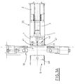
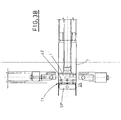
- Figures 3A, 3B, 3C are detailed views of particularly significant elements of the proposed device in subsequent, separate working steps related to the association of a tubular element to a corresponding support and to the definition of the tubular element bottom.
- With reference to the enclosed figures, the reference letter (D) indicates the device for fitting a tubular element (T) on a support (S) of complementary section, and for defining the bottom (F) of the tubular element, proposed by the present invention, as a whole.
- The device (D), as for example shown in Figure 1, is situated between a station (40) for feeding a film (21) of heat-weldable plastic material and an apparatus (70) for forming containers beginning from tubular elements obtained from the film (21).
- The apparatus (70) includes a conveying line (7), for example a chain, which has a plurality of equidistant supports (S), aimed at receiving and supporting corresponding tubular elements and at transferring them toward subsequent working stations for forming containers beginning from the tubular elements.
- The proposed device (D) includes a stationary element (2), of elongated shape, whose cross-section corresponds to the cross-section of the containers, which will be formed by the apparatus.
- The stationary element (2) is situated directly downstream of the outlet section of the station (40) feeding film (21) of plastic material.
- At this outlet section, there are means (22) for folding the film (21) and means (23) for winding the latter on the stationary element (2), so as to overlap the longitudinal edges of the film (21), in order to form a single tubular piece (20).
- Thus, the cross-section of the tubular piece (20) corresponds to the cross-section of the stationary element (2), and consequently to the cross-section of the containers to be obtained.
- Beside the tubular piece (20), there are welding means (24), which weld the above mentioned overlapped longitudinal edges, in order to complete the closure of the lateral surface of the piece (20).
- The welding means (24) are not shown in detail in the proposed figures, because they are known.
- The longitudinal dimensions of the stationary element (2) are such, as to define a corresponding tubular piece (20), which includes, in a single body, a series of single and subsequent tubular elements (T), whose longitudinal dimensions substantially correspond to those of the supports (S), on which they will be fitted.
- Therefore, the particular feature of the proposed device (D) lies in the fact that it transfers and fits the single tubular elements (T) on the corresponding supports, and at the same time, separates them from the single piece (20), in a completely automatic and mechanized way.
- For this purpose, the device (D) includes a moving member (1), which is connected to the stationary element (2), in the region of the end of the latter turned toward the containers forming apparatus (70), and which is aimed at acting on a first end (T1) of a tubular element (T), situated at one end of the piece (20), in order to transfer the latter to a proximal end (SP) of a relative support (S) and to allow the tubular element (T) to be fitted thereon, so that the relative first end (T1) result to be situated in the region of the distal end (SD) of the support (S) and the relative second end (T2) is situated near the proximal end (SP) of the support (S).
- The device (D) includes also means (10) for folding the second end (T2) onto the proximal end (SP) of the support (S) and for welding the second end (T2), in order to define a bottom (F) of the tubular element (T) (see Figure 2).
- The folding and welding means (10) are connected to suitable cutting means (11), aimed at cutting the second end (T2) of the tubular element (T) fitted on the support (S) from the piece (20), that is from the subsequent tubular element (T), comprised in the piece (20), to be fitted on a subsequent support (S) of the apparatus.
- According to the embodiment shown in the enclosed figures, the folding and welding means (10), as well as the cutting means (11), are supported by a pair of arms, set one opposite to the other in a normally open configuration, and aimed at being set closed to each other when the tubular element (T) is positioned on the relative support (S), as it will be more precisely described in the following.
- As shown in detail in Figures 3A, 3B and 3C, the moving member (1) is connected to the stationary element (2), so as to translate from a rear position (1R) (Figure 2, Figure 3C), in which it is situated substantially beside the end of the stationary element (2) facing the containers forming apparatus, and a fore position (1A) (Figure 3B), in which it substantially touches the proximal end (SP) of the support (S), in order to allow the tubular element (T) to be fitted on the support.
- The moving member (1) translates also from the fore position (1A) to the rear position (1R), so as to allow the second end (T2) of the tubular element (T) to be folded and welded, in order to define the relative bottom (F), and to cut the second end (T2) from the piece (20).
- Then the moving member (1) is ready for transferring a subsequent tubular element (T) of the piece (20) to a subsequent support (S).
- It is to be pointed out that, after the second end (T2) of the tubular element (T) fitted on the support (S) has been cut from the piece (20), the extreme fore portion (30) of the latter remains folded: for this purpose, the moving member (1) has a first plurality of holes (41), situated in its extreme fore portion and connected to a source of compressed air (not shown).
- The source of compressed air is activated to feed compressed air to the first plurality of holes (41) in step relation with the movement of the moving member (1) from the rear position (1R) to the fore position (1A), in order to translate the subsequent tubular element (T) of the piece toward the corresponding support (S), so as to widen the extreme folded portion (30) to re-shape it according to the corresponding tubular shape (see Figure 3A, which shows the moment, in which the moving member (1), during its translation to the fore position (1A), reaches the end of the extreme portion (30), which constitutes the first end of the subsequent tubular element (T)).
- The moving member (1) is connected to the stationary element (2) by a reciprocating stem (3), responsible for the alternate movement of the moving member (1) from the rear position (1R) to the fore position (1A).
- Further, the moving member (1), as well as the stationary element (2) have the same cross-section, corresponding to the cross-section required for the containers and complementary to the one of the supports (S).
- The device (D) is also equipped with means (5) for translating the piece (20), aimed at being operated synchronously with the moving member (1), in order to cooperate therewith to translate the tubular element (T) to the support (S) and to fit the tubular element (T) on the support (S).
- In particular, during normal operation of the device (D), the translation means (5) are operated when the moving member (1) reaches the end of the extreme portion (30) of the piece (20), during the translation of the latter from the rear position (1R) to the fore position (1A) (see Figure 3A).
- The translating means (5) include pairs of endless belts (51), situated on opposite sides of the stationary element (2), so that the relative working runs (52) touch directly the outer lateral surface of the tubular piece (20).
- The working runs (52) of the pairs of belts (51) are operated by relative operating rolls in the same forward movement direction.
- The translation means (5) are deactivated when the first end (T1) of the tubular element (T) is positioned at the distal end (SD) of the support (S) and are kept inoperative during the return of the moving member (1) from its fore position (1A) to its rear position (1R).
- The apparatus (70) for forming containers includes, in known way, transferring means (6), connected laterally to the supports (S) and facilitating the translation and the sliding of the tubular element (T) on the support, cooperating with the action of the translation means (5).
- In order to facilitate a more efficient sliding of the tubular element (T) on the support (S), the moving member (1) features a second plurality of holes (42) connected to the source of compressed air.
- The holes (42) are fed by the source of compressed air in step relation with the reaching, by the moving member (1), of the fore position (1A), in order to dilate and widen the tubular element (T) with respect to the support (S), thus creating a kind of air pad between them, which considerably reduces the friction that could be created between the inner surface of the tubular element (T) and the outer surface of the support (S).
- This facilitates the sliding of the tubular element (T) with respect to the support (S), making faster the positioning of the first end (T1) of the tubular element (T) in correspondence to the distal end (SD) of the support (S).
- As shown for example in Figure 3A, the above mentioned first plurality of holes (41) is made on the lateral surface of the end of the moving member (1), which can have a tapered shape, while the second plurality of holes (42) is made on the lateral surface of the moving member (1), near its end.
- Moreover, the supports (S) of the conveying line can have a plurality of holes (SF), likewise connected to a source of compressed air, to facilitate bigger dilation of the tubular element (T) during its sliding on the support (S).
- The operation of the proposed device is now described, beginning from the positioning of the first tubular element (T) of the piece (20) on a relative support (S) and taking into consideration the working sequences of Figures 3A, 3B and 3C, which show in detail the most significant steps and characteristics of the device working.
- The arms supporting the folding and welding means (10) and the cutting means (11) are open, the conveying line of the apparatus (70) has positioned a relative support (S) opposite to the stationary element (2) of the device (D) and the moving member (1) is operated to translate from the rear position (1R) to the fore position (1A).
- In step relation, and synchronously with the translation of the moving member (1), the translation means (5) are operated: the combination of the operation of the moving member (1) and of the translation means (5) allows the first tubular element (T) of the piece (20) to move toward the corresponding support (S), on which it is to be fitted.
- The moving member (1) reaches, as shown in Figure 3B, the support (S), accompanying the first end (T1) of the tubular element (T) to the proximal end (SP) of the support (S).
- The source of compressed air is activated to feed the second plurality of holes (42) to dilate and widen the tubular element (T) with respect to the support (S), so as to allow the translation means (5) to make the tubular element (T) slide, and consequently fit on the support (S) rapidly and easily, until the first end (T1) of the tubular element (T) reaches the distal end (SD) of the support (S).
- In order to facilitate the sliding of the tubular element (T) on the support (S), also the transferring means (6) are operated and the holes (SF) are fed by the relative source (of) compressed air.
- The translation means (5) and the transferring means are then stopped, the source of compressed air of the second plurality of holes (42) is deactivated, and so is the source of compressed air of the holes (SF), the moving member (1) returns from the fore position (1A) to the rear position (1R) and the arms supporting the folding and welding means (10) and the cutting means (11) are tightened (see in detail Figure 3C).
- In this way, the second end (T2) of the tubular element (T) is folded on the proximal end (SP) of the support (S) and welded, to define the bottom (F) of the tubular element (T), and the tubular element (T) is cut from the piece (20), that is from the subsequent tubular element (T) comprised in the piece (20).
- As it can be seen from Figure 3C, due to the above operations, the extreme fore portion (30) of the piece (20), which constitutes the first end of the subsequent tubular element (T) to be fitted on a subsequent support of the apparatus (70) and to be cut from the piece (20), is folded on itself as a result of the previous operating of the folding means.
- Therefore, during the initial step of the translation of the moving member (1) from the rear position (1R) to the fore position (1A), the source of compressed air is activated to feed the first plurality of holes (41), in order to open the folded extreme portion (30), re-shaping it on the moving member (1) and giving it again the corresponding cross-section.
- At the moment, in which the end of the moving member (1) reaches the end of the extreme portion (30) of the piece (20), completing its re-shaping according to the corresponding section (configuration shown in Figure 3A), the translation means (5) are activated, and the above described steps are repeated in order to fit the tubular element on the corresponding support and to define a relative bottom.
- It results obvious from the above description that the proposed device allows, advantageously to make automatic and mechanized the operations necessary to fit single and subsequent tubular elements on corresponding supports of an apparatus for forming containers, which results in the increase of the apparatus productive performance.
- Further, the proposed device allows also to define the bottom of tubular elements fitted on the relative supports by simple and rapid operation.
- The device subject of the present invention turns out to be particularly reliable and functional in any operation condition and in relation to the requested performances.
- According to the previously described embodiment, the shearing step in which the tubular element is cut from the piece is carried out while the tubular element is also folded and welded; in accordance with operational needs, such shearing can be made before transferring the tubular element, and before the operation of the moving member from the rear position' (1R) to the fore position (1A) and directly on the stationary element (2).
- Anyway, such particular embodiment is to be considered included within the scope of the present invention.
Claims (14)
- Device for fitting a tubular element on a support of complementary cross section, and for defining the bottom of such tubular element, characterized in that it includes a moving member (1) that has a plurality of holes for compressed air, and which is designed for acting on a first end (T1) of said tubular element (T) in order to transfer the latter to a proximal end (SP) of a related support (S) to allow the tubular element (T) to be fitted on said support (S), so that said first end (T1) of said tubular element (T) result to be situated at the distal end (SD) of the support (S) and a second end (T2) of the same tubular element (T) is situated near the proximal end (SP) of the support (S), and in that it includes means (10) for folding and welding said second end (T2) in order to define a bottom (F) of the tubular element (T).
- Device according to claim 1, characterized in that it includes a stationary element (2), of elongated shape, disposed upstream of said moving member (1), and with a cross-section corresponding to the cross-section of said tubular element (T), said stationary member being designed for receiving, fitted thereon, a single tubular piece (20) obtained from a thermo-weldable plastic material film (21) by folding means (22) and winding means (23) for winding the film onto a stationary element (2) with overlapped longitudinal edges, which edges are then welded to one another by welding means (24), said single tubular piece (20) including a series of adjacent tubular elements, as a single unit, which are to be fitted onto respective supports (S), said tubular element (T) forming the advanced extreme portion of said piece (20).
- Device according to claim 2, characterized in that it includes cutting means (11), joined to said folding and thermo-welding means (10), for cutting said second end (T2) of the tubular element (T) away form said piece (20) in phase relation with positioning of said first end (T1) of the tubular element (T) at said distal end (SD) of said support (S).
- Device according to claim 3, characterized in that said moving member (1) is joined to said stationary element (2) in such a way that it can shift from a rear position (1R), in which it is situated substantially beside one end of the stationary element (2), to a fore position (1A), in which it substantially touches the said proximal end (SP) of the support (S), in order to allow the tubular element (T) to be fitted on the support, and vice-versa, from the fore position (1A) to the rear position (1R), so as to allow the second end (T2) of the tubular element (T) to be folded and welded, and to allow the second end (T2) to be cut from the piece (20), in order to define the said bottom (F) and for transferring a subsequent tubular element (T) of the piece (20) to said support (S), the extreme fore portion (30) of the latter remaining folded due to the shearing of the previous tubular element (T) away from the piece (20).
- Device according to claim 4, characterized in that said moving member (1) is joined to said stationary element (2) by means of a reciprocating stem (3).
- Device according to claim 4, characterized in that it includes means (5) for translating the piece (20), which translating means are operated synchronously with the moving member (1), during the shift of this letter from the rear position (1R) to said fore position (1A), in order to cooperate with said moving member (1) for moving the tubular element (T) to the support (S) and to fit the tubular element (T) on the support (S).
- Device according to claim 6, characterized in that the said translating means (5) include pairs of endless belts (51), situated on opposite sides of the stationary element (2), and acting with a relative runs (52) directly the outer lateral surface of the tubular piece (20).
- Device according to claim 4, characterized in that said moving member (1) has a first plurality of holes (41) which are fed with compressed air from a source of compressed air, so as to widen the extreme folded portion (30) of the subsequent tubular element (T) of the piece (20) to be fitted onto a related support (S) and for re-shape it according to the corresponding tubular shape
- Device according to claim 8, characterized in that said first plurality of holes (41) is fed by said source of compressed air in step relation with the initial stage of movement of the moving member (1) from the rear position (1R) to the fore position (1A),
- Device according to claim 4, characterized in that the said moving member (1) features also a second plurality of holes (42), which are fed by a source of compressed air to dilate and widen the tubular element (T), in step relation with the reaching, by the moving member (1), of the fore position (1A), so as to facilitates the sliding of the tubular element (T) with respect to the support (S), thus allowing the same tubular element (T) to fit easily and quickly said support (S).
- Device according to claim 3, characterized in that the folding and welding means (10), as well as the cutting means (11), are supported by a pair of arms, set one opposite to the other in a normally open configuration, and aimed at being set closed to each other when the said first end (T1) of the tubular element (T) is positioned at said distal end (SD) of said support (S), in order to perform folding and welding of said second end (T2) of the tubular element (T) and to define said bottom (F) and to shear said second end away from the extreme fore end of a subsequent tubular element (T) of said piece (20).
- Device according to claim 2, characterized in that said moving member (1) and said stationary element (2) have relevant cross-sections corresponding to the cross-section of said support (S).
- Device according to claim 2, characterized in that said moving member (1) is associated with said stationary element (2) in such a way that it can operate internally within said tubular element (T), along the lateral internal surface of this latter.
- Device according to any one of the previous claims, characterized in that said device is located between a feeding station for feeding a film of plastic thermo-weldable material, and an apparatus for manufacturing containers from tubular elements fitted onto relevant supports.
Applications Claiming Priority (2)
| Application Number | Priority Date | Filing Date | Title |
|---|---|---|---|
| ITBO20020733 | 2002-11-20 | ||
| ITBO20020733 ITBO20020733A1 (en) | 2002-11-20 | 2002-11-20 | DEVICE TO FIT A TUBULAR ELEMENT ON A SUPPORT OF A COMPLEMENTARY SECTION AND TO DEFINE THE BOTTOM OF SUCH A TUBULAR ELEMENT |
Publications (2)
| Publication Number | Publication Date |
|---|---|
| EP1422053A1 EP1422053A1 (en) | 2004-05-26 |
| EP1422053B1 true EP1422053B1 (en) | 2006-08-16 |
Family
ID=32211374
Family Applications (1)
| Application Number | Title | Priority Date | Filing Date |
|---|---|---|---|
| EP20030026588 Expired - Lifetime EP1422053B1 (en) | 2002-11-20 | 2003-11-19 | Device for fitting a tubular element on a support of a complementary cross section and for defining a bottom of the tubular element |
Country Status (5)
| Country | Link |
|---|---|
| EP (1) | EP1422053B1 (en) |
| AT (1) | ATE336360T1 (en) |
| DE (1) | DE60307577D1 (en) |
| ES (1) | ES2271457T3 (en) |
| IT (1) | ITBO20020733A1 (en) |
Family Cites Families (3)
| Publication number | Priority date | Publication date | Assignee | Title |
|---|---|---|---|---|
| DE1227324B (en) * | 1962-12-24 | 1966-10-20 | Holstein & Kappert Maschf | Device for stripping paper bags or the like from an expanding mandrel |
| ITBO20000543A1 (en) * | 2000-09-19 | 2002-03-19 | Curti Costruzioni Meccaniche S | MACHINE AND METHOD FOR FORMING A CONTAINER STARTING FROM A BAND OF TAPE MATERIAL |
| US20030054929A1 (en) * | 2001-09-19 | 2003-03-20 | Post William E. | Flat bottom, stand up bag and method of manufacturing the same |
-
2002
- 2002-11-20 IT ITBO20020733 patent/ITBO20020733A1/en unknown
-
2003
- 2003-11-19 DE DE60307577T patent/DE60307577D1/en not_active Expired - Lifetime
- 2003-11-19 AT AT03026588T patent/ATE336360T1/en not_active IP Right Cessation
- 2003-11-19 ES ES03026588T patent/ES2271457T3/en not_active Expired - Lifetime
- 2003-11-19 EP EP20030026588 patent/EP1422053B1/en not_active Expired - Lifetime
Also Published As
| Publication number | Publication date |
|---|---|
| ITBO20020733A1 (en) | 2004-05-21 |
| ATE336360T1 (en) | 2006-09-15 |
| ES2271457T3 (en) | 2007-04-16 |
| EP1422053A1 (en) | 2004-05-26 |
| DE60307577D1 (en) | 2006-09-28 |
Similar Documents
| Publication | Publication Date | Title |
|---|---|---|
| DE68925981T2 (en) | Packaging machine and process | |
| EP2230067B2 (en) | Machine and method for producing rolls of pre-cut bags with die-cut handles | |
| EP0269145B1 (en) | Apparatus for packaging products | |
| US20100022375A1 (en) | Method for the Production of Packaging Bags Having a Reinforced Base Region and Device for Carrying Out the Method | |
| US4386924A (en) | Handle bag making apparatus | |
| KR20010042919A (en) | A method and a system for filling goods in bags from a coherent series of bag members | |
| US5634324A (en) | Bag making machine | |
| US6117060A (en) | Continuous supply of preformed reclosable fasteners | |
| US6966164B2 (en) | Tubular banding applicator and method | |
| WO2007106916A1 (en) | Continuous motion vertical form, fill and seal machine | |
| GB2298850A (en) | A stand-up pack | |
| EP1422053A1 (en) | Device for fitting a tubular element on a support of a complementary cross section and for defining a bottom of the tubular element | |
| US4469542A (en) | Method of making a piece of tube from a flat web of flexible material, and apparatus for carrying out the method | |
| US4588120A (en) | Apparatus and method for forming belt loops and the like | |
| US3783751A (en) | Methods and apparatus for making sacks or bags | |
| US4203270A (en) | High speed tear tape applicator for shrink wrap film packaging | |
| US5626706A (en) | Method and apparatus for preparing strip material | |
| CZ291679B6 (en) | Transverse sealing device in a tubular bag forming machine | |
| US4558653A (en) | Label advancing system for a line closer machine | |
| WO1994021449A1 (en) | Apparatus and method for applying a twist-tie to a packaging container | |
| US3502536A (en) | Mechanism for producing tear strips | |
| JPS5850866B2 (en) | How to make cross-bottom bags | |
| US2023147A (en) | Wrapping machine | |
| JP2001294202A (en) | Automatic filling and packaging machine | |
| US4308022A (en) | Apparatus for binding smoking casings |
Legal Events
| Date | Code | Title | Description |
|---|---|---|---|
| PUAI | Public reference made under article 153(3) epc to a published international application that has entered the european phase |
Free format text: ORIGINAL CODE: 0009012 |
|
| AK | Designated contracting states |
Kind code of ref document: A1 Designated state(s): AT BE BG CH CY CZ DE DK EE ES FI FR GB GR HU IE IT LI LU MC NL PT RO SE SI SK TR |
|
| AX | Request for extension of the european patent |
Extension state: AL LT LV MK |
|
| 17P | Request for examination filed |
Effective date: 20041122 |
|
| AKX | Designation fees paid |
Designated state(s): AT BE BG CH CY CZ DE DK EE ES FI FR GB GR HU IE IT LI LU MC NL PT RO SE SI SK TR |
|
| GRAP | Despatch of communication of intention to grant a patent |
Free format text: ORIGINAL CODE: EPIDOSNIGR1 |
|
| GRAS | Grant fee paid |
Free format text: ORIGINAL CODE: EPIDOSNIGR3 |
|
| GRAA | (expected) grant |
Free format text: ORIGINAL CODE: 0009210 |
|
| AK | Designated contracting states |
Kind code of ref document: B1 Designated state(s): AT BE BG CH CY CZ DE DK EE ES FI FR GB GR HU IE IT LI LU MC NL PT RO SE SI SK TR |
|
| PG25 | Lapsed in a contracting state [announced via postgrant information from national office to epo] |
Ref country code: IT Free format text: LAPSE BECAUSE OF FAILURE TO SUBMIT A TRANSLATION OF THE DESCRIPTION OR TO PAY THE FEE WITHIN THE PRESCRIBED TIME-LIMIT;WARNING: LAPSES OF ITALIAN PATENTS WITH EFFECTIVE DATE BEFORE 2007 MAY HAVE OCCURRED AT ANY TIME BEFORE 2007. THE CORRECT EFFECTIVE DATE MAY BE DIFFERENT FROM THE ONE RECORDED. Effective date: 20060816 Ref country code: NL Free format text: LAPSE BECAUSE OF FAILURE TO SUBMIT A TRANSLATION OF THE DESCRIPTION OR TO PAY THE FEE WITHIN THE PRESCRIBED TIME-LIMIT Effective date: 20060816 Ref country code: CH Free format text: LAPSE BECAUSE OF FAILURE TO SUBMIT A TRANSLATION OF THE DESCRIPTION OR TO PAY THE FEE WITHIN THE PRESCRIBED TIME-LIMIT Effective date: 20060816 Ref country code: SI Free format text: LAPSE BECAUSE OF FAILURE TO SUBMIT A TRANSLATION OF THE DESCRIPTION OR TO PAY THE FEE WITHIN THE PRESCRIBED TIME-LIMIT Effective date: 20060816 Ref country code: CZ Free format text: LAPSE BECAUSE OF FAILURE TO SUBMIT A TRANSLATION OF THE DESCRIPTION OR TO PAY THE FEE WITHIN THE PRESCRIBED TIME-LIMIT Effective date: 20060816 Ref country code: FI Free format text: LAPSE BECAUSE OF FAILURE TO SUBMIT A TRANSLATION OF THE DESCRIPTION OR TO PAY THE FEE WITHIN THE PRESCRIBED TIME-LIMIT Effective date: 20060816 Ref country code: SK Free format text: LAPSE BECAUSE OF FAILURE TO SUBMIT A TRANSLATION OF THE DESCRIPTION OR TO PAY THE FEE WITHIN THE PRESCRIBED TIME-LIMIT Effective date: 20060816 Ref country code: BE Free format text: LAPSE BECAUSE OF FAILURE TO SUBMIT A TRANSLATION OF THE DESCRIPTION OR TO PAY THE FEE WITHIN THE PRESCRIBED TIME-LIMIT Effective date: 20060816 Ref country code: RO Free format text: LAPSE BECAUSE OF FAILURE TO SUBMIT A TRANSLATION OF THE DESCRIPTION OR TO PAY THE FEE WITHIN THE PRESCRIBED TIME-LIMIT Effective date: 20060816 Ref country code: AT Free format text: LAPSE BECAUSE OF FAILURE TO SUBMIT A TRANSLATION OF THE DESCRIPTION OR TO PAY THE FEE WITHIN THE PRESCRIBED TIME-LIMIT Effective date: 20060816 Ref country code: LI Free format text: LAPSE BECAUSE OF FAILURE TO SUBMIT A TRANSLATION OF THE DESCRIPTION OR TO PAY THE FEE WITHIN THE PRESCRIBED TIME-LIMIT Effective date: 20060816 |
|
| REG | Reference to a national code |
Ref country code: GB Ref legal event code: FG4D |
|
| REG | Reference to a national code |
Ref country code: CH Ref legal event code: EP |
|
| REG | Reference to a national code |
Ref country code: IE Ref legal event code: FG4D |
|
| REF | Corresponds to: |
Ref document number: 60307577 Country of ref document: DE Date of ref document: 20060928 Kind code of ref document: P |
|
| PG25 | Lapsed in a contracting state [announced via postgrant information from national office to epo] |
Ref country code: DK Free format text: LAPSE BECAUSE OF FAILURE TO SUBMIT A TRANSLATION OF THE DESCRIPTION OR TO PAY THE FEE WITHIN THE PRESCRIBED TIME-LIMIT Effective date: 20061116 Ref country code: SE Free format text: LAPSE BECAUSE OF FAILURE TO SUBMIT A TRANSLATION OF THE DESCRIPTION OR TO PAY THE FEE WITHIN THE PRESCRIBED TIME-LIMIT Effective date: 20061116 Ref country code: BG Free format text: LAPSE BECAUSE OF FAILURE TO SUBMIT A TRANSLATION OF THE DESCRIPTION OR TO PAY THE FEE WITHIN THE PRESCRIBED TIME-LIMIT Effective date: 20061116 |
|
| PG25 | Lapsed in a contracting state [announced via postgrant information from national office to epo] |
Ref country code: DE Free format text: LAPSE BECAUSE OF FAILURE TO SUBMIT A TRANSLATION OF THE DESCRIPTION OR TO PAY THE FEE WITHIN THE PRESCRIBED TIME-LIMIT Effective date: 20061117 |
|
| PG25 | Lapsed in a contracting state [announced via postgrant information from national office to epo] |
Ref country code: IE Free format text: LAPSE BECAUSE OF NON-PAYMENT OF DUE FEES Effective date: 20061120 |
|
| PG25 | Lapsed in a contracting state [announced via postgrant information from national office to epo] |
Ref country code: MC Free format text: LAPSE BECAUSE OF NON-PAYMENT OF DUE FEES Effective date: 20061130 |
|
| PG25 | Lapsed in a contracting state [announced via postgrant information from national office to epo] |
Ref country code: PT Free format text: LAPSE BECAUSE OF FAILURE TO SUBMIT A TRANSLATION OF THE DESCRIPTION OR TO PAY THE FEE WITHIN THE PRESCRIBED TIME-LIMIT Effective date: 20070116 |
|
| NLV1 | Nl: lapsed or annulled due to failure to fulfill the requirements of art. 29p and 29m of the patents act | ||
| REG | Reference to a national code |
Ref country code: CH Ref legal event code: PL |
|
| REG | Reference to a national code |
Ref country code: ES Ref legal event code: FG2A Ref document number: 2271457 Country of ref document: ES Kind code of ref document: T3 |
|
| EN | Fr: translation not filed | ||
| PLBE | No opposition filed within time limit |
Free format text: ORIGINAL CODE: 0009261 |
|
| STAA | Information on the status of an ep patent application or granted ep patent |
Free format text: STATUS: NO OPPOSITION FILED WITHIN TIME LIMIT |
|
| 26N | No opposition filed |
Effective date: 20070518 |
|
| PG25 | Lapsed in a contracting state [announced via postgrant information from national office to epo] |
Ref country code: FR Free format text: LAPSE BECAUSE OF FAILURE TO SUBMIT A TRANSLATION OF THE DESCRIPTION OR TO PAY THE FEE WITHIN THE PRESCRIBED TIME-LIMIT Effective date: 20070511 Ref country code: GR Free format text: LAPSE BECAUSE OF FAILURE TO SUBMIT A TRANSLATION OF THE DESCRIPTION OR TO PAY THE FEE WITHIN THE PRESCRIBED TIME-LIMIT Effective date: 20061117 |
|
| PG25 | Lapsed in a contracting state [announced via postgrant information from national office to epo] |
Ref country code: EE Free format text: LAPSE BECAUSE OF FAILURE TO SUBMIT A TRANSLATION OF THE DESCRIPTION OR TO PAY THE FEE WITHIN THE PRESCRIBED TIME-LIMIT Effective date: 20060816 |
|
| GBPC | Gb: european patent ceased through non-payment of renewal fee |
Effective date: 20071119 |
|
| PG25 | Lapsed in a contracting state [announced via postgrant information from national office to epo] |
Ref country code: LU Free format text: LAPSE BECAUSE OF NON-PAYMENT OF DUE FEES Effective date: 20061119 Ref country code: TR Free format text: LAPSE BECAUSE OF FAILURE TO SUBMIT A TRANSLATION OF THE DESCRIPTION OR TO PAY THE FEE WITHIN THE PRESCRIBED TIME-LIMIT Effective date: 20060816 Ref country code: HU Free format text: LAPSE BECAUSE OF FAILURE TO SUBMIT A TRANSLATION OF THE DESCRIPTION OR TO PAY THE FEE WITHIN THE PRESCRIBED TIME-LIMIT Effective date: 20070217 |
|
| PG25 | Lapsed in a contracting state [announced via postgrant information from national office to epo] |
Ref country code: FR Free format text: LAPSE BECAUSE OF FAILURE TO SUBMIT A TRANSLATION OF THE DESCRIPTION OR TO PAY THE FEE WITHIN THE PRESCRIBED TIME-LIMIT Effective date: 20060816 Ref country code: CY Free format text: LAPSE BECAUSE OF FAILURE TO SUBMIT A TRANSLATION OF THE DESCRIPTION OR TO PAY THE FEE WITHIN THE PRESCRIBED TIME-LIMIT Effective date: 20060816 |
|
| PG25 | Lapsed in a contracting state [announced via postgrant information from national office to epo] |
Ref country code: GB Free format text: LAPSE BECAUSE OF NON-PAYMENT OF DUE FEES Effective date: 20071119 |
|
| PGFP | Annual fee paid to national office [announced via postgrant information from national office to epo] |
Ref country code: IT Payment date: 20151125 Year of fee payment: 13 |
|
| PGFP | Annual fee paid to national office [announced via postgrant information from national office to epo] |
Ref country code: ES Payment date: 20151124 Year of fee payment: 13 |
|
| PG25 | Lapsed in a contracting state [announced via postgrant information from national office to epo] |
Ref country code: IT Free format text: LAPSE BECAUSE OF NON-PAYMENT OF DUE FEES Effective date: 20161119 |
|
| PG25 | Lapsed in a contracting state [announced via postgrant information from national office to epo] |
Ref country code: ES Free format text: LAPSE BECAUSE OF NON-PAYMENT OF DUE FEES Effective date: 20161120 |
|
| REG | Reference to a national code |
Ref country code: ES Ref legal event code: FD2A Effective date: 20181120 |