EP1420967B1 - Wheel suspension - Google Patents
Wheel suspension Download PDFInfo
- Publication number
- EP1420967B1 EP1420967B1 EP02765732A EP02765732A EP1420967B1 EP 1420967 B1 EP1420967 B1 EP 1420967B1 EP 02765732 A EP02765732 A EP 02765732A EP 02765732 A EP02765732 A EP 02765732A EP 1420967 B1 EP1420967 B1 EP 1420967B1
- Authority
- EP
- European Patent Office
- Prior art keywords
- wheels
- wheel suspension
- elements
- wheel
- vehicle
- Prior art date
- Legal status (The legal status is an assumption and is not a legal conclusion. Google has not performed a legal analysis and makes no representation as to the accuracy of the status listed.)
- Expired - Lifetime
Links
- 239000000725 suspension Substances 0.000 title claims abstract description 49
- 230000006835 compression Effects 0.000 claims description 8
- 238000007906 compression Methods 0.000 claims description 8
- 239000012528 membrane Substances 0.000 claims description 7
- 239000010720 hydraulic oil Substances 0.000 claims description 5
- 230000000750 progressive effect Effects 0.000 claims description 3
- 241001272996 Polyphylla fullo Species 0.000 abstract description 2
- XEEYBQQBJWHFJM-UHFFFAOYSA-N Iron Chemical compound [Fe] XEEYBQQBJWHFJM-UHFFFAOYSA-N 0.000 description 14
- 229910052742 iron Inorganic materials 0.000 description 7
- 238000007789 sealing Methods 0.000 description 3
- 229910000639 Spring steel Inorganic materials 0.000 description 2
- 229910000831 Steel Inorganic materials 0.000 description 2
- 230000001965 increasing effect Effects 0.000 description 2
- 239000000463 material Substances 0.000 description 2
- 239000010959 steel Substances 0.000 description 2
- 238000003466 welding Methods 0.000 description 2
- 239000004809 Teflon Substances 0.000 description 1
- 229920006362 Teflon® Polymers 0.000 description 1
- 230000001464 adherent effect Effects 0.000 description 1
- 230000001419 dependent effect Effects 0.000 description 1
- 238000005553 drilling Methods 0.000 description 1
- 230000003028 elevating effect Effects 0.000 description 1
- 230000001552 evening effect Effects 0.000 description 1
- 238000004519 manufacturing process Methods 0.000 description 1
- 238000000034 method Methods 0.000 description 1
- 238000012986 modification Methods 0.000 description 1
- 230000004048 modification Effects 0.000 description 1
- 239000004033 plastic Substances 0.000 description 1
- 230000001902 propagating effect Effects 0.000 description 1
- 239000004575 stone Substances 0.000 description 1
Images




Classifications
-
- B—PERFORMING OPERATIONS; TRANSPORTING
- B60—VEHICLES IN GENERAL
- B60G—VEHICLE SUSPENSION ARRANGEMENTS
- B60G21/00—Interconnection systems for two or more resiliently-suspended wheels, e.g. for stabilising a vehicle body with respect to acceleration, deceleration or centrifugal forces
- B60G21/02—Interconnection systems for two or more resiliently-suspended wheels, e.g. for stabilising a vehicle body with respect to acceleration, deceleration or centrifugal forces permanently interconnected
- B60G21/04—Interconnection systems for two or more resiliently-suspended wheels, e.g. for stabilising a vehicle body with respect to acceleration, deceleration or centrifugal forces permanently interconnected mechanically
- B60G21/05—Interconnection systems for two or more resiliently-suspended wheels, e.g. for stabilising a vehicle body with respect to acceleration, deceleration or centrifugal forces permanently interconnected mechanically between wheels on the same axle but on different sides of the vehicle, i.e. the left and right wheel suspensions being interconnected
-
- B—PERFORMING OPERATIONS; TRANSPORTING
- B62—LAND VEHICLES FOR TRAVELLING OTHERWISE THAN ON RAILS
- B62B—HAND-PROPELLED VEHICLES, e.g. HAND CARTS OR PERAMBULATORS; SLEDGES
- B62B5/00—Accessories or details specially adapted for hand carts
- B62B5/02—Accessories or details specially adapted for hand carts providing for travelling up or down a flight of stairs
- B62B5/028—Accessories or details specially adapted for hand carts providing for travelling up or down a flight of stairs with excentrically mounted wheels
-
- A—HUMAN NECESSITIES
- A61—MEDICAL OR VETERINARY SCIENCE; HYGIENE
- A61G—TRANSPORT, PERSONAL CONVEYANCES, OR ACCOMMODATION SPECIALLY ADAPTED FOR PATIENTS OR DISABLED PERSONS; OPERATING TABLES OR CHAIRS; CHAIRS FOR DENTISTRY; FUNERAL DEVICES
- A61G5/00—Chairs or personal conveyances specially adapted for patients or disabled persons, e.g. wheelchairs
- A61G5/06—Chairs or personal conveyances specially adapted for patients or disabled persons, e.g. wheelchairs with obstacle mounting facilities, e.g. for climbing stairs, kerbs or steps
-
- A—HUMAN NECESSITIES
- A61—MEDICAL OR VETERINARY SCIENCE; HYGIENE
- A61G—TRANSPORT, PERSONAL CONVEYANCES, OR ACCOMMODATION SPECIALLY ADAPTED FOR PATIENTS OR DISABLED PERSONS; OPERATING TABLES OR CHAIRS; CHAIRS FOR DENTISTRY; FUNERAL DEVICES
- A61G5/00—Chairs or personal conveyances specially adapted for patients or disabled persons, e.g. wheelchairs
- A61G5/06—Chairs or personal conveyances specially adapted for patients or disabled persons, e.g. wheelchairs with obstacle mounting facilities, e.g. for climbing stairs, kerbs or steps
- A61G5/063—Chairs or personal conveyances specially adapted for patients or disabled persons, e.g. wheelchairs with obstacle mounting facilities, e.g. for climbing stairs, kerbs or steps with eccentrically mounted wheels
-
- B—PERFORMING OPERATIONS; TRANSPORTING
- B60—VEHICLES IN GENERAL
- B60G—VEHICLE SUSPENSION ARRANGEMENTS
- B60G2200/00—Indexing codes relating to suspension types
- B60G2200/30—Rigid axle suspensions
-
- B—PERFORMING OPERATIONS; TRANSPORTING
- B60—VEHICLES IN GENERAL
- B60G—VEHICLE SUSPENSION ARRANGEMENTS
- B60G2200/00—Indexing codes relating to suspension types
- B60G2200/40—Indexing codes relating to the wheels in the suspensions
- B60G2200/464—Caster angle
-
- B—PERFORMING OPERATIONS; TRANSPORTING
- B60—VEHICLES IN GENERAL
- B60G—VEHICLE SUSPENSION ARRANGEMENTS
- B60G2202/00—Indexing codes relating to the type of spring, damper or actuator
- B60G2202/10—Type of spring
- B60G2202/12—Wound spring
-
- B—PERFORMING OPERATIONS; TRANSPORTING
- B60—VEHICLES IN GENERAL
- B60G—VEHICLE SUSPENSION ARRANGEMENTS
- B60G2206/00—Indexing codes related to the manufacturing of suspensions: constructional features, the materials used, procedures or tools
- B60G2206/01—Constructional features of suspension elements, e.g. arms, dampers, springs
- B60G2206/30—Constructional features of rigid axles
- B60G2206/312—Cranked axle
-
- B—PERFORMING OPERATIONS; TRANSPORTING
- B60—VEHICLES IN GENERAL
- B60G—VEHICLE SUSPENSION ARRANGEMENTS
- B60G2300/00—Indexing codes relating to the type of vehicle
- B60G2300/22—Perambulators
-
- B—PERFORMING OPERATIONS; TRANSPORTING
- B60—VEHICLES IN GENERAL
- B60G—VEHICLE SUSPENSION ARRANGEMENTS
- B60G2300/00—Indexing codes relating to the type of vehicle
- B60G2300/24—Wheelchairs
-
- B—PERFORMING OPERATIONS; TRANSPORTING
- B60—VEHICLES IN GENERAL
- B60G—VEHICLE SUSPENSION ARRANGEMENTS
- B60G2300/00—Indexing codes relating to the type of vehicle
- B60G2300/40—Variable track or wheelbase vehicles
Definitions
- the present invention relates to a wheel suspension for vehicles.
- the invention relates to both multi axle vehicles and single axle vehicles.
- the following feasible areas of use may be mentioned: prams, pallet lifters, carts (pulled manually or by a vehicle), walkers, wheel chairs, lagguage carts, wheelbarrows and motor vehicles.
- the invention is applicable for relatively seen small wheels or compact wheel units that get stuck in cavities.
- the pram has a wheel suspension where the wheel carrying axis has an intermediate portion which is recessed relative to the portions of the axis that carry the wheels, this being the case when the pram is located on a planar ground. Said intermediate portion supports, via springs, the seat unit.
- the fundamental principle of the wheel suspension is that a pushing force upon the pram is, at least partly, transferred to an elevating force due to the fact that the intermediate portion rotates relative to the wheel carrying portions.
- a primary object of the present invention is to present a wheel suspension of the type defined above, said wheel suspension having an improved function as regards the compensation of the vertical movements that the wheels are subjected to when by-passing unevennesses in the ground that the wheels are travelling on. Thereby, an evened motion is achieved for the vehicle being equipped with the wheel suspension.
- a further object of the present invention is that the structural design of the wheel suspension should be simple and hence inexpensive to manufacture.
- Still an object of the present invention is that according to a preferred embodiment of the invention the wheel suspension has an inherent spring function.
- the pram chassis shown in figures 1 and 2 comprises a frame 1 that in its turn comprises two longitudinal first rods 3 and two transverse second rods 5, said first rods 3 and said second rods 5 being mutually connected in a suitable way, e.g. by means of welding, in order to provide a rigid frame 1 that is able to handle the forces acting on the frame 1.
- axle 7 In the area of both ends of the frame 1, seen in the longitudinal direction of the frame 1, an axle 7 is provided, said axle 7 constituting an essential element of the wheel suspension according to the present invention.
- the axle 7 comprises an intermediate portion 9 and two generally Z-shaped portions 10 that are provided at both ends of the intermediate portion 9.
- wheels 11a and 11b are rotatably mounted in a suitable way.
- the wheels that are located at the bottom in the top view according to figure 1 are designated 11a while the wheels that are located at the top in the top view according to figure 1 are designated 11b.
- the unit that is defined by the axle 7 and the wheels 11a and 11b is called a set of wheels.
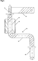
- the Z-shaped portion 10 is shown in detail.
- An inner portion 12 of the Z-shaped portion 10 is rotatably received in a bearing 13 that is supported by the frame 1.
- the bearing 13 is preferably a so-called teflon bearing.
- the Z-shaped portion 10 also includes an intermediate portion 14 that projects from the inner portion 12, and an outer portion 15 that projects from the end of the intermediate portion 14 that faces away from the inner portion 12. Since the portion 10 generally is Z-shaped the intermediate portion 14 has a longitudinal direction that extends transverse to the longitudinal direction of the inner portion 12 and the outer portion 15 has a longitudinal direction that extends transverse to the longitudinal direction of the intermediate portion 14.
- the longitudinal direction of the intermediate portion 14 is perpendicular to the longitudinal direction of the inner portion 12 and the outer portion 15 and the longitudinal directions of the inner portion 12 and the outer portion 15 are parallel.
- a wheel (not shown in figure 3) is mounted, said wheel being rotatable relative to the outer portion 15.
- the intermediate portion 14 has an extension in the longitudinal direction/travelling direction of the pram, said direction being illustrated by the double arrow 2 in figures 1 and 2.
- connection between the Z-shaped portion 10 and the intermediate portion 9 should be rigid. Said connection is preferably achieved by drilling and welding.
- the intermediate portion 9 is preferably manufactured from spring steel while the Z-shaped portion 10 preferably is manufactured from a stiffer steel quality. The importance of this will be explained below in connection with the description of the function of the wheel suspension.
- an iron flat 16 is rigidly attached at the middle of each intermediate portion 9.
- a first spring 17 is mounted between the iron flat 16 and the adherent transverse second rod 5. The function of the arrangement with the iron flat 16 and the first springs 17 will be described below.
- the first springs 17 constitute tension springs.
- the frame 1' has a different design compared to the frame 1.
- the frame 1' comprises two sub-frames that are only partly shown in figures 4 and 5. In areas where they cross each other the sub frames 1' are in a conventional way hingedly connected to each other.
- the groove 18 has such a width that the wheel 11a that travels at the front in the longitudinal direction/travelling direction of the pram remains hanging in the air due to the structural design of the wheel suspension according to the present invention.
- the longitudinal direction/travelling direction is illustrated by the arrow 2 in figures 6a-6c.
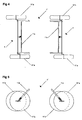
- An extremely important feature of the wheel suspension according to the present invention is the fact that the intermediate portion 9 of the axle 7 only moves downwards about half the distance that the centre axle 15a moves downwards, this being evident from figure 6a, where the distance that the intermediate portion 9 moves downwards is designated by d/2.
- figure 6b it is shown how the pair of wheels 11a, 11b is located in the middle of the groove 18 and respective wheels 11a, 11b abut the opposite edges of the groove 18.
- a conventional pair of wheels behaves when passing the groove 18, the wheel in this case being dotted along its entire circumference.
- the conventional pair of wheels said pair being symbolised by the dotted wheel, will descend into the groove 18 to an essentially larger degree than the pair of wheels 11a, 11b according to the present invention.
- the distance that the conventional pair of wheels moves downwards in the groove 18 has been designated by "e" in figure 6b.
- FIG 6a-6c it is illustrated the case when the front wheel 11a runs down in a groove 18 or the like.
- the wheel suspension according to the present invention functions equal well if the front wheel 11a runs over an elevation in the ground. In such a case the front wheel 11a will be raised relative to the rear wheel 11b.
- the wheel suspension will function in principally the same way as regards the evening effect upon unevennesses in the ground.
- the structure shown in figure 6 should be equipped with some kind of deflection limiter to prevent the wheel suspension from tilting to one side in an uncontrolled manner if a large load is applied to said side.
- some kind of deflection limiter to prevent the wheel suspension from tilting to one side in an uncontrolled manner if a large load is applied to said side.
- the type of deflection limiter that is shown in the embodiments described below.
- the deflection limiter is integral with the spring in such a way that the spring is allowed to be extended/compressed only a certain distance before it reaches a stop.
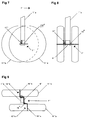
- the wheel suspension according to the present invention that is schematically shown in figures 7-9 is applied to a set of wheels comprising a pair of wheels of a so-called umbrella stroller.
- an axle 7" is rotatably attached to a rear sub-frame 1"a of the umbrella stroller, said axle 7" having a intermediate straight portion 9".
- the umbrella stroller comprises for such sub-frames that are included in the frame of the umbrella stroller.
- the axle 7" also comprises two Z-shaped portions 10"a and 10"b respectively, that are arranged at respective ends of the intermediate portion 9".
- Each of the Z-shaped portions 10" comprises an outer portion 15"a and 15"b respectively that are parallel to the intermediate portion 9".
- a first compression spring 17 preferably a progressive compression spring, is mounted between the axle 7" and a fixed bracket on the sub-frame 1"a.
- the first compression spring 17" has principally the same function as the first tension spring 17 in the embodiments described above, however with the difference that the lower end of the compression spring 17" is not attached to the axle 7". This means that when the front wheel 11"a enters a curb or the like the portion of the axle 7" that is located directly opposite the compression spring 17", i.e.
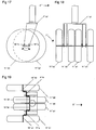
- FIG. 10-12 and figures 13a-13c a further alternative embodiment is shown where three wheels 11"'a, 11"'b, 11"'c define a set of wheels.
- the ⁇ -axle 7"' that carries the wheels 11"'a, 11"'b, 11"'c constitutes in principle two assembled Z-axles and the centrally located centre axle 15"'b of the axle 7"' is displaced in the longitudinal direction/travelling direction 2"' of the vehicle relative to the two other centre axles 15"'a and 15"'c.
- the axle 7"' is pivotally suspended in a sub-frame 1"'a by means of pins 8"'.
- two stops 19"'b and 19"'c are attached to the sub-frame 1"'a in order to limit the pivoting of the axle 7"'.
- FIGa-13c it is schematically illustrated how the set of wheels in the embodiment according to figures 10-12 behaves when it passes an upright obstacle 27.
- the wheel 11"'b travelling first in the longitudinal direction/travelling direction 2 of the vehicle will move upwards as it looses its contact with the ground, see figure 13a.
- the stop 19"'b guarantees that there is no uncontrolled rotation of the front wheel 11"'b relative to the rear wheels 11"'a and 11"'c.
- the stop 19"'b functions in such a way that the intermediate portion 14"'a will abut said stop 19"'b when the upwards movement of the front wheel 11"'b has reached a predetermined value. In connection therewith uncontrolled rotation of the front wheel 11"'b is prevented.
- the required force in the travelling direction of the vehicle to transfer the wheel suspension from the position according to figure 13a to the position according to figure 13b is only half the force that is required in connection with a conventional wheel suspension, i.e. when the wheels simultaneously are elevated on top of the upright obstacle 27. This has been illustrated in figure 13a by the designation F/2 of the required force.
- figure 13b it is shown the position when all three wheels 11"'a, 11"'b and 11"'c are located on top of the upright obstacle 27.
- the front wheel 11"'b has left the upright obstacle 27 and remained hanging in the air before it has reached down to the level of the ground that surrounds the upright obstacle 27. If the difference in height is sufficient large the intermediate portion 14"'b will abut the stop 19"'c.
- a significant feature of the embodiment according to figures 10-12 is that the set of wheels in principle not being subjected to any lateral forces that may bring the set of wheels and hence also the sub-frame 1"'a to rotate around a vertical axis. The reason therefore is that an unevenness either is hit by the centrally located wheel 11"'b or simultaneously by the outer wheels 11"'a and 11"'c. This means that there is in principle no torque action in connection with the embodiment according to figures 10-12.
- FIG. 14-16 a further alternative embodiment is shown, this being a variant of the embodiment according to figures 10-12.
- What principally differs between the embodiment according to figures 14-16 and the embodiment according to figures 10-12 is that a further centrally located wheel is provided. Since these both embodiments are so alike the same reference numerals have been used with the exception that in the embodiment according to figures 14-16 the centrally located wheels have been given the reference numerals 11"'b1 and 11"'b2 respectively.
- this embodiment possesses the quality that the sub-frame 1"'a is extremely easily rotatable around a vertical axis, especially when the set of wheels is subjected to a heavy load.
- FIG. 17-19 a further embodiment of a wheel suspension according to the present invention is shown. This embodiment in principle being a doubling of the embodiment according to figures 7-9. For that reason similar but modified reference numerals have been used in figures 17-19 as in figures 7-9. As regards the function of the wheel suspension according to figures 17-19 it corresponds in principle to the function of the embodiment according to figures 7-9.
- the distance between the centre axles 15a, 15b; 15"a, 15"b; 15"'a/15"'c, 15"'b is normally about 50 mm in the travelling direction of the pram. This distance is rather small and therefore this structural feature is normally not registered by a viewer.
- the torque axle brings about an inherent spring action of the axle 7; 7". This means that the conventional spring suspension that prams are equipped with may be deleted.
- FIGS 20 and 21 a further alternative embodiment of the present invention is shown, said embodiment constituting a hydraulic variant.
- the wheel suspension according to figures 20 and 21 comprises two pivoting arms 14""a and 14""b that at one end are pivotally connected to a frame 1"" while the other end of the pivoting arms 14""a and 14""b respectively carries a centre axle 15""a and 15""b of a wheel 11""a and 11""b respectively.
- An intermediate portion of the pivoting arms 14""a and 14""b is via rods 20""a and 20""b connected to hydropneumatic units 21""a and 21""b that are mounted on the frame 1"".
- the hydropneumatic units 21""a and 21""b are via a pipe 22"" mutually connected with each other.
- the unit that comprises the pivoting arms 14""a, 14""b, the wheels 15""a, 15""b, the hydropneumatic units 21""a, 21""b and the pipe 22"" is called a set of wheels.
- a membrane 25""a and 25""b respectively is provided, said membrane 25""a, 25""b dividing each hydropneumatic unit in two compartments.
- the compartment 23""a, 23""b above the membrane 25""a, 25""b constitutes a pressure reservoir and is filled with compressible gas while the compartment below the membrane 25""a, 25""b constitutes a tubular unit 26""a, 26""b that is filled with hydraulic oil. Said hydraulic oil flows in the pipe 22"" since it is connected to the respective tubular unit 26""a, 26""b of the hydropneumatic units 21""a, 21""b.
- sealing means 24""a and 24""b are attached, said sealing means 24""a and 24""b being displacable in the tubular unit 26""a and 26""b respectively of the hydropneumatic units 21""a and 21""b.
- the pipe 22 is connected to the hydropneumatic units 21""a and 21""b in such a way that it is in connection with the hydraulic oil enclosed in the tubular units 26""a and 26""b.
- a balancing cylinder 28"" is also provided, said cylinder 28"" comprising a piston 29"" and two on both sides of the piston 29"” arranged progressive springs 30"".
- These springs 30"" contribute in keeping the vehicle in a horizontal equilibrium position (initial position) and the springs 30"” functions in a principally corresponding way as for instance the spring 17 and the iron flat 16 in figures 1-2 and 4-6.
- a principally important feature of the wheel suspension according to the present invention is that when passing unevennesses the wheels of a set are not simultaneously subjected to impulsive forces but in a timely extended process.
- an important difference between the wheel suspension according to the present invention and a bogie is that the wheels of a wheel suspension according to the present invention are not located in the same plane and that the wheels overlap each other seen in the direction of the wheel axles.
- the wheels are located in the same plane and consequently it is not possible that they overlap each other seen in the direction of the wheel axles.
- the intermediate portion 9 preferably is manufactured from spring steel while the Z-shaped portion 10 preferably is manufactured from a stiffer steel quality.
- the axle 7; 7"; 7"' is manufactured from other materials.
- plastic materials may be mentioned. Thereby, different parts of the axle may in a corresponding way be given different properties, e.g. regarding torque capacity.
Landscapes
- Engineering & Computer Science (AREA)
- Mechanical Engineering (AREA)
- Chemical & Material Sciences (AREA)
- Combustion & Propulsion (AREA)
- Transportation (AREA)
- Vehicle Body Suspensions (AREA)
- Automatic Cycles, And Cycles In General (AREA)
- Transition And Organic Metals Composition Catalysts For Addition Polymerization (AREA)
Abstract
Description
- The present invention relates to a wheel suspension for vehicles. The invention relates to both multi axle vehicles and single axle vehicles. For the present invention the following feasible areas of use may be mentioned: prams, pallet lifters, carts (pulled manually or by a vehicle), walkers, wheel chairs, lagguage carts, wheelbarrows and motor vehicles. Generally, the invention is applicable for relatively seen small wheels or compact wheel units that get stuck in cavities.
- From GB 573,764 a wheel suspension of a pram is previously known, said wheel suspension facilitating the transfer of the pram between different levels and across obstacles. For this purpose the pram has a wheel suspension where the wheel carrying axis has an intermediate portion which is recessed relative to the portions of the axis that carry the wheels, this being the case when the pram is located on a planar ground. Said intermediate portion supports, via springs, the seat unit. The fundamental principle of the wheel suspension is that a pushing force upon the pram is, at least partly, transferred to an elevating force due to the fact that the intermediate portion rotates relative to the wheel carrying portions.
- The features of the preamble of
claim 1 are known from US-A-2,740,623. - A primary object of the present invention is to present a wheel suspension of the type defined above, said wheel suspension having an improved function as regards the compensation of the vertical movements that the wheels are subjected to when by-passing unevennesses in the ground that the wheels are travelling on. Thereby, an evened motion is achieved for the vehicle being equipped with the wheel suspension.
- A further object of the present invention is that the structural design of the wheel suspension should be simple and hence inexpensive to manufacture.
- Still an object of the present invention is that according to a preferred embodiment of the invention the wheel suspension has an inherent spring function.
- At least the primary object of the present invention is realised by means of a wheel suspension that has been given the features of the appended
independent claim 1. Preferred embodiments of the invention are defined in the dependent claims. - Below embodiments of the invention will be described, reference being made to the enclosed drawings, where:
- Figure 1
- shows a schematic top view of a pram chassis, said chassis being equipped with a wheel suspension according to the present invention;
- Figure 2
- shows a schematic side view of the pram chassis according to Figure 1;
- Figure 3
- shows a detail of a Z-shaped portion that is included in the wheel suspension according to the present invention;
- Figure 4
- shows a schematic top view of a pram chassis of a sulky, said chassis being equipped with a wheel suspension according to the present invention;
- Figure 5
- shows a schematic side view of the pram chassis according to Figure 4,
- Figures 6a-6c
- show a detail of a pair of wheels in different phases when said pair of wheels by-passes a groove in a pavement or the like;
- Figure 7
- shows a side view of a pair of wheels in connection with a so called umbrella stroller;
- Figure 8
- shows a front view of the pair of wheels according to Figure 7;
- Figure 9
- shows a top view of the pair of wheels according to Figure 7;
- Figure 10
- shows a side view of an alternative set of wheels in connection with a so called umbrella stroller;
- Figure 11
- shows a front view of the set of wheels according to Figure 10;
- Figure 12
- shows a top view of the set of wheels according to Figure 10;
- Figures 13a-13c
- show schematically different phases when the set of wheels according to Figures 10-12 bypasses an upright obstacle;
- Figure 14
- shows a side view of a further alternative set of wheels in connection with a so called umbrella stroller;
- Figure 15
- shows a front view of the set of wheels according to Figure 14;
- Figure 16
- shows a top view of the set of wheels according to Figure 14;
- Figure 17
- shows a side view of a further alternative set of wheels according to the present invention,
- Figure 18
- shows a front view of the set of wheels according to Figure 17;
- Figure 19
- shows a top view of the set of wheels according to Figure 17,
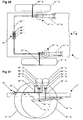
- Figure 20
- shows a schematic top view of a portion of a vehicle chassis having an alternative wheel suspension according to the present invention; and
- Figure 21
- shows a side view of a pair of wheels in connection with the wheel suspension according to Figure 20.
- The pram chassis shown in figures 1 and 2 comprises a
frame 1 that in its turn comprises two longitudinalfirst rods 3 and two transversesecond rods 5, saidfirst rods 3 and saidsecond rods 5 being mutually connected in a suitable way, e.g. by means of welding, in order to provide arigid frame 1 that is able to handle the forces acting on theframe 1. - In the area of both ends of the
frame 1, seen in the longitudinal direction of theframe 1, anaxle 7 is provided, saidaxle 7 constituting an essential element of the wheel suspension according to the present invention. Theaxle 7 comprises anintermediate portion 9 and two generally Z-shapedportions 10 that are provided at both ends of theintermediate portion 9. Upon the free ends of the Z-shapedportions 10wheels axle 7 and thewheels - In figure 3 the Z-shaped
portion 10 is shown in detail. Aninner portion 12 of the Z-shapedportion 10 is rotatably received in abearing 13 that is supported by theframe 1. Thebearing 13 is preferably a so-called teflon bearing. The Z-shapedportion 10 also includes anintermediate portion 14 that projects from theinner portion 12, and anouter portion 15 that projects from the end of theintermediate portion 14 that faces away from theinner portion 12. Since theportion 10 generally is Z-shaped theintermediate portion 14 has a longitudinal direction that extends transverse to the longitudinal direction of theinner portion 12 and theouter portion 15 has a longitudinal direction that extends transverse to the longitudinal direction of theintermediate portion 14. Preferably, the longitudinal direction of theintermediate portion 14 is perpendicular to the longitudinal direction of theinner portion 12 and theouter portion 15 and the longitudinal directions of theinner portion 12 and theouter portion 15 are parallel. On theouter portion 15 a wheel (not shown in figure 3) is mounted, said wheel being rotatable relative to theouter portion 15. Theintermediate portion 14 has an extension in the longitudinal direction/travelling direction of the pram, said direction being illustrated by thedouble arrow 2 in figures 1 and 2. - One end of the
intermediate portion 9 is received at the free end of theinner portion 12, said connection between the Z-shapedportion 10 and theintermediate portion 9 should be rigid. Said connection is preferably achieved by drilling and welding. Theintermediate portion 9 is preferably manufactured from spring steel while the Z-shapedportion 10 preferably is manufactured from a stiffer steel quality. The importance of this will be explained below in connection with the description of the function of the wheel suspension. - As is evident from figures 1 and 3 an iron flat 16 is rigidly attached at the middle of each
intermediate portion 9. As is evident from figure 1 afirst spring 17 is mounted between the iron flat 16 and the adherent transversesecond rod 5. The function of the arrangement with the iron flat 16 and thefirst springs 17 will be described below. The first springs 17 constitute tension springs. - In the alternative embodiment of the present invention shown in figures 4 and 5 the wheel suspension is applied to a sulky. In connection therewith only the areas of the ends of the frame 1' is shown, said ends receiving the two
axles 7 that have a principally similar design as theaxles 7 according to figures 1-2. For this reason the axles of figures 4-5 have been given thereference numerals 7 and the wheels have been given thereference numerals - When viewing figures 4 and 5 it is realised that the frame 1' has a different design compared to the
frame 1. Thus the frame 1' comprises two sub-frames that are only partly shown in figures 4 and 5. In areas where they cross each other the sub frames 1' are in a conventional way hingedly connected to each other. - In figures 6a-6c the "behaviour" of the
wheels groove 18 in a pavement, saidwheels axle 7 in accordance with the invention. In order to distinguish the Z-shaped portions at respective end of theaxle 7 said portions have been given the additional designation "a" and "b" respectively in conformity with the designation of thewheels axle 7. - In the illustrated example the
groove 18 has such a width that thewheel 11a that travels at the front in the longitudinal direction/travelling direction of the pram remains hanging in the air due to the structural design of the wheel suspension according to the present invention. The longitudinal direction/travelling direction is illustrated by thearrow 2 in figures 6a-6c. When the front travellingwheel 11a looses its contact with the ground it will move downwards on one hand due to the weight of thewheel 11a and on the other hand due to the load that the frame 1' applies to theintermediate portion 9 of theaxle 7. The distance that thecentre axle 15a of thefront wheel 11a moves downwards in relation to thecentre axle 15b of therear wheel 15b is designated by d in figure 6a. When thecentre axle 15a of thefront wheel 11a strives to move downwards due to the applied forces described above, said downwards movement will be counteracted by thefirst tension spring 17, see figure 6a, that strives to return the iron flat 16 to its initial position. When the iron flat 16 is turned a certain predetermined angle from its initial position thetension spring 17 will become elongated a certain distance. If further turning of the iron flat 16 occurs beyond said predetermined angle thetension spring 17 will be elongated more compared to the turning from the initial position. The fact that theintermediate portion 9 is designed as a torque axle brings about an inherent spring suspension that gives the pram chassis an evened travel across unevennesses in the ground. This is especially important when an axle is subjected to a load and both wheels are pushed upwards simultaneously. An extremely important feature of the wheel suspension according to the present invention is the fact that theintermediate portion 9 of theaxle 7 only moves downwards about half the distance that thecentre axle 15a moves downwards, this being evident from figure 6a, where the distance that theintermediate portion 9 moves downwards is designated by d/2. - In figure 6b it is shown how the pair of
wheels groove 18 andrespective wheels groove 18. In figure 6b it is also illustrated how a conventional pair of wheels behaves when passing thegroove 18, the wheel in this case being dotted along its entire circumference. The conventional pair of wheels, said pair being symbolised by the dotted wheel, will descend into thegroove 18 to an essentially larger degree than the pair ofwheels groove 18 has been designated by "e" in figure 6b. - In figure 6c the behaviour of the pair of
wheels groove 18, this in principle being mirror-inverted compared to figure 6a. - In figure 6a-6c it is illustrated the case when the
front wheel 11a runs down in agroove 18 or the like. However, the wheel suspension according to the present invention functions equal well if thefront wheel 11a runs over an elevation in the ground. In such a case thefront wheel 11a will be raised relative to therear wheel 11b. However, the wheel suspension will function in principally the same way as regards the evening effect upon unevennesses in the ground. - For security reasons the structure shown in figure 6 should be equipped with some kind of deflection limiter to prevent the wheel suspension from tilting to one side in an uncontrolled manner if a large load is applied to said side. In such a case several different solutions are feasible, for example the type of deflection limiter that is shown in the embodiments described below. It is also feasible that the deflection limiter is integral with the spring in such a way that the spring is allowed to be extended/compressed only a certain distance before it reaches a stop.
- The wheel suspension according to the present invention that is schematically shown in figures 7-9 is applied to a set of wheels comprising a pair of wheels of a so-called umbrella stroller. In this case an
axle 7" is rotatably attached to arear sub-frame 1"a of the umbrella stroller, saidaxle 7" having a intermediatestraight portion 9". The umbrella stroller comprises for such sub-frames that are included in the frame of the umbrella stroller. Theaxle 7" also comprises two Z-shapedportions 10"a and 10"b respectively, that are arranged at respective ends of theintermediate portion 9". Each of the Z-shapedportions 10" comprises anouter portion 15"a and 15"b respectively that are parallel to theintermediate portion 9". On theouter portions 15"a and 15"b wheels 11"a and 11"b are mounted, saidouter portions 15"a and 15"b constituting centre axles for thewheels 11"a and 11"b. As is most evident from figures 7 and 8 afirst compression spring 17", preferably a progressive compression spring, is mounted between theaxle 7" and a fixed bracket on thesub-frame 1"a. Thefirst compression spring 17" has principally the same function as thefirst tension spring 17 in the embodiments described above, however with the difference that the lower end of thecompression spring 17" is not attached to theaxle 7". This means that when thefront wheel 11"a enters a curb or the like the portion of theaxle 7" that is located directly opposite thecompression spring 17", i.e. the rear portion of theaxle 7", will move away from thecompression spring 17" that thus is inactive. This structural design brings about that the set of wheels according to figures 7-9 easily rolls over an obstacle. However, to guarantee that the wheel suspension according to figures 7-9 not is subjected to an uncontrolled rotation, when for instance the front wheel passes over a large upright obstacle, the embodiment according to figures 7-9 is equipped with astop 19". Otherwise the embodiment according to figures 7-9 functions in principally the corresponding way as the embodiments according to figures 1-2 and figures 4-5 respectively, the most evident structural difference being that theintermediate portion 9" is essentially shorter in the embodiment according to figures 7-9 than in the embodiments according to figures 1-2 and figures 4-5 respectively. - In figures 10-12 and figures 13a-13c a further alternative embodiment is shown where three
wheels 11"'a, 11"'b, 11"'c define a set of wheels. In this case the Ω-axle 7"' that carries thewheels 11"'a, 11"'b, 11"'c constitutes in principle two assembled Z-axles and the centrally locatedcentre axle 15"'b of theaxle 7"' is displaced in the longitudinal direction/travellingdirection 2"' of the vehicle relative to the twoother centre axles 15"'a and 15"'c. Theaxle 7"' is pivotally suspended in asub-frame 1"'a by means ofpins 8"'. Further, twostops 19"'b and 19"'c are attached to thesub-frame 1"'a in order to limit the pivoting of theaxle 7"'. In figures 13a-13c it is schematically illustrated how the set of wheels in the embodiment according to figures 10-12 behaves when it passes anupright obstacle 27. In connection therewith thewheel 11"'b travelling first in the longitudinal direction/travellingdirection 2 of the vehicle will move upwards as it looses its contact with the ground, see figure 13a. In connection therewith thestop 19"'b guarantees that there is no uncontrolled rotation of thefront wheel 11"'b relative to therear wheels 11"'a and 11"'c. Thestop 19"'b functions in such a way that theintermediate portion 14"'a will abut saidstop 19"'b when the upwards movement of thefront wheel 11"'b has reached a predetermined value. In connection therewith uncontrolled rotation of thefront wheel 11"'b is prevented. Empirically it has shown that the required force in the travelling direction of the vehicle to transfer the wheel suspension from the position according to figure 13a to the position according to figure 13b is only half the force that is required in connection with a conventional wheel suspension, i.e. when the wheels simultaneously are elevated on top of theupright obstacle 27. This has been illustrated in figure 13a by the designation F/2 of the required force. - In figure 13b it is shown the position when all three
wheels 11"'a, 11"'b and 11"'c are located on top of theupright obstacle 27. In figure 13c thefront wheel 11"'b has left theupright obstacle 27 and remained hanging in the air before it has reached down to the level of the ground that surrounds theupright obstacle 27. If the difference in height is sufficient large theintermediate portion 14"'b will abut thestop 19"'c. - A significant feature of the embodiment according to figures 10-12 is that the set of wheels in principle not being subjected to any lateral forces that may bring the set of wheels and hence also the
sub-frame 1"'a to rotate around a vertical axis. The reason therefore is that an unevenness either is hit by the centrally locatedwheel 11"'b or simultaneously by theouter wheels 11"'a and 11"'c. This means that there is in principle no torque action in connection with the embodiment according to figures 10-12. - In figures 14-16 a further alternative embodiment is shown, this being a variant of the embodiment according to figures 10-12. What principally differs between the embodiment according to figures 14-16 and the embodiment according to figures 10-12 is that a further centrally located wheel is provided. Since these both embodiments are so alike the same reference numerals have been used with the exception that in the embodiment according to figures 14-16 the centrally located wheels have been given the
reference numerals 11"'b1 and 11"'b2 respectively. As regards the function of the embodiment according to figures 14-16 this embodiment possesses the quality that thesub-frame 1"'a is extremely easily rotatable around a vertical axis, especially when the set of wheels is subjected to a heavy load. - In order to use the properties of the different embodiments of the present invention in an optimal way it might be suitable that in connection with a so-called umbrella stroller, walker or consignment cage the both rear sets of wheels are designed in accordance with the embodiment shown in figures 7-9 while the front sets of wheels are designed in accordance with the embodiment shown in figures 10-12 or figures 14-16.
- In figures 17-19 a further embodiment of a wheel suspension according to the present invention is shown. This embodiment in principle being a doubling of the embodiment according to figures 7-9. For that reason similar but modified reference numerals have been used in figures 17-19 as in figures 7-9. As regards the function of the wheel suspension according to figures 17-19 it corresponds in principle to the function of the embodiment according to figures 7-9.
- As regards the use of the wheel suspension according to the present invention in connection with prams the distance between the
centre axles axle 7; 7". This means that the conventional spring suspension that prams are equipped with may be deleted. - In figures 20 and 21 a further alternative embodiment of the present invention is shown, said embodiment constituting a hydraulic variant. The wheel suspension according to figures 20 and 21 comprises two pivoting
arms 14""a and 14""b that at one end are pivotally connected to aframe 1"" while the other end of the pivotingarms 14""a and 14""b respectively carries acentre axle 15""a and 15""b of awheel 11""a and 11""b respectively. An intermediate portion of the pivotingarms 14""a and 14""b is viarods 20""a and 20""b connected tohydropneumatic units 21""a and 21""b that are mounted on theframe 1"". Thehydropneumatic units 21""a and 21""b are via apipe 22"" mutually connected with each other. The unit that comprises the pivotingarms 14""a, 14""b, thewheels 15""a, 15""b, thehydropneumatic units 21""a, 21""b and thepipe 22"" is called a set of wheels. In eachhydropneumatic unit 21""a, 21""b a membrane 25""a and 25""b respectively is provided, saidmembrane 25""a, 25""b dividing each hydropneumatic unit in two compartments. Thecompartment 23""a, 23""b above themembrane 25""a, 25""b constitutes a pressure reservoir and is filled with compressible gas while the compartment below themembrane 25""a, 25""b constitutes atubular unit 26""a, 26""b that is filled with hydraulic oil. Said hydraulic oil flows in thepipe 22"" since it is connected to the respectivetubular unit 26""a, 26""b of thehydropneumatic units 21""a, 21""b. - On the ends of the
rods 20""a and 20""b that face away from the pivotingarms 14""a and 14""b sealing means 24""a and 24""b respectively are attached, said sealing means 24""a and 24""b being displacable in thetubular unit 26""a and 26""b respectively of thehydropneumatic units 21""a and 21""b. Thepipe 22 is connected to thehydropneumatic units 21""a and 21""b in such a way that it is in connection with the hydraulic oil enclosed in thetubular units 26""a and 26""b. - In the
pipe 22"" abalancing cylinder 28"" is also provided, saidcylinder 28"" comprising apiston 29"" and two on both sides of thepiston 29"" arrangedprogressive springs 30"". Thesesprings 30"" contribute in keeping the vehicle in a horizontal equilibrium position (initial position) and thesprings 30"" functions in a principally corresponding way as for instance thespring 17 and the iron flat 16 in figures 1-2 and 4-6. - If for instance the
front wheel 11""a moves upwards therod 20""a, including the sealing means 24""a, will also move upwards thereby increasing the pressure in thetubular unit 26""a and compressing the gas above themembrane 25""a. In connection therewith the hydraulic oil that is located below themembrane 25""a will flow, via thepipe 22"", towards the balancingcylinder 28"" and an increased pressure is propagating to thetubular unit 26""b and therod 20""b moves downwards together with thecentre axle 15""b. The centre axles 15""a and 15""b thus moves away from each other in vertical direction when onewheel 11""a enters a stone or the like. - A principally important feature of the wheel suspension according to the present invention is that when passing unevennesses the wheels of a set are not simultaneously subjected to impulsive forces but in a timely extended process.
- To a sum up it may be noticed that an important difference between the wheel suspension according to the present invention and a bogie is that the wheels of a wheel suspension according to the present invention are not located in the same plane and that the wheels overlap each other seen in the direction of the wheel axles. Regarding a bogie the wheels are located in the same plane and consequently it is not possible that they overlap each other seen in the direction of the wheel axles.
- Although the invention primarily has been described above in connection with prams the invention must in no way be regarded as restricted to prams. The embodiment described in figures 20-21 is primarily intended for the car industry.
- In connection with the description above of figure 3 it is stated that the
intermediate portion 9 preferably is manufactured from spring steel while the Z-shapedportion 10 preferably is manufactured from a stiffer steel quality. However, within the scope of the invention it is feasible that theaxle 7; 7"; 7"' is manufactured from other materials. In exemplifying and non-restricting purposes plastic materials may be mentioned. Thereby, different parts of the axle may in a corresponding way be given different properties, e.g. regarding torque capacity.
Claims (9)
- Wheel suspension for vehicles comprising centre axles (15a, 15b; 15"a, 15"b; 15"a1, 15"b1, 15"a2, 15"b2; 15"'a, 15"'b; 15""a, 15""b) for wheels (11a, 11b; 11'a, 11'b; 11"a, 11"b; 11"a1, 11"b1, 11"a2, 11"b2; 11'"a, 11"'b, 11"'c; 11"'a, 11"'b1, 11"'b2, 11"'c; 11""a, 11""b) in a set of wheels, said centre axles (15a, 15b; 15"a, 15"b; 15"a1, 15"b1, 15"a2, 15"b2; 15"'a, 15"'b; 15""a, 15""b) being connected to elements (14, 14a, 14b; 14"'a, 14"'b; 14""a, 14""b) that extend in the travelling direction of the vehicle, that these elements (14, 14a, 14b; 14"'a, 14"'b; 14""a, 14""b) are hingedly/pivotally connected to a frame (1; 1'; 1"a; 1"'a; 1"") of the vehicle, that the centre axles (15a, 15b; 15"a, 15"b; 15"a1, 15"b1, 15"a2, 15"b2; 15"'a, 15"'b; 15""a, 15""b) of at least a pair of appertaining wheels (11a, 11b; 11'a, 11'b; 11"a, 11"b; 11"a1, 11"b1, 11"a2, 11"b2; 11"'a, 11"'b, 11'"c; 11"'a, 11"'b1/11"'b2, 11"'c; 11""a, 11""b) are located at a certain distance from each other in the longitudinal direction/travelling direction (2; 2"'; 2"') of the vehicle, that said pair of adjacent wheels (11a, 11b; 11'a, 11'b; 11"a, 11"b; 11"a1, 11"b1, 11"a2, 11"b2; 11"'a, 11"'b, 11"'c; 11"'a, 11"'b1/11"'b2, 11"'c; 11""a, 11""b) partially overlap each other seen in the longitudinal direction of the centre axles (15a, 15b; 15"a, 15"b; 15"a1, 15"b1, 15"a2, 15"b2; 15"'a, 15"'b/15"'b, 15"'c; 15""a, 15""b), and that the elements (14, 14a, 14b; 14'"a, 14"'b; 14""a, 14""b) that extend in the travelling direction of the vehicle are related to means (17; 17"; 17"'; 19"'; 21""a, Z1""b) to restrict the movement of the elements (14, 14a, 14b; 14"'a, 14"'b; 14""a, 14""b) when said elements (14, 14a, 14b; 14"'a, 14"'b; 14""a, 14""b) perform a movement upwards, and that the elements (14, 14a, 14b; 14"'a, 14"'b; 14""a, 14""b) that extend in the travelling direction of the vehicle are related to means (17; 17"; 17"'; 19"'; 21""a, 21""b) to restrict the movement of the elements (14, 14a, 14b; 14"'a, 14"'b; 14""a, 14""b) when said elements (14, 14a, 14b; 14"'a 14"'b; 14""a, 14""b) perform a movement downwards, characterized in that said restriction means (17; 17"; 17"'; 19"'; 21""a, 21""b) are non-active when said elements (14, 14a, 14b; 14"'a, 14"'b; 14""a, 14""b) are in an initial position.
- Wheel suspension according to claim 1,
characterized in that the centre axles (15a, 15b; 15"a, 15"b) are included in a through-going axle (7; 7") that has an intermediate portion (9: 9") constituting a torque axle. - Wheel suspension according to claim 1 or 2,
characterized in that each centre axle (15a, 15b; 15"a, 15"b; 15"'a, 15"'b) is included in a Z-shaped portion (10; 10"a, 10"b) that is included in a through-going axle (7; 7"; 7"'). - Wheel suspension according to any of the previous claims,
characterized in that the means applying a counter-acting force to the wheels (11a, 11b; 11'a, 11'b; 11"a; 11"'b1, 11"'b2) constitutes a tension spring/compression spring (17; 17"; 17"'). - Wheel suspension according to any of the previous claims,
characterized in that the compression spring (17"; 17"') is progressive. - Wheel suspension according to claim 1,
characterized in that the means applying a counter-acting force to the wheel/wheels (11"a1, 11"a2; 11"'b) constitutes a stop (19"; 19"'). - Wheel suspension according to claim 1,
characterized in that the means applying a counter-acting force to the wheel/wheels (11"'a, 11""b) constitutes pressure medium in a closed system. - Wheel suspension according to claim 7,
characterized in that the closed system comprises two hydropneumatic units (21""a, 21""b) that are mutually connected by means of a pipe (22""), and that the elements (14""a, 19""b) extending in the travelling direction of the vehicle are connected to the hydropneumatic units (21""a, 21""b) and balanced by the pressure in the hydropneumatic units (21""a, 21""b). - Wheel suspension according to claim 8,
characterized in that each hydropneumatic unit (21""a, 21""b) comprises a pressure reservoir (23""a, 23""b) that holds a compressive gas, and a tubular unit (26""a, 26""b) that holds hydraulic oil, and that the pressure reservoir (23""a, 23""b) and the tubular unit (26""a, 26""b) are divided by a membrane (25""a, 25""b).
Applications Claiming Priority (3)
| Application Number | Priority Date | Filing Date | Title |
|---|---|---|---|
| SE0102878 | 2001-08-30 | ||
| SE0102878A SE0102878L (en) | 2001-08-30 | 2001-08-30 | Wheel suspension |
| PCT/SE2002/001537 WO2003018335A1 (en) | 2001-08-30 | 2002-08-29 | Wheel suspension |
Publications (2)
| Publication Number | Publication Date |
|---|---|
| EP1420967A1 EP1420967A1 (en) | 2004-05-26 |
| EP1420967B1 true EP1420967B1 (en) | 2006-08-09 |
Family
ID=20285169
Family Applications (1)
| Application Number | Title | Priority Date | Filing Date |
|---|---|---|---|
| EP02765732A Expired - Lifetime EP1420967B1 (en) | 2001-08-30 | 2002-08-29 | Wheel suspension |
Country Status (9)
| Country | Link |
|---|---|
| US (1) | US7249775B2 (en) |
| EP (1) | EP1420967B1 (en) |
| CN (1) | CN100515810C (en) |
| AT (1) | ATE335626T1 (en) |
| CA (1) | CA2458004C (en) |
| DE (1) | DE60213824T2 (en) |
| ES (1) | ES2269759T3 (en) |
| SE (1) | SE0102878L (en) |
| WO (1) | WO2003018335A1 (en) |
Families Citing this family (10)
| Publication number | Priority date | Publication date | Assignee | Title |
|---|---|---|---|---|
| SE0600335L (en) * | 2006-02-15 | 2007-01-16 | Stefan Kindberg | Wheel suspension |
| EP2357125A1 (en) * | 2010-02-17 | 2011-08-17 | Zouce AB | Vehicle having a level compensation system |
| US8702108B2 (en) | 2010-02-23 | 2014-04-22 | Zoomability Ab | Vehicle having a level compensation system |
| WO2012106756A1 (en) * | 2011-02-07 | 2012-08-16 | Mobility 2000 (Australia) Limited | Step-climbing attachment for a wheeled chair |
| CN205417852U (en) * | 2015-07-27 | 2016-08-03 | 张福贵 | Cat ladder hinders solar vehicle more |
| SE541097C2 (en) * | 2015-08-12 | 2019-04-02 | Rindus Ind Ab | Roll container and load carrying base for a roll container |
| SE541096C2 (en) * | 2015-08-12 | 2019-04-02 | Rindus Ind Ab | Roll container and load carrying base for a roll container |
| US11406890B1 (en) | 2017-08-25 | 2022-08-09 | David Jackson | Skateboard assembly |
| CN109911056A (en) * | 2019-01-28 | 2019-06-21 | 中山小神童创新科技有限公司 | A vehicle with a horizontal compensation system |
| DE102020119267A1 (en) * | 2020-07-21 | 2022-01-27 | Veronika Keller | Running gear for a push car and push car |
Family Cites Families (7)
| Publication number | Priority date | Publication date | Assignee | Title |
|---|---|---|---|---|
| US1149153A (en) * | 1913-10-14 | 1915-08-03 | Edward G Schleicher | Running-gear for vehicles. |
| GB573764A (en) * | 1943-03-17 | 1945-12-05 | Arthur Bloch | Improvements in hand propelled vehicles such as baby carriages |
| US2740623A (en) * | 1952-01-23 | 1956-04-03 | American Steel Foundries | Axle assembly |
| US4360212A (en) * | 1980-10-22 | 1982-11-23 | Gilbert Scigalski | Offset vehicle axle |
| DE3346660A1 (en) * | 1983-12-23 | 1985-07-18 | Boge Gmbh, 5208 Eitorf | HYDROPNEUMATIC SUSPENSION WITH LEVEL CONTROL FOR VEHICLES |
| CN2335812Y (en) * | 1998-01-08 | 1999-09-01 | 梁进 | Adjustable axle |
| AU8037800A (en) * | 1999-09-01 | 2001-03-26 | Dallas Smith Corporation | Staggered independent suspension |
-
2001
- 2001-08-30 SE SE0102878A patent/SE0102878L/en not_active Application Discontinuation
-
2002
- 2002-08-29 US US10/487,454 patent/US7249775B2/en not_active Expired - Lifetime
- 2002-08-29 ES ES02765732T patent/ES2269759T3/en not_active Expired - Lifetime
- 2002-08-29 WO PCT/SE2002/001537 patent/WO2003018335A1/en not_active Ceased
- 2002-08-29 CN CNB028168054A patent/CN100515810C/en not_active Expired - Fee Related
- 2002-08-29 AT AT02765732T patent/ATE335626T1/en not_active IP Right Cessation
- 2002-08-29 EP EP02765732A patent/EP1420967B1/en not_active Expired - Lifetime
- 2002-08-29 CA CA2458004A patent/CA2458004C/en not_active Expired - Fee Related
- 2002-08-29 DE DE60213824T patent/DE60213824T2/en not_active Expired - Lifetime
Also Published As
| Publication number | Publication date |
|---|---|
| ATE335626T1 (en) | 2006-09-15 |
| US20040232643A1 (en) | 2004-11-25 |
| SE0102878D0 (en) | 2001-08-30 |
| CN100515810C (en) | 2009-07-22 |
| WO2003018335A1 (en) | 2003-03-06 |
| CN1549777A (en) | 2004-11-24 |
| EP1420967A1 (en) | 2004-05-26 |
| ES2269759T3 (en) | 2007-04-01 |
| US7249775B2 (en) | 2007-07-31 |
| CA2458004A1 (en) | 2003-03-06 |
| CA2458004C (en) | 2011-11-01 |
| DE60213824D1 (en) | 2006-09-21 |
| DE60213824T2 (en) | 2007-03-01 |
| SE0102878L (en) | 2003-03-01 |
Similar Documents
| Publication | Publication Date | Title |
|---|---|---|
| US9381785B2 (en) | Tilting vehicle and a method of tilting a vehicle with rear wheel supports having hydraulic cylinders communicating through a pump | |
| US9381940B2 (en) | System and method for vehicle chassis control | |
| KR102511604B1 (en) | car front suspension | |
| US5820156A (en) | Vehicle suspension system | |
| US5437467A (en) | Stabilization device for vehicle | |
| EP3374254B1 (en) | Motor vehicle | |
| EP3666631A1 (en) | Forecarriage of tilting motor vehicle and motor vehicle thereof | |
| TWI717532B (en) | Tilting forecarriage of a motor vehicle and a related motor vehicle | |
| CN105829201A (en) | Rolling mechanism for multi-wheeled rolling vehicles | |
| US7249775B2 (en) | Wheel suspension | |
| CN107662665A (en) | Wheel base-variable multi-wheel type mobile platform | |
| WO1999061303A1 (en) | Tricycle with hydropneumatic independent rear suspension | |
| US5088570A (en) | Steerable rear dual axle system for large trucks | |
| US3439927A (en) | Suspension mechanism for vehicle wheels | |
| US6550797B2 (en) | Zero roll suspension system | |
| EP3501864B1 (en) | "afw-4" vehicle suspension | |
| US5108127A (en) | Vehicle suspension system | |
| US20010035623A1 (en) | Zero roll suspension system | |
| US4119170A (en) | Interacting steering-suspension system for a wheeled vehicle and the like | |
| HK1072227A (en) | Wheel suspension | |
| EP1206360B1 (en) | Vehicle with stability arrangement for moving structural components | |
| CZ2009269A3 (en) | Inclinable chassis | |
| JP2004315235A (en) | Yard cart with swivel seat |
Legal Events
| Date | Code | Title | Description |
|---|---|---|---|
| PUAI | Public reference made under article 153(3) epc to a published international application that has entered the european phase |
Free format text: ORIGINAL CODE: 0009012 |
|
| 17P | Request for examination filed |
Effective date: 20040210 |
|
| AK | Designated contracting states |
Kind code of ref document: A1 Designated state(s): AT BE BG CH CY CZ DE DK EE ES FI FR GB GR IE IT LI LU MC NL PT SE SK TR |
|
| AX | Request for extension of the european patent |
Extension state: AL LT LV MK RO SI |
|
| 17Q | First examination report despatched |
Effective date: 20041124 |
|
| GRAP | Despatch of communication of intention to grant a patent |
Free format text: ORIGINAL CODE: EPIDOSNIGR1 |
|
| RAP1 | Party data changed (applicant data changed or rights of an application transferred) |
Owner name: ROSENQUIST, JOHAN |
|
| RIN1 | Information on inventor provided before grant (corrected) |
Inventor name: ROSENQUIST, JOHAN |
|
| GRAS | Grant fee paid |
Free format text: ORIGINAL CODE: EPIDOSNIGR3 |
|
| GRAA | (expected) grant |
Free format text: ORIGINAL CODE: 0009210 |
|
| AK | Designated contracting states |
Kind code of ref document: B1 Designated state(s): AT BE BG CH CY CZ DE DK EE ES FI FR GB GR IE IT LI LU MC NL PT SE SK TR |
|
| PG25 | Lapsed in a contracting state [announced via postgrant information from national office to epo] |
Ref country code: CH Free format text: LAPSE BECAUSE OF FAILURE TO SUBMIT A TRANSLATION OF THE DESCRIPTION OR TO PAY THE FEE WITHIN THE PRESCRIBED TIME-LIMIT Effective date: 20060809 Ref country code: SK Free format text: LAPSE BECAUSE OF FAILURE TO SUBMIT A TRANSLATION OF THE DESCRIPTION OR TO PAY THE FEE WITHIN THE PRESCRIBED TIME-LIMIT Effective date: 20060809 Ref country code: LI Free format text: LAPSE BECAUSE OF FAILURE TO SUBMIT A TRANSLATION OF THE DESCRIPTION OR TO PAY THE FEE WITHIN THE PRESCRIBED TIME-LIMIT Effective date: 20060809 Ref country code: AT Free format text: LAPSE BECAUSE OF FAILURE TO SUBMIT A TRANSLATION OF THE DESCRIPTION OR TO PAY THE FEE WITHIN THE PRESCRIBED TIME-LIMIT Effective date: 20060809 Ref country code: CZ Free format text: LAPSE BECAUSE OF FAILURE TO SUBMIT A TRANSLATION OF THE DESCRIPTION OR TO PAY THE FEE WITHIN THE PRESCRIBED TIME-LIMIT Effective date: 20060809 Ref country code: FI Free format text: LAPSE BECAUSE OF FAILURE TO SUBMIT A TRANSLATION OF THE DESCRIPTION OR TO PAY THE FEE WITHIN THE PRESCRIBED TIME-LIMIT Effective date: 20060809 Ref country code: BE Free format text: LAPSE BECAUSE OF FAILURE TO SUBMIT A TRANSLATION OF THE DESCRIPTION OR TO PAY THE FEE WITHIN THE PRESCRIBED TIME-LIMIT Effective date: 20060809 |
|
| REG | Reference to a national code |
Ref country code: GB Ref legal event code: FG4D |
|
| PG25 | Lapsed in a contracting state [announced via postgrant information from national office to epo] |
Ref country code: IE Free format text: LAPSE BECAUSE OF NON-PAYMENT OF DUE FEES Effective date: 20060829 |
|
| PG25 | Lapsed in a contracting state [announced via postgrant information from national office to epo] |
Ref country code: MC Free format text: LAPSE BECAUSE OF NON-PAYMENT OF DUE FEES Effective date: 20060831 |
|
| REG | Reference to a national code |
Ref country code: CH Ref legal event code: EP |
|
| REG | Reference to a national code |
Ref country code: IE Ref legal event code: FG4D |
|
| REF | Corresponds to: |
Ref document number: 60213824 Country of ref document: DE Date of ref document: 20060921 Kind code of ref document: P |
|
| PG25 | Lapsed in a contracting state [announced via postgrant information from national office to epo] |
Ref country code: DK Free format text: LAPSE BECAUSE OF FAILURE TO SUBMIT A TRANSLATION OF THE DESCRIPTION OR TO PAY THE FEE WITHIN THE PRESCRIBED TIME-LIMIT Effective date: 20061109 Ref country code: BG Free format text: LAPSE BECAUSE OF FAILURE TO SUBMIT A TRANSLATION OF THE DESCRIPTION OR TO PAY THE FEE WITHIN THE PRESCRIBED TIME-LIMIT Effective date: 20061109 |
|
| REG | Reference to a national code |
Ref country code: SE Ref legal event code: TRGR |
|
| PG25 | Lapsed in a contracting state [announced via postgrant information from national office to epo] |
Ref country code: PT Free format text: LAPSE BECAUSE OF FAILURE TO SUBMIT A TRANSLATION OF THE DESCRIPTION OR TO PAY THE FEE WITHIN THE PRESCRIBED TIME-LIMIT Effective date: 20070109 |
|
| REG | Reference to a national code |
Ref country code: CH Ref legal event code: PL |
|
| ET | Fr: translation filed | ||
| REG | Reference to a national code |
Ref country code: ES Ref legal event code: FG2A Ref document number: 2269759 Country of ref document: ES Kind code of ref document: T3 |
|
| PLBE | No opposition filed within time limit |
Free format text: ORIGINAL CODE: 0009261 |
|
| STAA | Information on the status of an ep patent application or granted ep patent |
Free format text: STATUS: NO OPPOSITION FILED WITHIN TIME LIMIT |
|
| 26N | No opposition filed |
Effective date: 20070510 |
|
| PG25 | Lapsed in a contracting state [announced via postgrant information from national office to epo] |
Ref country code: GR Free format text: LAPSE BECAUSE OF FAILURE TO SUBMIT A TRANSLATION OF THE DESCRIPTION OR TO PAY THE FEE WITHIN THE PRESCRIBED TIME-LIMIT Effective date: 20061110 |
|
| PG25 | Lapsed in a contracting state [announced via postgrant information from national office to epo] |
Ref country code: EE Free format text: LAPSE BECAUSE OF FAILURE TO SUBMIT A TRANSLATION OF THE DESCRIPTION OR TO PAY THE FEE WITHIN THE PRESCRIBED TIME-LIMIT Effective date: 20060809 |
|
| PG25 | Lapsed in a contracting state [announced via postgrant information from national office to epo] |
Ref country code: TR Free format text: LAPSE BECAUSE OF FAILURE TO SUBMIT A TRANSLATION OF THE DESCRIPTION OR TO PAY THE FEE WITHIN THE PRESCRIBED TIME-LIMIT Effective date: 20060809 Ref country code: LU Free format text: LAPSE BECAUSE OF NON-PAYMENT OF DUE FEES Effective date: 20060829 |
|
| PG25 | Lapsed in a contracting state [announced via postgrant information from national office to epo] |
Ref country code: CY Free format text: LAPSE BECAUSE OF FAILURE TO SUBMIT A TRANSLATION OF THE DESCRIPTION OR TO PAY THE FEE WITHIN THE PRESCRIBED TIME-LIMIT Effective date: 20060809 |
|
| REG | Reference to a national code |
Ref country code: SE Ref legal event code: RPOT |
|
| REG | Reference to a national code |
Ref country code: GB Ref legal event code: 732E Free format text: REGISTERED BETWEEN 20100624 AND 20100630 |
|
| REG | Reference to a national code |
Ref country code: FR Ref legal event code: TP |
|
| REG | Reference to a national code |
Ref country code: NL Ref legal event code: SD Effective date: 20100831 |
|
| REG | Reference to a national code |
Ref country code: ES Ref legal event code: PC2A Owner name: TRIONIC SVERIGE AB Effective date: 20110208 |
|
| PGFP | Annual fee paid to national office [announced via postgrant information from national office to epo] |
Ref country code: NL Payment date: 20140820 Year of fee payment: 13 |
|
| PGFP | Annual fee paid to national office [announced via postgrant information from national office to epo] |
Ref country code: FR Payment date: 20140821 Year of fee payment: 13 Ref country code: ES Payment date: 20140826 Year of fee payment: 13 |
|
| PGFP | Annual fee paid to national office [announced via postgrant information from national office to epo] |
Ref country code: IT Payment date: 20140827 Year of fee payment: 13 |
|
| PG25 | Lapsed in a contracting state [announced via postgrant information from national office to epo] |
Ref country code: IT Free format text: LAPSE BECAUSE OF NON-PAYMENT OF DUE FEES Effective date: 20150829 |
|
| REG | Reference to a national code |
Ref country code: NL Ref legal event code: MM Effective date: 20150901 |
|
| REG | Reference to a national code |
Ref country code: FR Ref legal event code: ST Effective date: 20160429 |
|
| PG25 | Lapsed in a contracting state [announced via postgrant information from national office to epo] |
Ref country code: NL Free format text: LAPSE BECAUSE OF NON-PAYMENT OF DUE FEES Effective date: 20150901 |
|
| PG25 | Lapsed in a contracting state [announced via postgrant information from national office to epo] |
Ref country code: FR Free format text: LAPSE BECAUSE OF NON-PAYMENT OF DUE FEES Effective date: 20150831 |
|
| REG | Reference to a national code |
Ref country code: ES Ref legal event code: FD2A Effective date: 20160926 |
|
| PG25 | Lapsed in a contracting state [announced via postgrant information from national office to epo] |
Ref country code: ES Free format text: LAPSE BECAUSE OF NON-PAYMENT OF DUE FEES Effective date: 20150830 |
|
| PGFP | Annual fee paid to national office [announced via postgrant information from national office to epo] |
Ref country code: DE Payment date: 20180823 Year of fee payment: 17 |
|
| PGFP | Annual fee paid to national office [announced via postgrant information from national office to epo] |
Ref country code: GB Payment date: 20180822 Year of fee payment: 17 Ref country code: SE Payment date: 20180823 Year of fee payment: 17 |
|
| REG | Reference to a national code |
Ref country code: DE Ref legal event code: R119 Ref document number: 60213824 Country of ref document: DE |
|
| REG | Reference to a national code |
Ref country code: SE Ref legal event code: EUG |
|
| GBPC | Gb: european patent ceased through non-payment of renewal fee |
Effective date: 20190829 |
|
| PG25 | Lapsed in a contracting state [announced via postgrant information from national office to epo] |
Ref country code: SE Free format text: LAPSE BECAUSE OF NON-PAYMENT OF DUE FEES Effective date: 20190830 |
|
| PG25 | Lapsed in a contracting state [announced via postgrant information from national office to epo] |
Ref country code: DE Free format text: LAPSE BECAUSE OF NON-PAYMENT OF DUE FEES Effective date: 20200303 |
|
| PG25 | Lapsed in a contracting state [announced via postgrant information from national office to epo] |
Ref country code: GB Free format text: LAPSE BECAUSE OF NON-PAYMENT OF DUE FEES Effective date: 20190829 |