EP1420615A1 - Microwave oven equipped with toaster and method of controlling the same - Google Patents
Microwave oven equipped with toaster and method of controlling the same Download PDFInfo
- Publication number
- EP1420615A1 EP1420615A1 EP03253326A EP03253326A EP1420615A1 EP 1420615 A1 EP1420615 A1 EP 1420615A1 EP 03253326 A EP03253326 A EP 03253326A EP 03253326 A EP03253326 A EP 03253326A EP 1420615 A1 EP1420615 A1 EP 1420615A1
- Authority
- EP
- European Patent Office
- Prior art keywords
- heaters
- toaster
- microwave oven
- magnetron
- mgt
- Prior art date
- Legal status (The legal status is an assumption and is not a legal conclusion. Google has not performed a legal analysis and makes no representation as to the accuracy of the status listed.)
- Granted
Links
Images




Classifications
-
- F—MECHANICAL ENGINEERING; LIGHTING; HEATING; WEAPONS; BLASTING
- F24—HEATING; RANGES; VENTILATING
- F24C—DOMESTIC STOVES OR RANGES ; DETAILS OF DOMESTIC STOVES OR RANGES, OF GENERAL APPLICATION
- F24C7/00—Stoves or ranges heated by electric energy
- F24C7/02—Stoves or ranges heated by electric energy using microwaves
-
- H—ELECTRICITY
- H05—ELECTRIC TECHNIQUES NOT OTHERWISE PROVIDED FOR
- H05B—ELECTRIC HEATING; ELECTRIC LIGHT SOURCES NOT OTHERWISE PROVIDED FOR; CIRCUIT ARRANGEMENTS FOR ELECTRIC LIGHT SOURCES, IN GENERAL
- H05B6/00—Heating by electric, magnetic or electromagnetic fields
- H05B6/64—Heating using microwaves
- H05B6/80—Apparatus for specific applications
-
- A—HUMAN NECESSITIES
- A47—FURNITURE; DOMESTIC ARTICLES OR APPLIANCES; COFFEE MILLS; SPICE MILLS; SUCTION CLEANERS IN GENERAL
- A47J—KITCHEN EQUIPMENT; COFFEE MILLS; SPICE MILLS; APPARATUS FOR MAKING BEVERAGES
- A47J37/00—Baking; Roasting; Grilling; Frying
- A47J37/06—Roasters; Grills; Sandwich grills
- A47J37/08—Bread-toasters
-
- F—MECHANICAL ENGINEERING; LIGHTING; HEATING; WEAPONS; BLASTING
- F24—HEATING; RANGES; VENTILATING
- F24C—DOMESTIC STOVES OR RANGES ; DETAILS OF DOMESTIC STOVES OR RANGES, OF GENERAL APPLICATION
- F24C15/00—Details
- F24C15/18—Arrangement of compartments additional to cooking compartments, e.g. for warming or for storing utensils or fuel containers; Arrangement of additional heating or cooking apparatus, e.g. grills
-
- H—ELECTRICITY
- H05—ELECTRIC TECHNIQUES NOT OTHERWISE PROVIDED FOR
- H05B—ELECTRIC HEATING; ELECTRIC LIGHT SOURCES NOT OTHERWISE PROVIDED FOR; CIRCUIT ARRANGEMENTS FOR ELECTRIC LIGHT SOURCES, IN GENERAL
- H05B2206/00—Aspects relating to heating by electric, magnetic, or electromagnetic fields covered by group H05B6/00
- H05B2206/04—Heating using microwaves
- H05B2206/042—Microwave oven combined with a toaster or including a toaster
Definitions
- the present invention relates, in general, to a microwave oven equipped with a toaster and a method of controlling the same and, more particularly, to a microwave oven equipped with a toaster having a plurality of heaters and a method of controlling the same.
- a microwave oven is an apparatus that cooks foods using microwaves provided to a cooking cavity from a magnetron.
- the microwave oven equipped with the toaster is disclosed in detail in Korean Patent Unexamined Publication No. 2002-45200.
- the toaster that toasts bread is integrated in a body of the microwave oven, and an operation button that controls the operation of the toaster is disposed in a control panel in which various buttons controlling various operations of the microwave oven are disposed.
- the toaster is provided with two slot openings, which contain the bread to be toasted therein, in the body of the toaster formed in a rectangular shape. Further, the toaster is provided with heaters, which are electrically controlled and radiate heat to toast the bread contained in the two slot openings, at opposite sides of each of the two slot openings.
- the toaster is operated by a drive circuit that allows power to be supplied to the heaters of the toaster when the operation button of the toaster is pressed.
- the drive circuit allows the power supplied to the heaters to be cut off before the operation button of the toaster is pressed, while the drive circuit allows the power to be supplied to the heaters when the operation button of the toaster is pressed.
- the power is supplied to all of the heaters when the operation button of the toaster is pressed. Accordingly, the heaters are not individually operated. Therefore, the conventional microwave oven is problematic in that a portion of the power is supplied to a heater that is not used to toast the bread and the portion of the power is undesirably consumed.
- the toaster and the magnetron are independently controlled in the conventional microwave oven. Accordingly, when the operation button of the toaster is pressed, the toaster is operated regardless of a cooking operation being provided by the magnetron, so a consumption current is increased. Therefore, if the toaster is disposed in a wall mounted microwave oven having a limited consumption current, a circuit breaker in a home may be operated by a flow of an excessive consumption current, which can cause, for example, a power failure.
- An aim of the present invention is to provide a microwave oven equipped with a toaster and a method of controlling the same, where power is not undesirably consumed.
- Another aim of the present invention is to provide a microwave oven equipped with a toaster and a method of the controlling the same, where excessive consumption current is prevented.
- a microwave oven equipped with a toaster including a plurality of slot openings that contain bread therein, a plurality of heaters that radiate heat to the bread contained in the slot openings, a plurality of switching units that control a power supply to the heaters, a key input unit that receives key commands to selectively operate the switching units, and a control unit that controls corresponding switching units in response to the key commands.
- a microwave oven equipped with a toaster including a plurality of slot openings for the toaster, a plurality of heaters that are adjacently disposed to the slot openings and heat the slot openings, a plurality of input keys that allow the heaters to be operated, a plurality of switching units that switches an electric connection of a power supply to the heaters to selectively operate the heaters, and a control unit that controls the switching units in response to input signals of the input keys.
- a method of controlling a microwave oven equipped with a toaster including determining whether a key command that allows the toaster to be operated is inputted, determining whether a magnetron is in operation if the key command is inputted, delaying an operation of the toaster if the magnetron is in operation, and operating the toaster if the magnetron is not in operation.
- FIG. 1 is a perspective view of a microwave oven equipped with a toaster in accordance with an embodiment of the present invention.
- a toaster 20 that toasts bread is integrated in a body 10 of the microwave oven, and a key input unit 12 that receives key commands is disposed in a control panel 11 in which various buttons controlling various operations of the microwave oven are provided.
- the toaster 20 is provided with a first slot opening 21 and a second slot opening 22, which receive the bread to be toasted therein, the first and second slot openings 21 and 22 being provided in a body of the toaster 20 and formed in a rectangular shape. Further, the toaster 20 is provided with first, second and third heaters 23, 24 and 25, as shown in Figure 2, which are electrically controlled and radiate heat to toast the bread contained in the first slot opening 21 and the second slot opening 22, at opposite sides of each of the first slot opening 21 and the second slot opening 22.
- the key input unit 12 includes a first button 12a and a second button 12b as operation buttons of the toaster 20.
- the first button 12a is used to operate the first and second heaters 23 and 24 when the bread is contained in the first slot opening 21, and the second button 12b is used to operate the first, second and third heaters 23, 24 and 25 when the bread is contained in the first slot opening 21 and the second slot opening 22, respectively (see Figure 2).
- Figure 2 is a schematic sectional view of the toaster shown in Figure 1.
- the first slot opening 21 and the second slot opening 22 are provided in parallel.
- the first heater 23 is disposed at an outer side of the first slot opening 21.
- the second heater 24 is disposed between the first slot opening 21 and the second slot opening 22. Accordingly, the bread contained in the first slot opening 21 is toasted by receiving heat at opposite sides of the first slot opening 21 from the first and second heaters 23 and 24.
- the third heater 25 is disposed at an outer side of the second slot opening 22. Accordingly, the bread contained in the second slot opening 22 is toasted by receiving heat at opposite sides of the second slot opening 22 from the second and third heaters 24 and 25.
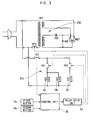
- FIG 3 is the drive circuit of the microwave oven equipped with the toaster having the first and second slot openings in accordance with the embodiment of the present invention.
- a toaster drive circuit 100 is included in a drive circuit of the microwave oven equipped with the toaster 20 having the first and second slot openings 21 and 22 in accordance with the embodiment of the present invention.
- the toaster drive circuit 100 is provided with a thermal cut-out TCO to prevent the overheating of the toaster.
- First terminals of a first relay switch RY1 and of a second relay switch RY2, which are connected to each other in parallel, are connected to one terminal of the thermal cut-out TCO.
- the first heater 23 and the second heater 24, which are connected to each other in parallel, are connected to a second terminal of the first relay switch RY1.
- the third heater 25 is connected to a second terminal of the second relay switch RY2.
- the first and second relay switches RY1 and RY2 are turned on or off by a relay drive unit 40, which is operated in response to control signals of a control unit 30 that controls an overall operation of the microwave oven.
- the control unit 30 drives the relay drive unit 40 by generating corresponding control signals in response to key commands that correspond to inputs of the first button 12a and the second button 12b.
- a high voltage unit control circuit 200 of the microwave oven that drives a magnetron MGT is included in the drive circuit of the microwave oven equipped with the toaster 20 having the first and second slot openings 21 and 22.
- the high voltage unit control circuit 200 of the microwave oven includes the magnetron MGT that oscillates at a high frequency, a high voltage transformer HVT that boosts a voltage of an input alternating current power supply and outputs the boosted voltage to the magnetron MGT, and a high voltage condenser HVC and a high voltage diode HVD that convert the boosted voltage outputted from the high voltage transformer HVT into a direct current DC of a high voltage.
- a third relay switch RY3 is connected between an external power supply and one terminal of the primary coil of the high voltage transformer HVT to operate the magnetron MGT.
- the high voltage unit control circuit 200 of the microwave oven that controls a high voltage unit and the toaster drive circuit 100 that drives the toaster 20 integrated in the microwave oven are connected to each other in parallel.
- Figures 4A and 4B are timing charts illustrating driving states of the first and second relay switches RY1 and RY2 when the first button 12a and the second button 12b shown in Figure 3 are pressed.
- the control unit 30 controls the relay drive unit 40 to turn on the first relay switch RY1 for a predetermined period T1 so that power is supplied to the first and second heaters 23 and 24, and allows the bread contained in the first slot opening 21 to be toasted for the predetermined period T1.
- the control unit 30 controls the relay drive unit 40 to turn on the first and second relay switches RY1 and RY2 so that the power is supplied to the first, second and third heaters 23, 24 and 25 for the predetermined period T1, and allows the bread contained in the first slot opening 21 and the second slot opening 22 to be toasted for the predetermined period T1.
- FIG. 5 is a control flowchart of a drive circuit of the microwave oven shown in Figure 3.
- control unit 30 determines whether the first button 12a is pressed to confirm whether a key command corresponding to an input of the first button 12a exists at operation 100.
- the control unit 30 determines whether the magnetron MGT is operating to confirm whether a cooking operation is performed at operation 101. If the magnetron MGT is operating at operation 101 so that the cooking operation is performed, the control unit 30 controls the first relay switch RY1 to be turned off at operation 102 and returns to operation 101. Since the first relay switch RY1 is turned off, a power supply to the first and second heaters 23 and 24 is cut off for a designated period T0 when the magnetron MGT is operating, so that the magnetron MGT and the toaster 20 are not simultaneously operated. If the magnetron MGT is not operating at operation 101, the control unit 30 controls the first relay switch RY1 to be turned on at operation 103. Since the first relay switch RY1 is turned on, the power is supplied to the first and second heaters 23 and 24, so that the toaster 20 is operated.
- the control unit 30 counts a turn-on period of the first relay switch RY1 at operation 104.
- the control unit 30 compares the counted turn-on period with the predetermined period T1 and determines whether the counted turn-on period is longer than the predetermined period T1 at operation 105. If the counted turn-on period is shorter than the predetermined period T1 at operation 105, the process returns to operation 103. If the counted turn-on period is equal to or longer than the predetermined period T1 at operation 105, the control unit 30 controls the first relay switch RY1 to be turned off so that the operation of the toaster 20 is stopped at operation 106.
- the control unit 30 determines whether the second button 12b is pressed to confirm whether a key command corresponding to an input of the second button 12b exists at operation 200.
- the control unit 30 determines whether the magnetron MGT is operating to confirm whether a cooking operation is performed at operation 201. If the magnetron MGT is operating at operation 201 so that the cooking operation is performed, the control unit 30 controls the first and second relay switches RY1 and RY2 to be turned off at operation 202 and returns to operation 201. Since the first and second relay switches RY1 and RY2 are turned off, the power supply to the first, second and third heaters 23, 24 and 25 are cut off for the designated period T0 when the magnetron MGT is operating, so that the magnetron MGT and the toaster 20 are not simultaneously operated.
- the control unit 30 controls the first and second relay switches RY1 and RY2 to be turned on at operation 203. Since the first and second relay switches RY1 and RY2 are turned on, the power is supplied to the first, second and third heater 23, 24 and 25, so that the toaster 20 is operated.
- the control unit 30 counts a turn-on period of the first and second relay switches RY1 and RY2 at operation 204.
- the control unit 30 compares the counted turn-on period with the predetermined period T1 and determines whether the counted turn-on period is longer than the predetermined period T1 at operation 205. If the counted turn-on period is shorter than the predetermined period T1 at operation 205, the process returns to operation 203. If the counted turn-on period is equal to or longer than the predetermined period T1 at operation 205, the control unit 30 controls the first and second relay switches RY1 and RY2 to be turned off so that the operation of the toaster 20 is stopped at operation 206.
- the magnetron and the heaters are prevented from being simultaneously operated, so that the consumption current is limited. Accordingly, a power failure resulting from an operation of an earth leakage breaker, which is operated by an excessive consumption current generated from simultaneous operations of the magnetron and the heaters, is prevented.
- the microwave oven equipped with the toaster and the method of controlling the same selectively operates the heaters provided in the toaster, thereby minimizing a power consumption caused by the undesired driving of the heaters.
- the magnetron is provided with a plurality of buttons that selectively operate the heaters provided in the toaster, thereby providing a convenience of a manipulation of the microwave oven to a user.
- the microwave oven equipped with the toaster and the method of controlling the same limits the consumption current of the microwave oven by preventing the toaster and the magnetron from being simultaneously operated, thus being applicable to, for example, wall mounted microwave ovens in which the consumption current is limited.
Landscapes
- Engineering & Computer Science (AREA)
- Chemical & Material Sciences (AREA)
- Combustion & Propulsion (AREA)
- Mechanical Engineering (AREA)
- General Engineering & Computer Science (AREA)
- Food Science & Technology (AREA)
- Physics & Mathematics (AREA)
- Electromagnetism (AREA)
- Electric Stoves And Ranges (AREA)
- Electric Ovens (AREA)
Abstract
Description
- The present invention relates, in general, to a microwave oven equipped with a toaster and a method of controlling the same and, more particularly, to a microwave oven equipped with a toaster having a plurality of heaters and a method of controlling the same.
- In general, a microwave oven is an apparatus that cooks foods using microwaves provided to a cooking cavity from a magnetron.
- Recently, a microwave oven in which a toaster that toasts bread is integrated has been developed.
- The microwave oven equipped with the toaster is disclosed in detail in Korean Patent Unexamined Publication No. 2002-45200.
- In the microwave oven equipped with the toaster, the toaster that toasts bread is integrated in a body of the microwave oven, and an operation button that controls the operation of the toaster is disposed in a control panel in which various buttons controlling various operations of the microwave oven are disposed.
- The toaster is provided with two slot openings, which contain the bread to be toasted therein, in the body of the toaster formed in a rectangular shape. Further, the toaster is provided with heaters, which are electrically controlled and radiate heat to toast the bread contained in the two slot openings, at opposite sides of each of the two slot openings.
- The toaster is operated by a drive circuit that allows power to be supplied to the heaters of the toaster when the operation button of the toaster is pressed. The drive circuit allows the power supplied to the heaters to be cut off before the operation button of the toaster is pressed, while the drive circuit allows the power to be supplied to the heaters when the operation button of the toaster is pressed.
- However, in the conventional microwave oven equipped with the toaster, the power is supplied to all of the heaters when the operation button of the toaster is pressed. Accordingly, the heaters are not individually operated. Therefore, the conventional microwave oven is problematic in that a portion of the power is supplied to a heater that is not used to toast the bread and the portion of the power is undesirably consumed.
- Further, the toaster and the magnetron are independently controlled in the conventional microwave oven. Accordingly, when the operation button of the toaster is pressed, the toaster is operated regardless of a cooking operation being provided by the magnetron, so a consumption current is increased. Therefore, if the toaster is disposed in a wall mounted microwave oven having a limited consumption current, a circuit breaker in a home may be operated by a flow of an excessive consumption current, which can cause, for example, a power failure.
- An aim of the present invention is to provide a microwave oven equipped with a toaster and a method of controlling the same, where power is not undesirably consumed.
- Another aim of the present invention is to provide a microwave oven equipped with a toaster and a method of the controlling the same, where excessive consumption current is prevented.
- Other aims and advantages of the invention will be set forth in part in the description which follows and, in part, will be obvious from the description, or may be learned by practice of the invention.
- According to the present invention there is provided an apparatus and method as set forth in the appended claims. Preferred features of the invention will be apparent from the dependent claims, and the description which follows.
- In one aspect of the present invention there is provided a microwave oven equipped with a toaster including a plurality of slot openings that contain bread therein, a plurality of heaters that radiate heat to the bread contained in the slot openings, a plurality of switching units that control a power supply to the heaters, a key input unit that receives key commands to selectively operate the switching units, and a control unit that controls corresponding switching units in response to the key commands.
- In a second aspect of the present invention there is provided a microwave oven equipped with a toaster including a plurality of slot openings for the toaster, a plurality of heaters that are adjacently disposed to the slot openings and heat the slot openings, a plurality of input keys that allow the heaters to be operated, a plurality of switching units that switches an electric connection of a power supply to the heaters to selectively operate the heaters, and a control unit that controls the switching units in response to input signals of the input keys.
- In a third aspect of the present invention there is provided a method of controlling a microwave oven equipped with a toaster including determining whether a key command that allows the toaster to be operated is inputted, determining whether a magnetron is in operation if the key command is inputted, delaying an operation of the toaster if the magnetron is in operation, and operating the toaster if the magnetron is not in operation.
- For a better understanding of the invention, and to show how embodiments of the same may be carried into effect, reference will now be made, by way of example, to the accompanying diagrammatic drawings in which:
- Figure 1 is a perspective view of a microwave oven equipped with a toaster in accordance with an embodiment of the present invention;
- Figure 2 is a schematic sectional view of the toaster shown in Figure 1;
- Figure 3 is a drive circuit of the microwave oven equipped with the toaster having first and second slot openings in accordance with the embodiment of the present invention;
- Figures 4A and 4B are timing charts illustrating driving states of first and second relay switches RY1 and RY2 when first and second buttons shown in Figure 3 are pressed; and
- Figure 5 is a control flowchart of the drive circuit of the microwave oven shown in Figure 3.
-
- Figure 1 is a perspective view of a microwave oven equipped with a toaster in accordance with an embodiment of the present invention. As shown in Figure 1, in front of a machine room provided in one portion of the microwave oven, a
toaster 20 that toasts bread is integrated in abody 10 of the microwave oven, and akey input unit 12 that receives key commands is disposed in acontrol panel 11 in which various buttons controlling various operations of the microwave oven are provided. - The
toaster 20 is provided with a first slot opening 21 and a second slot opening 22, which receive the bread to be toasted therein, the first andsecond slot openings toaster 20 and formed in a rectangular shape. Further, thetoaster 20 is provided with first, second andthird heaters - The
key input unit 12 includes afirst button 12a and asecond button 12b as operation buttons of thetoaster 20. Thefirst button 12a is used to operate the first andsecond heaters second button 12b is used to operate the first, second andthird heaters - Figure 2 is a schematic sectional view of the toaster shown in Figure 1.
- Referring to Figure 2, the first slot opening 21 and the
second slot opening 22 are provided in parallel. Thefirst heater 23 is disposed at an outer side of the first slot opening 21. Further, thesecond heater 24 is disposed between the first slot opening 21 and the second slot opening 22. Accordingly, the bread contained in the first slot opening 21 is toasted by receiving heat at opposite sides of the first slot opening 21 from the first andsecond heaters third heater 25 is disposed at an outer side of the second slot opening 22. Accordingly, the bread contained in the second slot opening 22 is toasted by receiving heat at opposite sides of the second slot opening 22 from the second andthird heaters - Hereinafter, there is described a drive circuit of the microwave oven that is integrated with the toaster having the first and second slot openings with reference to Figure 1 and Figure 2.
- Figure 3 is the drive circuit of the microwave oven equipped with the toaster having the first and second slot openings in accordance with the embodiment of the present invention.
- As shown in Figure 3, a
toaster drive circuit 100 is included in a drive circuit of the microwave oven equipped with thetoaster 20 having the first andsecond slot openings toaster drive circuit 100 is provided with a thermal cut-out TCO to prevent the overheating of the toaster. First terminals of a first relay switch RY1 and of a second relay switch RY2, which are connected to each other in parallel, are connected to one terminal of the thermal cut-out TCO. Thefirst heater 23 and thesecond heater 24, which are connected to each other in parallel, are connected to a second terminal of the first relay switch RY1. Further, thethird heater 25 is connected to a second terminal of the second relay switch RY2. - The first and second relay switches RY1 and RY2 are turned on or off by a
relay drive unit 40, which is operated in response to control signals of acontrol unit 30 that controls an overall operation of the microwave oven. In this case, thecontrol unit 30 drives therelay drive unit 40 by generating corresponding control signals in response to key commands that correspond to inputs of thefirst button 12a and thesecond button 12b. - Further, a high voltage
unit control circuit 200 of the microwave oven that drives a magnetron MGT is included in the drive circuit of the microwave oven equipped with thetoaster 20 having the first andsecond slot openings unit control circuit 200 of the microwave oven includes the magnetron MGT that oscillates at a high frequency, a high voltage transformer HVT that boosts a voltage of an input alternating current power supply and outputs the boosted voltage to the magnetron MGT, and a high voltage condenser HVC and a high voltage diode HVD that convert the boosted voltage outputted from the high voltage transformer HVT into a direct current DC of a high voltage. A third relay switch RY3 is connected between an external power supply and one terminal of the primary coil of the high voltage transformer HVT to operate the magnetron MGT. The high voltageunit control circuit 200 of the microwave oven that controls a high voltage unit and thetoaster drive circuit 100 that drives thetoaster 20 integrated in the microwave oven are connected to each other in parallel. - Figures 4A and 4B are timing charts illustrating driving states of the first and second relay switches RY1 and RY2 when the
first button 12a and thesecond button 12b shown in Figure 3 are pressed. - Referring to Figures 4A and 4B, when the
first button 12a of thekey input unit 12 is pressed, thecontrol unit 30 controls therelay drive unit 40 to turn on the first relay switch RY1 for a predetermined period T1 so that power is supplied to the first andsecond heaters - When the
second button 12b is pressed, thecontrol unit 30 controls therelay drive unit 40 to turn on the first and second relay switches RY1 and RY2 so that the power is supplied to the first, second andthird heaters - Hereinafter, in the case where a wall mounted microwave oven having a limited consumption current is integrated with the
toaster 20, a method is described of preventing a simultaneous operation of thetoaster 20 and the magnetron MGT of the wall mounted microwave oven. - Figure 5 is a control flowchart of a drive circuit of the microwave oven shown in Figure 3.
- Referring to Figure 5, the
control unit 30 determines whether thefirst button 12a is pressed to confirm whether a key command corresponding to an input of thefirst button 12a exists atoperation 100. - If the
first button 12a is pressed atoperation 100, thecontrol unit 30 determines whether the magnetron MGT is operating to confirm whether a cooking operation is performed atoperation 101. If the magnetron MGT is operating atoperation 101 so that the cooking operation is performed, thecontrol unit 30 controls the first relay switch RY1 to be turned off atoperation 102 and returns tooperation 101. Since the first relay switch RY1 is turned off, a power supply to the first andsecond heaters toaster 20 are not simultaneously operated. If the magnetron MGT is not operating atoperation 101, thecontrol unit 30 controls the first relay switch RY1 to be turned on atoperation 103. Since the first relay switch RY1 is turned on, the power is supplied to the first andsecond heaters toaster 20 is operated. - The
control unit 30 counts a turn-on period of the first relay switch RY1 atoperation 104. - Thereafter, the
control unit 30 compares the counted turn-on period with the predetermined period T1 and determines whether the counted turn-on period is longer than the predetermined period T1 atoperation 105. If the counted turn-on period is shorter than the predetermined period T1 atoperation 105, the process returns tooperation 103. If the counted turn-on period is equal to or longer than the predetermined period T1 atoperation 105, thecontrol unit 30 controls the first relay switch RY1 to be turned off so that the operation of thetoaster 20 is stopped atoperation 106. - Further, if the
first button 12a is not pressed atoperation 100, thecontrol unit 30 determines whether thesecond button 12b is pressed to confirm whether a key command corresponding to an input of thesecond button 12b exists atoperation 200. - If the
second button 12b is pressed atoperation 200, thecontrol unit 30 determines whether the magnetron MGT is operating to confirm whether a cooking operation is performed atoperation 201. If the magnetron MGT is operating atoperation 201 so that the cooking operation is performed, thecontrol unit 30 controls the first and second relay switches RY1 and RY2 to be turned off atoperation 202 and returns tooperation 201. Since the first and second relay switches RY1 and RY2 are turned off, the power supply to the first, second andthird heaters toaster 20 are not simultaneously operated. If the magnetron MGT is not operating atoperation 201, thecontrol unit 30 controls the first and second relay switches RY1 and RY2 to be turned on atoperation 203. Since the first and second relay switches RY1 and RY2 are turned on, the power is supplied to the first, second andthird heater toaster 20 is operated. - The
control unit 30 counts a turn-on period of the first and second relay switches RY1 and RY2 atoperation 204. - Thereafter, the
control unit 30 compares the counted turn-on period with the predetermined period T1 and determines whether the counted turn-on period is longer than the predetermined period T1 atoperation 205. If the counted turn-on period is shorter than the predetermined period T1 atoperation 205, the process returns tooperation 203. If the counted turn-on period is equal to or longer than the predetermined period T1 atoperation 205, thecontrol unit 30 controls the first and second relay switches RY1 and RY2 to be turned off so that the operation of thetoaster 20 is stopped atoperation 206. - As described above, when the toaster is integrated in the wall mounted microwave oven in which the microwave oven is current limited, the magnetron and the heaters are prevented from being simultaneously operated, so that the consumption current is limited. Accordingly, a power failure resulting from an operation of an earth leakage breaker, which is operated by an excessive consumption current generated from simultaneous operations of the magnetron and the heaters, is prevented.
- As described above, the microwave oven equipped with the toaster and the method of controlling the same selectively operates the heaters provided in the toaster, thereby minimizing a power consumption caused by the undesired driving of the heaters.
- Further, in the microwave oven equipped with the toaster and in the method of controlling the same, the magnetron is provided with a plurality of buttons that selectively operate the heaters provided in the toaster, thereby providing a convenience of a manipulation of the microwave oven to a user.
- Further, the microwave oven equipped with the toaster and the method of controlling the same limits the consumption current of the microwave oven by preventing the toaster and the magnetron from being simultaneously operated, thus being applicable to, for example, wall mounted microwave ovens in which the consumption current is limited.
- Although a few preferred embodiments have been shown and described, it will be appreciated by those skilled in the art that various changes and modifications might be made without departing from the scope of the invention, as defined in the appended claims.
- Attention is directed to all papers and documents which are filed concurrently with or previous to this specification in connection with this application and which are open to public inspection with this specification, and the contents of all such papers and documents are incorporated herein by reference.
- All of the features disclosed in this specification (including any accompanying claims, abstract and drawings), and/or all of the steps of any method or process so disclosed, may be combined in any combination, except combinations where at least some of such features and/or steps are mutually exclusive.
- Each feature disclosed in this specification (including any accompanying claims, abstract and drawings) may be replaced by alternative features serving the same, equivalent or similar purpose, unless expressly stated otherwise. Thus, unless expressly stated otherwise, each feature disclosed is one example only of a generic series of equivalent or similar features.
- The invention is not restricted to the details of the foregoing embodiment(s). The invention extends to any novel one, or any novel combination, of the features disclosed in this specification (including any accompanying claims, abstract and drawings), or to any novel one, or any novel combination, of the steps of any method or process so disclosed.
Claims (34)
- A microwave oven equipped with a toaster, comprising:a plurality of slot openings (21,22) to contain bread therein;a plurality of heaters (23,24,25) that radiate heat to the bread contained in the corresponding slot openings (21,22);a plurality of switching units (RY1,RY2) that control a power supply to corresponding ones of the heaters (23,24,25);a key input unit (12) that receives key commands to selectively operate the switching units (RY1,RY2); anda control unit (30) that controls corresponding switching units (RY1,RY2) in response to the key commands.
- The microwave oven as set forth in claim 1, wherein the key input unit (12) is provided with a plurality of buttons (12a,12b).
- The microwave oven as set forth in claim 1 or 2, further comprising:a magnetron (MGT), wherein the control unit (30) controls an operation of the magnetron (MGT) to be stopped when one or more of the heaters (23,24,25) are operating and an operation of the one or more heaters (23,24,25) to be stopped when the magnetron (MGT) is operating.
- The microwave oven as set forth in any preceding claim, wherein the microwave oven is a wall mounted microwave oven.
- The microwave oven as set forth in any preceding claim, wherein the plurality of switching units (RY1,RY2) are relay switches that switch the power supply to one or more of the heaters (23,24,25) corresponding to each of the slot openings (21,22).
- A method of controlling a microwave oven provided with a toaster, comprising:determining whether a key command that allows the toaster to be operated is inputted;determining whether a magnetron (MGT) is operating if the key command is inputted;delaying an operation of the toaster if the magnetron (MGT) is operating; andoperating the toaster if the magnetron (MGT) is not operating.
- The method as set forth in claim 6, wherein said microwave oven is a wall mounted microwave oven.
- A microwave oven provided with a toaster, comprising:a plurality of slot openings (21,22) for the toaster;a plurality of heaters (23,24,25) that are disposed adjacent to corresponding slot openings (21,22) and heat the corresponding slot openings (21,22);a plurality of input keys that allow the heaters (23,24,25) to be operated;a plurality of switching units (RY1,RY2) that switches an electric connection of a power supply to corresponding ones of the heaters (23,24,25) to selectively operate the corresponding heaters (23,24,25); anda control unit (30) that controls the switching units (RY1,RY2) in response to input signals of the input keys.
- A microwave oven having a toaster to toast food, comprising:an input unit (12);two or more slots (21,22) to toast the food therein;one or more heaters (23,24,25) to heat the food provided in corresponding ones of the slots (21,22); anda switching unit (40) to control the one or more heaters (23,24,25) to heat the food in one or more selected slots (21,22) based on instructions received by the input unit (12).
- The microwave oven as set forth in claim 9, wherein the input unit (12) is provided with a plurality of buttons (12a,12b).
- The microwave oven as set forth in claim 9 or 10, further comprising:a magnetron (MGT); anda control unit (30) to control the switching unit (40) and the magnetron (MGT) such that the magnetron (MGT) is stopped when the one or more heaters (23,24,25) are operating and the one or more heaters (23,24,25) are stopped when the magnetron (MGT) is operating.
- The microwave oven as set forth in claim 9, 10 or 11, further comprising:a magnetron (MGT); anda control unit (30) to control the switching unit (40) and the magnetron (MGT) to prevent simultaneous operations of the magnetron (MGT) and the one or more heaters (23,24,25) .
- The microwave oven as set forth in any of claims 9 to 12, wherein the microwave oven is a wall mounted microwave oven.
- The microwave oven as set forth in any of claims 9 to 13, wherein the one or more heaters (23,24,25) are positioned adjacent to opposite sides of each of the slots (21,22) to simultaneously heat the food on opposites sides of the food.
- The microwave oven as set forth in claim 10, wherein at least one of the plurality of buttons (12a,12b) corresponds to heating one of the slots (21,22) and another one of the plurality of buttons (12a,12b) corresponds to heating all of the slots (21,22).
- The microwave oven as set forth in any of claims 9 to 15, further comprising:a thermal cut-out to stop a supply of power to the switching unit (40) to prevent the overheating of the toaster.
- The microwave oven as set forth in any of claims 9 to 16, wherein the switching unit (40) comprises:one or more relay switches (RY1,RY2).
- The microwave oven as set forth in claim 17, wherein the one of more relay switches (RY1,RY2) selectively switch a power supply to supply power to one or more of the heaters (23,24,25) corresponding to one or more of the slots (21,22).
- The microwave oven as set forth in any of claims 9 to 18, wherein:the switching unit (40) comprises:first and second relay switches (RY1,RY2), first terminals of the first relay switch and of the second relay switch, which are connected to each other in parallel, are connected to one terminal of the thermal cut-out; andthe one or more heaters (23,24,25) comprise:first, second and third heaters (23,24,25), the first heater and the second heater, which are connected to each other in parallel, are connected to a second terminal of the first relay switch (RY1) and the third heater is connected to a second terminal of the second relay switch (RY2).
- A method of controlling a microwave oven provided with a toaster, comprising:inputting an instruction to operate the toaster;determining whether a magnetron (MGT) is operating if the instruction is inputted;delaying an operation of the toaster if the magnetron (MGT) is operating; andoperating the toaster if the magnetron (MGT) is not operating.
- A method of controlling a microwave oven provided with a toaster having slots (21,22), comprising:inputting an instruction to operate the toaster; andcontrolling one or more heaters (23,24,25) of the toaster to heat food in one or more selected slots (21,22) based on the instruction inputted.
- The method as set forth in claim 21, wherein:the inputting of the instruction comprises:manipulating one of a first button and a second button of a key input unit (12); andthe controlling of one or more heaters (23,24,25) comprises:supplying power to first and second ones of the heaters (23,24,25) to heat a first slot, if the first button is manipulated; andsupplying power to the first heater, the second heater and a third ones of the heaters (23,24,25) to heat the first slot and a second slot, if the second button is manipulated.
- The method as set forth in claim 22, wherein the supplying of the power is for a predetermined period.
- The method as set forth in claim 21, 22 or 23, further comprising:determining whether a magnetron (MGT) is operating if the instruction is inputted;delaying an operation of the toaster if the magnetron (MGT) is operating; andoperating the toaster if the magnetron (MGT) is not operating.
- The method as set forth in claim 24, wherein the operating of the toaster comprises:counting a turn-on period of the toaster;determining whether the counted turn-on period of the toaster is longer than a predetermined period; andturning-off the toaster if the counted turn-on period of the toaster is longer than the predetermined period.
- The method as set forth in any of claims 21 to 25, further comprising:preventing simultaneous operations of a magnetron (MGT) and the one or more heaters (23,24,25).
- The method as set forth in any of claims 21 to 25, wherein the microwave oven is a wall mounted microwave oven.
- A microwave oven provided with a toaster, comprising:two or more slots (21,22) disposed in the toaster;one or more heaters (23,24,25) disposed adjacent to corresponding ones of the slots (21,22) to heat the corresponding slots (21,22);a plurality of input keys (12a,12b) to selectively operate the heaters (23,24,25);a plurality of switching units (RY1,RY2) to connect or disconnect power to corresponding ones of the heaters (23,24,25) to selectively operate the corresponding heaters (23,24,25); anda control unit (30) to control the switching units (RY1,RY2) based on input signals of the input keys.
- The microwave oven as set forth in claim 28, further comprising:a magnetron (MGT) to radiate microwaves, wherein the control unit (30) controls the plurality of switching units (RY1,RY2) and the magnetron (MGT) such that the magnetron (MGT) is stopped when the corresponding heaters (23,24,25) are operating and the corresponding heaters (23,24,25) are stopped when the magnetron (MGT) is operating.
- A microwave oven having a toaster to toast food, comprising:an input unit (12);two or more slots (21,22) to toast the food therein;one or more heaters (23,24,25) to heat the food provided in corresponding ones of the slots (21,22); anda switching unit (40) to control the one or more heaters (23,24,25) to selectively heat the food in selected ones of the slots (21,22) based on instructions received by the input unit (12).
- A microwave oven having a toaster to toast food, comprising:a plurality of slots (21,22) to toast the food therein;a plurality of heaters (23,24,25) to heat the food provided in corresponding ones of the slots (21,22);a switching unit (40) to switch a power supply to one or more of the plurality of heaters (23,24,25);an input unit (12) to receive instructions to selectively switch the switching unit (40); anda control unit (30) to control the switching unit (40) according to the instructions received by the input unit (12).
- A microwave oven having a toaster to toast food, comprising:an input unit (12);a plurality of slots (21,22) to toast the food therein;first, second and third heaters (23,24,25) to heat the food provided in corresponding ones of the slots (21,22); anda switching unit (40) to control the first, second and third heaters (23,24,25) to selectively heat the food in selected slots (21,22) based on instructions received by the input unit (12).
- A control unit (30) for a microwave oven having a toaster including one or more heaters (23,24,25) to toast food, comprising:a switching unit (40) to switch power supplied from a power supply to the one or more heaters (23,24,25);an input unit (12) to receive instructions to selectively switch the switching unit (40); anda control unit (30) to control the switching unit (40) according to the instructions received by the input unit (12).
- A control unit (30) for a microwave oven having a toaster including two or more slots (21,22) to toast food therein and heaters (23,24,25) corresponding thereto, comprising:an input unit (12); anda switching unit (40) to control the corresponding heaters (23,24,25) to selectively heat the food in selected slots (21,22) based on instructions received by the input unit (12).
Applications Claiming Priority (2)
| Application Number | Priority Date | Filing Date | Title |
|---|---|---|---|
| KR1020020071012A KR20040043021A (en) | 2002-11-15 | 2002-11-15 | Microwave oven having a toaster |
| KR2002071012 | 2002-11-15 |
Publications (2)
| Publication Number | Publication Date |
|---|---|
| EP1420615A1 true EP1420615A1 (en) | 2004-05-19 |
| EP1420615B1 EP1420615B1 (en) | 2005-07-27 |
Family
ID=36120937
Family Applications (1)
| Application Number | Title | Priority Date | Filing Date |
|---|---|---|---|
| EP03253326A Expired - Lifetime EP1420615B1 (en) | 2002-11-15 | 2003-05-28 | Microwave oven equipped with toaster and method of controlling the same |
Country Status (6)
| Country | Link |
|---|---|
| US (1) | US7030350B2 (en) |
| EP (1) | EP1420615B1 (en) |
| JP (1) | JP2004170059A (en) |
| KR (1) | KR20040043021A (en) |
| CN (1) | CN1260517C (en) |
| DE (1) | DE60301114T2 (en) |
Cited By (3)
| Publication number | Priority date | Publication date | Assignee | Title |
|---|---|---|---|---|
| WO2006084799A1 (en) * | 2005-02-11 | 2006-08-17 | BSH Bosch und Siemens Hausgeräte GmbH | Toaster |
| EP1919260A4 (en) * | 2005-08-26 | 2011-03-23 | Panasonic Corp | ELECTRICAL DEVICE AND COOKING DEVICE THROUGH HEATING |
| CN115012160A (en) * | 2022-07-08 | 2022-09-06 | 台嘉玻璃纤维有限公司 | Control circuit and control device of glass fiber cloth edge ironing device |
Families Citing this family (8)
| Publication number | Priority date | Publication date | Assignee | Title |
|---|---|---|---|---|
| CN1888568B (en) * | 2005-06-27 | 2011-03-02 | 乐金电子(天津)电器有限公司 | Safety device for microwave oven |
| JP5195029B2 (en) * | 2008-05-28 | 2013-05-08 | パナソニック株式会社 | Relay control device and cooking equipment |
| KR101017320B1 (en) * | 2010-02-11 | 2011-02-28 | (주)제이씨일렉트릭 | Electric Grill |
| US10584881B2 (en) * | 2011-10-17 | 2020-03-10 | Illinois Tool Works, Inc. | Browning control for an oven |
| ITTO20131061A1 (en) * | 2013-12-23 | 2015-06-24 | Indesit Co Spa | TOASTERS AND METHOD OF CONTROL OF SUCH TOASTER |
| CN106136952A (en) * | 2016-09-27 | 2016-11-23 | 陕西天驹静态交通科技有限公司 | Desk-top smokeless electricity barbecue machine |
| CN106658807B (en) * | 2017-01-18 | 2019-08-16 | 广东美的厨房电器制造有限公司 | Heating control method, device and microwave oven |
| AU2018230391B2 (en) | 2017-03-08 | 2020-11-19 | Louis S. Polster | Methods and systems for heat treating a food product |
Citations (8)
| Publication number | Priority date | Publication date | Assignee | Title |
|---|---|---|---|---|
| US2844089A (en) * | 1953-04-16 | 1958-07-22 | Rudo Associates | Automatic bread toasters |
| US4140048A (en) * | 1978-01-16 | 1979-02-20 | General Electric Company | Toast load selector mechanism |
| US4510376A (en) * | 1982-07-22 | 1985-04-09 | Alco Foodservice Equipment Company | Variable timing system for toasters and similar appliances |
| US5054382A (en) * | 1990-05-04 | 1991-10-08 | Ward Edward D | 3 slice toaster |
| JPH03271630A (en) * | 1990-03-20 | 1991-12-03 | Mitsubishi Electric Home Appliance Co Ltd | Microwave oven with toaster |
| JPH0455622A (en) * | 1990-06-26 | 1992-02-24 | Mitsubishi Electric Home Appliance Co Ltd | Micro-wave oven with vertical toaster |
| KR20000009620A (en) * | 1998-07-27 | 2000-02-15 | 윤종용 | Toaster for microwave oven |
| EP1213948A2 (en) * | 2000-12-08 | 2002-06-12 | Lg Electronics Inc. | Microwave oven having a toaster |
Family Cites Families (10)
| Publication number | Priority date | Publication date | Assignee | Title |
|---|---|---|---|---|
| KR950012124U (en) * | 1993-10-30 | 1995-05-17 | Microwave Toasting Device | |
| BR9604760A (en) | 1996-12-26 | 1998-09-08 | Moraes Luiz Roberto Setubal De | Microwave oven toaster |
| US5802957A (en) * | 1997-07-16 | 1998-09-08 | Conair Corporation | Toaster shade control display |
| JP3219716B2 (en) * | 1997-07-18 | 2001-10-15 | 三洋電機株式会社 | Cooking device |
| US6218652B1 (en) * | 1999-05-29 | 2001-04-17 | Samsung Electronics Co., Ltd. | Apparatus for eliminating inrush current of a microwave oven |
| KR100421858B1 (en) * | 2000-12-08 | 2004-03-09 | 엘지전자 주식회사 | Microwave oven combined with toaster and method for controling the same |
| KR20020089969A (en) * | 2001-05-25 | 2002-11-30 | 주식회사 엘지이아이 | A heating time control method of toaster in microwave oven |
| KR20020089968A (en) * | 2001-05-25 | 2002-11-30 | 주식회사 엘지이아이 | A microwave oven with a toaster |
| KR100437422B1 (en) * | 2002-02-20 | 2004-06-25 | 주식회사 엘지이아이 | Microwave oven having toaster |
| KR100419206B1 (en) * | 2002-05-23 | 2004-02-21 | 삼성전자주식회사 | Wall mounting type microwave oven |
-
2002
- 2002-11-15 KR KR1020020071012A patent/KR20040043021A/en not_active Ceased
-
2003
- 2003-03-27 US US10/397,240 patent/US7030350B2/en not_active Expired - Lifetime
- 2003-05-21 CN CNB031378021A patent/CN1260517C/en not_active Expired - Fee Related
- 2003-05-28 DE DE60301114T patent/DE60301114T2/en not_active Expired - Lifetime
- 2003-05-28 EP EP03253326A patent/EP1420615B1/en not_active Expired - Lifetime
- 2003-09-17 JP JP2003325214A patent/JP2004170059A/en active Pending
Patent Citations (8)
| Publication number | Priority date | Publication date | Assignee | Title |
|---|---|---|---|---|
| US2844089A (en) * | 1953-04-16 | 1958-07-22 | Rudo Associates | Automatic bread toasters |
| US4140048A (en) * | 1978-01-16 | 1979-02-20 | General Electric Company | Toast load selector mechanism |
| US4510376A (en) * | 1982-07-22 | 1985-04-09 | Alco Foodservice Equipment Company | Variable timing system for toasters and similar appliances |
| JPH03271630A (en) * | 1990-03-20 | 1991-12-03 | Mitsubishi Electric Home Appliance Co Ltd | Microwave oven with toaster |
| US5054382A (en) * | 1990-05-04 | 1991-10-08 | Ward Edward D | 3 slice toaster |
| JPH0455622A (en) * | 1990-06-26 | 1992-02-24 | Mitsubishi Electric Home Appliance Co Ltd | Micro-wave oven with vertical toaster |
| KR20000009620A (en) * | 1998-07-27 | 2000-02-15 | 윤종용 | Toaster for microwave oven |
| EP1213948A2 (en) * | 2000-12-08 | 2002-06-12 | Lg Electronics Inc. | Microwave oven having a toaster |
Non-Patent Citations (2)
| Title |
|---|
| PATENT ABSTRACTS OF JAPAN vol. 016, no. 090 (M - 1218) 5 March 1992 (1992-03-05) * |
| PATENT ABSTRACTS OF JAPAN vol. 016, no. 245 (M - 1260) 4 June 1992 (1992-06-04) * |
Cited By (5)
| Publication number | Priority date | Publication date | Assignee | Title |
|---|---|---|---|---|
| WO2006084799A1 (en) * | 2005-02-11 | 2006-08-17 | BSH Bosch und Siemens Hausgeräte GmbH | Toaster |
| EP1919260A4 (en) * | 2005-08-26 | 2011-03-23 | Panasonic Corp | ELECTRICAL DEVICE AND COOKING DEVICE THROUGH HEATING |
| US8144440B2 (en) | 2005-08-26 | 2012-03-27 | Panasonic Corporation | Electric appliance and heating cooking device |
| CN115012160A (en) * | 2022-07-08 | 2022-09-06 | 台嘉玻璃纤维有限公司 | Control circuit and control device of glass fiber cloth edge ironing device |
| CN115012160B (en) * | 2022-07-08 | 2023-09-26 | 台嘉玻璃纤维有限公司 | Control circuit and control equipment of glass fiber cloth edge ironing device |
Also Published As
| Publication number | Publication date |
|---|---|
| JP2004170059A (en) | 2004-06-17 |
| DE60301114D1 (en) | 2005-09-01 |
| KR20040043021A (en) | 2004-05-22 |
| CN1260517C (en) | 2006-06-21 |
| EP1420615B1 (en) | 2005-07-27 |
| DE60301114T2 (en) | 2006-04-20 |
| US7030350B2 (en) | 2006-04-18 |
| CN1501027A (en) | 2004-06-02 |
| US20040094543A1 (en) | 2004-05-20 |
Similar Documents
| Publication | Publication Date | Title |
|---|---|---|
| EP0099705B1 (en) | Microwave ovens and methods of cooking food | |
| EP1420615B1 (en) | Microwave oven equipped with toaster and method of controlling the same | |
| KR100341288B1 (en) | Microwave oven to prevent overcurrent of microswitch that interrupts DC power | |
| US20040046454A1 (en) | Complex home appliance and method of controlling and installing the same | |
| EP1392084B1 (en) | Cooking apparatus having heaters | |
| EP1392083B1 (en) | Cooking apparatus having heaters | |
| US6953922B2 (en) | Cooking apparatus and method of controlling the same | |
| US6218652B1 (en) | Apparatus for eliminating inrush current of a microwave oven | |
| US6906294B2 (en) | Composite cooking apparatus and method of controlling the same | |
| US7015440B2 (en) | Microwave oven and method of controlling the same | |
| JP2003187957A (en) | microwave | |
| JPH07318080A (en) | Heating cooker | |
| KR100306633B1 (en) | Microwave oven with conductive member to control power supply to high voltage transformer as door opens and closes | |
| JP4922809B2 (en) | Cooker | |
| KR100370326B1 (en) | Microwave oven | |
| KR100312896B1 (en) | Microwave oven and controlling method for selecting mode thereof | |
| KR0138559B1 (en) | Power control device of microwave oven | |
| JP5118378B2 (en) | Cooker | |
| KR20000075153A (en) | Relay apparatus for a preventing inrush current of a microwave oven | |
| KR950010004Y1 (en) | Controlling apparatus of electronic range | |
| JPH0225102B2 (en) | ||
| JPH01235187A (en) | Composite cooking utensil | |
| KR20020089968A (en) | A microwave oven with a toaster | |
| KR20070105790A (en) | Microwave Drive Circuit | |
| KR20000074889A (en) | Over heating protection circuit of a microwave oven |
Legal Events
| Date | Code | Title | Description |
|---|---|---|---|
| PUAI | Public reference made under article 153(3) epc to a published international application that has entered the european phase |
Free format text: ORIGINAL CODE: 0009012 |
|
| 17P | Request for examination filed |
Effective date: 20030619 |
|
| AK | Designated contracting states |
Kind code of ref document: A1 Designated state(s): AT BE BG CH CY CZ DE DK EE ES FI FR GB GR HU IE IT LI LU MC NL PT RO SE SI SK TR |
|
| AX | Request for extension of the european patent |
Extension state: AL LT LV MK |
|
| 17Q | First examination report despatched |
Effective date: 20040714 |
|
| GRAP | Despatch of communication of intention to grant a patent |
Free format text: ORIGINAL CODE: EPIDOSNIGR1 |
|
| AKX | Designation fees paid |
Designated state(s): DE FR GB |
|
| GRAS | Grant fee paid |
Free format text: ORIGINAL CODE: EPIDOSNIGR3 |
|
| GRAA | (expected) grant |
Free format text: ORIGINAL CODE: 0009210 |
|
| AK | Designated contracting states |
Kind code of ref document: B1 Designated state(s): DE FR GB |
|
| REG | Reference to a national code |
Ref country code: GB Ref legal event code: FG4D |
|
| REF | Corresponds to: |
Ref document number: 60301114 Country of ref document: DE Date of ref document: 20050901 Kind code of ref document: P |
|
| ET | Fr: translation filed | ||
| PLBE | No opposition filed within time limit |
Free format text: ORIGINAL CODE: 0009261 |
|
| STAA | Information on the status of an ep patent application or granted ep patent |
Free format text: STATUS: NO OPPOSITION FILED WITHIN TIME LIMIT |
|
| 26N | No opposition filed |
Effective date: 20060428 |
|
| REG | Reference to a national code |
Ref country code: FR Ref legal event code: PLFP Year of fee payment: 14 |
|
| PGFP | Annual fee paid to national office [announced via postgrant information from national office to epo] |
Ref country code: GB Payment date: 20160421 Year of fee payment: 14 Ref country code: DE Payment date: 20160428 Year of fee payment: 14 |
|
| PGFP | Annual fee paid to national office [announced via postgrant information from national office to epo] |
Ref country code: FR Payment date: 20160503 Year of fee payment: 14 |
|
| REG | Reference to a national code |
Ref country code: DE Ref legal event code: R119 Ref document number: 60301114 Country of ref document: DE |
|
| GBPC | Gb: european patent ceased through non-payment of renewal fee |
Effective date: 20170528 |
|
| REG | Reference to a national code |
Ref country code: FR Ref legal event code: ST Effective date: 20180131 |
|
| PG25 | Lapsed in a contracting state [announced via postgrant information from national office to epo] |
Ref country code: GB Free format text: LAPSE BECAUSE OF NON-PAYMENT OF DUE FEES Effective date: 20170528 Ref country code: DE Free format text: LAPSE BECAUSE OF NON-PAYMENT OF DUE FEES Effective date: 20171201 |
|
| PG25 | Lapsed in a contracting state [announced via postgrant information from national office to epo] |
Ref country code: FR Free format text: LAPSE BECAUSE OF NON-PAYMENT OF DUE FEES Effective date: 20170531 |