EP1420538B1 - Procédé de transmission intermittente dans un système de télécommunication à AMRC - Google Patents
Procédé de transmission intermittente dans un système de télécommunication à AMRC Download PDFInfo
- Publication number
- EP1420538B1 EP1420538B1 EP20030019386 EP03019386A EP1420538B1 EP 1420538 B1 EP1420538 B1 EP 1420538B1 EP 20030019386 EP20030019386 EP 20030019386 EP 03019386 A EP03019386 A EP 03019386A EP 1420538 B1 EP1420538 B1 EP 1420538B1
- Authority
- EP
- European Patent Office
- Prior art keywords
- transmission
- downlink
- dpcch
- uplink
- power control
- Prior art date
- Legal status (The legal status is an assumption and is not a legal conclusion. Google has not performed a legal analysis and makes no representation as to the accuracy of the status listed.)
- Expired - Lifetime
Links
Images


Classifications
-
- H—ELECTRICITY
- H04—ELECTRIC COMMUNICATION TECHNIQUE
- H04W—WIRELESS COMMUNICATION NETWORKS
- H04W52/00—Power management, e.g. TPC [Transmission Power Control], power saving or power classes
- H04W52/04—TPC
- H04W52/54—Signalisation aspects of the TPC commands, e.g. frame structure
- H04W52/58—Format of the TPC bits
-
- H—ELECTRICITY
- H04—ELECTRIC COMMUNICATION TECHNIQUE
- H04B—TRANSMISSION
- H04B1/00—Details of transmission systems, not covered by a single one of groups H04B3/00 - H04B13/00; Details of transmission systems not characterised by the medium used for transmission
- H04B1/69—Spread spectrum techniques
- H04B1/707—Spread spectrum techniques using direct sequence modulation
-
- H—ELECTRICITY
- H04—ELECTRIC COMMUNICATION TECHNIQUE
- H04W—WIRELESS COMMUNICATION NETWORKS
- H04W52/00—Power management, e.g. TPC [Transmission Power Control], power saving or power classes
- H04W52/04—TPC
- H04W52/38—TPC being performed in particular situations
- H04W52/42—TPC being performed in particular situations in systems with time, space, frequency or polarisation diversity
-
- H—ELECTRICITY
- H04—ELECTRIC COMMUNICATION TECHNIQUE
- H04W—WIRELESS COMMUNICATION NETWORKS
- H04W52/00—Power management, e.g. TPC [Transmission Power Control], power saving or power classes
- H04W52/04—TPC
- H04W52/54—Signalisation aspects of the TPC commands, e.g. frame structure
- H04W52/60—Signalisation aspects of the TPC commands, e.g. frame structure using different transmission rates for TPC commands
-
- H—ELECTRICITY
- H04—ELECTRIC COMMUNICATION TECHNIQUE
- H04W—WIRELESS COMMUNICATION NETWORKS
- H04W72/00—Local resource management
- H04W72/12—Wireless traffic scheduling
- H04W72/1263—Mapping of traffic onto schedule, e.g. scheduled allocation or multiplexing of flows
- H04W72/1273—Mapping of traffic onto schedule, e.g. scheduled allocation or multiplexing of flows of downlink data flows
-
- H—ELECTRICITY
- H04—ELECTRIC COMMUNICATION TECHNIQUE
- H04W—WIRELESS COMMUNICATION NETWORKS
- H04W28/00—Network traffic management; Network resource management
- H04W28/02—Traffic management, e.g. flow control or congestion control
- H04W28/06—Optimizing the usage of the radio link, e.g. header compression, information sizing, discarding information
-
- H—ELECTRICITY
- H04—ELECTRIC COMMUNICATION TECHNIQUE
- H04W—WIRELESS COMMUNICATION NETWORKS
- H04W52/00—Power management, e.g. TPC [Transmission Power Control], power saving or power classes
- H04W52/04—TPC
- H04W52/38—TPC being performed in particular situations
- H04W52/44—TPC being performed in particular situations in connection with interruption of transmission
Definitions
- the present invention relates generally to a CDMA mobile communication system, and in particular, to an apparatus and method for gated transmission which does not require a separate resynchronization process by assigning dedicated channels.
- a conventional CDMA (Code Division Multiple Access) mobile communication system primarily provides a voice service.
- the future CDMA mobile communication system will support the IMT-2000 standard, which can provide high-speed data service as well as voice service. More specifically, the IMT-2000 standard can provide high-quality voice service, moving picture service, an Internet search service, etc.
- data communication is typically characterized by bursts of data transmissions alternating with long non-transmission periods.
- the bursts of data are referred to as "packets" or "packages" of data.
- traffic data is transmitted over a dedicated traffic channel for a data transmission duration, and the dedicated traffic channel is maintained for a predetermined time even when the base station and the mobile station have no traffic data to transmit.
- the mobile communication system after finishing transmitting traffic data over the dedicated traffic channel, maintains the down link and up link channels between the base station and the mobile station for a predetermined time even though there is no traffic data to transmit. This is done in order to minimize the time delay due to sync reacquisition when there is traffic data to transmit.
- UMTS Universal Mobile Telecommunications System
- Terrestrial Radio Access UMTS (Universal Mobile Telecommunications System) Terrestrial Radio Access) mobile communication system.
- UMTS Universal Mobile Telecommunications System
- a state transition diagram for a cell connected state, a user data active substate and a control-only substate are well defined in 3GPP RAN TS S2 series S2.03, 99. 04.
- FIG. 1A shows state transition in the cell connected state of the mobile communication system.
- the cell connected state includes a paging channel (PCH) state, a random access channel (RACH)/downlink shared channel (DSCH) state, a RACH/forward link access channel (FACH) state, and a dedicated channel (DCH)/DCH, DCH/DCH+DSCH, DCH/DSCH+DSCH Ctrl (Control Channel) state.
- PCH paging channel
- RACH random access channel
- DSCH downlink shared channel
- FACH forward link access channel
- DCH dedicated channel
- DCH dedicated channel
- FIG. 1B shows a user data active substate and a control-only substate of the DCH/DCH, DCH/DCH+DSCH, DCH/DSCH+DSCH Ctrl state. It should be noted that the novel gated transmission device and method is applied to a situation which has no taffic data for a predetermined time.
- the existing CDMA mobile communication system which mainly provides voice service, releases a channel after completion of data transmission and connects the channel again when there is further data to transmit.
- the conventional data transmission method has many delaying factors such as reconnection delay, thus making it difficult to provide high-quality service. Therefore, to provide packet data service as well as voice service, an improved data transmission method is required. For example, in many cases, data transmission is performed intermittently, such as for Internet access and file downloading. Therefore, there occurs a non-transmission period between transmissions of packet data. During this period, the conventional data transmission method releases or maintains the dedicated traffic (or data) channel.
- a dedicated control channel is provided between the base station and the mobile station so that for the data transmission period, a control signal related to the dedicated traffic channel is exchanged and for the non-transmission period, the dedicated traffic channel is released and only the dedicated control channel is maintained.
- Such a state is referred to as the "control-only substate”.
- a downlink (or forward link) for transmitting signals from the base station to the mobile station includes the following physical channels.
- the physical channels involved in the invention include a dedicated physical control channel (hereinafter, referred to as DPCCH) in which pilot symbols are included for sync acquisition and channel estimation, and a dedicated physical data channel (hereinafter, referred to as DPDCH) for exchanging traffic data with a specific mobile station.
- DPCCH dedicated physical control channel
- DPDCH dedicated physical data channel
- the downlink DPDCH includes the traffic data
- the downlink DPCCH includes, at each slot (or power control group), transport format combination indicator (hereinafter, referred to as TFCI) which is information about the format of transmission data, transmit power control (hereinafter, referred to as TPC) information which is a power control command, and control information such as the pilot symbols for providing a reference phase so that a receiver (the base station or the mobile station) can compensate the phase.
- TFCI transport format combination indicator
- TPC transmit power control
- control information such as the pilot symbols for providing a reference phase so that a receiver (the base station or the mobile station) can compensate the phase.
- the DPDCH and the DPCCH are time multiplexed within one power control group in down link, and the DPDCH and the DPCCH are separated by orthogonal codes each other in up link.
- each frame length is 10msec and each frame includes 16 power control groups, i.e., each power control group has a length of 0.625msec.
- the invention will also be described with reference to another case where the frame length is 10msec and each frame includes 15 power control groups, i.e., each power control group has a length of 0.667msec.
- the power control group (0.625msec or 0.667msec) has the same time period as the slot (0.625msec or 0.667msec).
- the power control group (or slot) is comprised of pilot symbol, traffic data, transmission data-related information TFCI, and power control information TPC in down link.
- FIG. 2A shows a slot structure including the downlink DPDCH and DPCCH.
- the DPDCH is divided into traffic data 1 (Data1) and traffic data 2 (Data2), there is a case where the traffic data 1 does not exist and only the traffic data 2 exists according to the types of the traffic data.
- Table 1 below shows the symbols constituting the downlink DPDCH/DPCCH fields, wherein the number of TFCI, TPC and pilot bits in each slot can vary according to a data rate and a spreading factor.
- uplink DPDCH and DPCCH for transmitting signals from the mobile station to the base station are separated by channel separation codes.
- FIG. 2B shows a slot structure including the uplink DPDCH and DPCCH.
- the number of TFCI, FBI, TPC and pilot bits can vary according to the service being provided (which changes the type of the traffic data), or because of transmit antenna diversity, or because of a handover circumstance.
- the FBI is information that the mobile station requests about the antennas at the base station, when the base station uses the transmit diversity antennas. Tables 2 and 3 below show the symbols constituting the uplink DPDCH and DPCCH fields, respectively.
- Tables 1 to 3 show an example where there exists one DPDCH which is a traffic channel, wherein SF denotes spreading factor. However, there may exist second, third and fourth DPDCHs according to the service types. Further, the downlink and uplink both may include several DPDCHs.
- base station transmitter and mobile station transmitter An exemplary hardware structure of the conventional mobile communication system (base station transmitter and mobile station transmitter) will be described below with reference to FIGS. 3A and 3B .
- base station transmitter and mobile station transmitter will be described with reference to a case where there exist three DPDCHs, the number of DPDCHs is not limited.
- FIG. 3A shows a structure of the conventional base station transmitter.
- multipliers 111, 121, 131 and 132 multiply a DPDCH signal and DPDCH 1 , DPDCH 2 and DPDCH 3 signals, which have undergone channel encoding and interleaving, by gain coefficients G 1 , G 2 , G 3 and G 4 , respectively.
- the gain coefficients G 1 , G 2 , G 3 and G 4 may have different values according to circumstances such as the service option and the handover.
- a multiplexer (MUX) 112 time-multiplexes the DPCCH signal and the DPDCH 1 signal into the slot structure of FIG. 2A .
- MUX multiplexer
- a first serial-to-parallel (S/P) converter 113 distributes the output of the multiplexer 112 to an I channel and a Q channel.
- Second and third S/P converters 133 and 134 S/P-convert the DPDCH 2 and DPDCH 3 signals and distribute them to the I channel and the Q channel, respectively.
- the S/P-converted I and Q channel signals are multiplied by channelization codes C ch1 , C ch2 and C ch3 in multipliers 114, 122, 135, 136, 137 and 138, for spreading and channel separation. Orthogonal codes are used for the channelization codes.
- the I and Q channel signals multiplied by the channelization codes in the multipliers 114, 122, 135, 136, 137 and 138 are summed by first and second summers 115 and 123, respectively. That is, the I channel signals are summed by the first summer 115, and the Q channel signals are summed by the second summer 123.
- the output of the second summer 123 is phase shifted by 90° by a phase shifter 124.
- a summer 116 sums an output of the first summer 115 and an output of the phase shifter 124 to generate a complex signal 1+jQ.
- a multiplier 117 scrambles the complex signal with a PN sequence C scramb which is uniquely assigned to each base station, and a signal separator 118 separates the scrambled signal into a real part and an imaginary part and distributes them to the I channel and the Q channel.
- the I and Q channel outputs of the signal separator 118 are filtered by lowpass filters 119 and 125, respectively, to generate bandwidth-limited signals.
- the output signals of the filters 119 and 125 are multiplied by carriers cos ⁇ 2 ⁇ f c t ⁇ and sin ⁇ 2 ⁇ f c t ⁇ in multipliers 120 and 126, respectively, to frequency shift the signals to a radio frequency (RF) band.
- RF radio frequency
- FIG. 3B shows a structure of the conventional mobile station transmitter.
- multipliers 211, 221, 223 and 225 multiply a DPCCH signal and DPDCH 1 , DPDCH 2 and DPDCH 3 signals, which have undergone channel encoding and interleaving, by channelization codes (orthogonal codes) C ch1 C ch2 , C ch3 and C ch4 , respectively, for spreading and channel separation.
- channelization codes orthogonal codes
- Orthogonal codes are used for the channelization codes.
- the output signals of the multipliers 211, 221, 223 and 225 are multiplied by gain coefficients G 1 , G 2 , G 3 and G 4 in multipliers 212, 222, 224 and 226, respectively.
- the gain coefficients G 1 , G 2 , G 3 and G 4 may have different values.
- the outputs of the multipliers 212 and 222 are summed by a first summer 213 and output as an I channel signal, and the outputs of the multipliers 224 and 226 are summed by a second summer 227 and output as a Q channel signal.
- the Q channel signal output from the second summer 227 is phase shifted by 90° in a phase shifter 228.
- a summer 214 sums the output of the first summer 213 and the output of the phase shifter 228 to generate a complex signal I+jQ.
- a multiplier 215 scrambles the complex signal with a PN sequence C scramb which is uniquely assigned to each station, and a signal separator 229 separates the scrambled signal into a real part and an imaginary part and distributes them to the I channel and the Q channel.
- the I and Q channel outputs of the signal separator 229 are filtered by lowpass filters 216 and 230, respectively, to generate bandwidth-limited signals.
- the output signals of the filters 216 and 230 are multiplied by carriers cos ⁇ 2 ⁇ f c t ⁇ and sin ⁇ 2 ⁇ f c t ⁇ in multipliers 217 and 231, respectively, to frequency shift the signals to a radio frequency (RF) band.
- a summer 218 sums the frequency-shifted I and Q channel signals.
- FIG. 5A shows how to transmit the downlink DPCCH and the uplink DPCCH when transmission of the uplink DPDCH is discontinued when there is no data to transmit for a predetermined time which is called control-only substate.
- FIG. 5B shows how to transmit the downlink DPCCH and the uplink DPCCH when transmission of the downlink DPDCH is discontinued when there is no data to transmit.
- the mobile station constantly transmits the uplink DPCCH signal in spite of no DPDCH data in order to avoid a resynchronization acquisition process between the base station and the mobile station.
- the base station and the mobile station make a transition to an RRC (Radio Resource Control) connection release state (not shown in the FIGs.).
- RRC Radio Resource Control
- transmission of the uplink DPCCH is discontinued, but the mobile station transmits pilot symbols and power control bits over the DPCCH until the transition is completed, thereby increasing interference in the uplink (or reverse link).
- the increase in interference of the uplink causes a decrease in the capacity of the uplink.
- WO 00 35126 A which was published on June 15, 2000 after the priority date of the present application, discloses a method for determining a gating rate in a base station for a CDMA communication system.
- the method comprises transmitting information for assigning a dedicated control channel and a traffic channel to a mobile station, when a call is generated; after call set up, transmitting a message requesting a mobile station's capability information to the mobile station; receiving the capability information, including gating availability information of a reverse pilot symbol and information about at least one gating rate, transmitted from the mobile station in reply to the request message; and determining a gating rate according to the capability information, transmitting information about the determined gating rate to the mobile station and transitioning to an active state.
- the mobile station's capability information includes information about gating availability and at least one gating rate, when gating is available.
- STEVE DENNETT "The CDMA 2000 ITU-R RTT Candidate submission (0.18)" CDMA2000 ITU-R RTT CANDIDATE SUBMISSION (0.18), XX, XX, 27 July 1998 (1998-07-27), XP002155233 concerns the Radio Transmission Technology (RTT) of CDMA 2000.
- an aspect of the present invention to provide a communication device and method for minimizing the time required for a sync reacquisition process between base station and mobile station, for minimizing the interference and power consumption of mobile station due to transmission of a uplink DPCCH, and for minimizing the interference due to transmission of uplink power control bits over a downlink when there is no data to transmit on DPDCH for predetermined time.
- DPCCH dedicated control channel
- a base station (or mobile station) determines whether there is data to transmit to the mobile station (or base station) on DPDCH.
- the base station (or mobile station) gates transmission of control information according to a predetermined time period pattern within one frame on a dedicated control channel.
- “gated transmission” refers to transmitting the control information included in the DPCCH only at a specific power control group (PCG)/slot (or PCGs/slots) according to a predetermined time pattern.
- Control information transmitted from the base station to the mobile station includes TFCI information about a format of transmission data, TPC information for power control, and a pilot symbol.
- Control information transmitted from the mobile station to the base station includes TFCI information about a format of transmission data, TPC information for power control, a pilot symbol, and FBI information for requesting information about a phase difference between two antennas when the base station uses transmit diversity antenna.
- TFCI, TPC and pilot symbol in an n predetermined-power control group can be discontinuously transmitted in a frame during gated transmission.
- the pilot symbol in a predetermined nth power control group (or slot) and TFCI and TPC in (n+1)th power control group can be discontinuously transmitted in a frame.
- the TFCI, TPC, FBI and pilot symbol in a specific power control group (or slot) are discontinuously transmitted during gated transmission. If there is a short data to transmit on DPDCH in gated transmission mode, the power control bit can be transmitted in all slot during transmit the short data. Further, a gating pattern for the downlink control information and a gating pattern for the uplink control information have an offset so that gating should occur at different time points.
- normal transmission refers to continuously transmitting control information included in the downlink or uplink DPCCH, i.e., TFCI, TPC and pilot symbols.
- gate transmission refers to transmitting the control information included in the downlink DPCCH, i.e., TFCI, TPC and pilot symbols, only at a specific power control group (or slot) according to a predetermined time pattern.
- gate transmission refers to transmitting the control information included in the uplink DPCCH (i.e., TFCI, TPC and pilot symbols) only at a specific power control group (or one slot) according to a predetermined time pattern.
- the information, transmission of which is discontinued in the downlink DPCCH during gated transmission may include all of the TFCI, TPC and pilot symbols in a predetermined nth power control group (or slot), or may include the pilot symbols in a predetermined nth power control group (or slot), and TFCI and TPC in an (n+1)th power control group.
- the information, transmission of which is discontinued in the uplink DPCCH during gated transmission includes all of TFCI, TPC, FBI and pilot symbols in a specific power control group (or one slot).
- a gated transmission unit is identical to a slot unit means that TFCI, TPC and pilot symbols within one power control group are set as a gated transmission unit.
- a gated transmission unit is not identical to a slot unit” means that a pilot symbol in a predetermined nth slot and a TFCI and TPC in an (n+1)th slot are set as a gated transmission unit.
- the invention locates the TPC for controlling the power of the first slot of the next frame at the last slot of one frame. That is, TPC bits for the downlink DPCCH and the uplink DPCCH are located at the last slot of the nth frame, and power of the first slot of the (n+1)th frame is controlled using the TPC bits existing at the last slot of the nth frame.
- a power control rate can be maintained normal transmission even when transmission data is generated during gated transmission of the DPCCH signal according to the present invention.
- the gating pattern (or gated transmission pattern) for the downlink DPCCH and the gating pattern for the uplink DPCCH are determined to have an offset. That is, the control information for the downlink DPCCH and the control information for the uplink DPCCH are transmitted at different time points.
- FIG. 4A shows a structure of a base station transmitter according to an embodiment of the present invention.
- the base station transmitter is different from the conventional one of FIG. 3A in that with regard to the downlink DPCCH, the output of the multiplier 111 is gated by a gated transmission controller 141. That is, the gated transmission controller 141 performs gated transmission on the TFCI and TPC bits for the downlink DPCCH at a power control group (or time slot) scheduled with the mobile station when the traffic data is not transmitted over the downlink and uplink DPDCHs for predetermined time.
- the gated transmission controller 141 performs gated transmission on the TFCI and TPC bits for the downlink DPCCH at a power control group (or time slot) scheduled with the mobile station when the traffic data is not transmitted over the downlink and uplink DPDCHs for predetermined time.
- the gated transmission controller 141 performs gated transmission on one power control group (or one entire slot) including the pilot symbols, TFCI and TPC bits for the downlink DPCCH at a power control group (or time slot) scheduled with the mobile station when the traffic data is not transmitted over the downlink and uplink DPDCHs for predetermined time.
- the downlink gated transmission pattern is identical to the uplink gated transmission pattern, an offset may exist between them for efficient power control.
- the offset is given as a system parameter.
- the gated transmission controller 141 can perform gated transmission either when the gated transmission unit is identical to the slot unit or when the gated transmission unit is not identical to the slot unit.
- the gated transmission controller 141 separately gates the TFCI, TPC and pilot symbols. That is, the pilot symbol in the predetermined nth slot, and the TFCI and TPC in the (n+1)th slot are set as a gated on transmission unit.
- the gated transmission controller 141 locates the TPC bits for power controlling the first slot of the next frame at the last slot of one frame to guarantee performance of the beginning part of the next frame. That is, the TPC bits for the downlink DPCCH and the uplink DPCCH are located at the last slot of the nth frame, and power of the first slot of the (n+1)th frame is controlled using the TPC bits existing at the last slot of the nth frame.
- FIG. 4B shows a structure of a mobile station transmitter according to an embodiment of the present invention.
- the mobile station transmitter is different from the conventional one of FIG. 3B in that a gated transmission controller 241 is provided to gate transmission of the uplink DPCCH. That is, the gated transmission controller 241 performs gated transmission on one power control group (or one entire slot) including the pilot symbols, TFCI, FBI and TPC bits for the uplink DPCCH at a power control group (or time slot) scheduled with the mobile station in the control-only substate where the traffic data is not transmitted over the downlink and uplink DPDCHs.
- a gated transmission controller 241 performs gated transmission on one power control group (or one entire slot) including the pilot symbols, TFCI, FBI and TPC bits for the uplink DPCCH at a power control group (or time slot) scheduled with the mobile station in the control-only substate where the traffic data is not transmitted over the downlink and uplink DPDCHs.
- the pilot symbols and TPC bits over the uplink
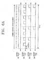
- FIG. 6A shows a method for transmitting a signal according to a regular or gated transmission pattern for the uplink DPCCH in case of there is no DPDCH data for a predetermined period of time according to an embodiment of the present invention.
- reference numerals 301, 302, 303 and 304 show different gating rates according to a ratio of a duty cycle (hereinafter, referred to as DC).
- the above gating rate transition method can be divided into several methods as stated below, and is determined according to system setup.
- FIG. 6B shows a method for transmitting a signal according to a regular or gated transmission pattern for the uplink DPCCH in case of there is no DPDCH data for a predetermined period of time according to another embodiment of the present invention.
- reference numerals 305, 306 and 307 show different gating rates according to a ratio of a duty cycle DC.
- the above gating rate transition method can be divided into several methods as stated below, and is determined according to system setup.
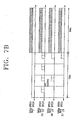
- FIGS. 7A and 7B show the uplink DPCCH for the case where a transition message is transmitted over the uplink DPDCH when a dedicated MAC (Medium Access Control) logical channel is generated in case of there is nok DPDCH data for a predetermined period of time of FIGS. 6A and 6B .
- the power control groups are transmitted according to the gated transmission patterns in the first frame, and then undergo normal transmission when the uplink DPDCH is transmitted in the second frame.
- the TPC bits for downlink power control can be omitted and the pilot duration (or period) can be extended to a power control group length.
- the power control groups which are transmitted according to the gated transmission pattern, undergo normal transmission for transmit the downlink DPDCH.
- the TPC bits for downlink power control can be omitted and the pilot duration can be extended to a power control group length.
- the power control groups, as shown by the reference numerals 315, 316 and 317, are transmitted according to the gated transmission patterns, and then undergo normal transmission for transmit the downlink DPDCH message.
- the TPC bits for downlink power control can be omitted and the pilot duration (or period) can be extended to a power control group length.
- FIG. 8A shows a method for transmitting downlink and uplink signals when transmission of a downlink DPDCH is discontinued.
- the base station and the mobile station start gating transmission if a set timer value expires or a downlink DPDCH message for state transition is generated.
- FIG. 8A shows an embodiment where the message for start gating transmission is generated by the base station, it is also possible for the mobile station to send a gating-request message to the base station when there is no downlink and uplink DPDCH. While transmitting the downlink DPCCH in FIG.
- the mobile station ignores the meaningless TPC values transmitted from the base station in order to perform uplink power control in consideration of the gating pattern for the uplink DPCCH, and performs transmission at the same transmission power as the transmission power for the previous power control group.
- the downlink DPCCH in FIG. 8A it is also possible to gate only the TFCI and TPC bits in the downlink DPCCH without gating the pilot symbols in the downlink DPCCH.
- the gating pattern is identical to a gating pattern for the uplink DPCCH of the mobile station.
- the power control group in which the TPC bits in the downlink DPCCH are gated, refers to the TPC bits generated by measuring the pilot symbols corresponding to the gated power control group in the DPCCH transmitted from the mobile station.
- Reference numeral 802 shows a situation where a message for gated transmission is generated by the base station and is transmitted to the mobile station over the downlink DPDCH.
- FIG. 8B shows a method for transmitting downlink and uplink signals when transmission of a uplink DPDCH is discontinued.
- the base station and the mobile station make the gated transmission at a time point appointed (or scheduled) between them when a set timer value expires or after exchanging a gated transmission message.
- FIG. 8B shows an embodiment where the message for gated transmission is generated in the downlink DPDCH, the gated transmission message can also be generated in the uplink DPDCH of the mobile station. While transmitting the downlink DPCCH in FIG.
- the mobile station ignores the meaningless TPC values transmitted from the base station in order to perform uplink power control in consideration of the gating pattern for the uplink DPCCH, and performs transmission at the same transmission power as the transmission power for the previous power control group.
- the downlink DPCCH in FIG. 8B it is also possible to gate only the TFCI and TPC bits in the downlink DPCCH without gating the pilot symbols in the downlink DPCCH.
- the gating pattern is identical to a gating pattern for the uplink DPCCH of the mobile station.
- the power control group in which the TPC bits in the downlink DPCCH are gated, refers to the TPC bits generated by measuring the pilot symbols corresponding to the gated power control group in the DPCCH transmitted from the mobile station.
- Reference numeral 804 shows a situation where a gated transmission message generated by the base station is transmitted to the mobile station over the downlink DPDCH.
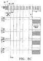
- FIG. 8C shows a method for transmitting downlink and uplink signals when transmission of a downlink DPDCH is discontinued.
- the base station and the mobile station start gated transmission if a set timer value expires or a downlink DPDCH message for start gated transmission is transmitted.
- FIG. 8C shows an embodiment where the message for gated transmission message is generated by the base station, it is also possible for the mobile station to send a gated transmission request message to the base station when there is no downlink and uplink DPDCH. While transmitting the downlink DPCCH in FIG.
- the mobile station ignores the meaningless TPC values transmitted from the base station in order to perform uplink power control in consideration of the gating pattern for the uplink DPCCH, and performs transmission at the same transmission power as the transmission power for the previous power control group.
- the downlink DPCCH in FIG. 8C it is also possible to gate only the TFCI and TPC bits in the downlink DPCCH without gating the pilot symbols in the downlink DPCCH.
- the gating pattern is identical to a gating pattern for the uplink DPCCH of the mobile station.
- the power control group in which the TPC bits in the downlink DPCCH are gated, refers to the TPC bits generated by measuring the pilot symbols corresponding to the gated power control group in the DPCCH transmitted from the mobile station.
- Reference numeral 806 shows a situation where a gated transmission message is generated by the mobile station and is transmitted to the base station over the uplink DPDCH.
- FIG. 8D shows a method for transmitting downlink and uplink signals when transmission of a uplink DPDCH is discontinued.
- the base station and the mobile station can start gated transmission at a time point appointed (or scheduled) between them when a set timer value expires or after exchanging a gated transmission message.
- FIG. 8D shows an embodiment where the message for gated transmission is generated in the downlink DPDCH, the gated transmission message can also be generated in the uplink DPDCH of the mobile station. While transmitting the downlink DPCCH in FIG.
- the mobile station ignores the meaningless TPC values transmitted from the base station in order to perform uplink power control in consideration of the gating pattern for the uplink DPCCH, and performs transmission at the same transmission power as the transmission power for the previous power control group.
- the downlink DPCCH in FIG. 8D it is also possible to gate only the TFCI and TPC bits in the downlink DPCCH without gating the pilot symbols in the downlink DPCCH.
- the gating pattern is identical to a gating pattern for the uplink DPCCH of the mobile station.
- the power control group in which the TPC bits in the downlink DPCCH are gated, refers to the TPC bits generated by measuring the pilot symbols corresponding to the gated power control group in the DPCCH transmitted from the mobile station.
- Reference numeral 808 shows a situation where a gated transmission message generated by the mobile station is transmitted to the base station over the uplink DPDCH.
- FIG. 9A shows a method for transmitting downlink and uplink signals when transmission of a downlink DPDCH is discontinued.
- the base station and the mobile station can start gated transmission at a time point appointed between them if a set timer value expires or after exchanging a gated transmission message.
- FIG. 9A shows a case where a gating pattern for the downlink DPCCH 501 is identical to a gating pattern for the uplink DPCCH 503.
- FIG. 9A shows an embodiment where the gated transmission message is generated through the downlink DPDCH, the gated transmission message can also be generated through the uplink DPDCH of the mobile station.
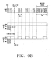
- FIG. 9B shows a method for transmitting downlink and uplink signals when transmission of a uplink DPDCH is discontinued.
- the base station and the mobile station make a state transition at a time point appointed between them if a set timer value expires or after exchanging a state transition message.
- FIG. 9B shows a case where a gating pattern for the downlink DPCCH is identical to a gating pattern for the uplink DPCCH.
- FIG. 9B shows an embodiment where the state transition message is generated through the downlink DPDCH, the state transition message can also be generated through the uplink DPDCH of the mobile station.
- the downlink and uplink frames have the same frame starting point.
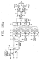
- FIGS. 10A and 10B show structures of the base station controller and the mobile station controller, respectively, which enable such gated transmission.
- FIG. 10A shows a structure of the base station controller according to another embodiment of the present invention.
- the base station transmitter is different from FIG. 4A in that the pilot, TFCI and TPC bits constituting the downlink DPCCH can be separately gated according to different gating patterns by the gated transmission controller 141. That is, the gated transmission controller 141 performs gated transmission on the pilot, TFCI and TPC bits for the downlink DPCCH at a power control group (or time slot) scheduled with the mobile station in the control-only substate where the traffic data is not transmitted over the downlink and uplink DPDCHs.
- the gated transmission controller 141 By using the gated transmission controller 141, it is also possible to assemble a pilot of a nth slot and TFCI and TPC bits of a (n+1)th slot into a gated transmission unit.
- the base station transmits signaling data using the gated transmission controller 141 during gated transmission in the control-only substate, it is possible to avoid performing gated transmission on the pilot and TFCI at the duration where the signaling data is transmitted.
- the gated transmission controller 141 can perform gated transmission on one power control group (or one entire slot) including the pilot symbols, TFCI and TPC bits for the downlink DPCCH at a power control group (or time slot) scheduled with the mobile station in the control-only substate when the traffic data is not transmitted over the downlink and uplink DPDCHs.
- the downlink gated transmission pattern is identical to the uplink gated transmission pattern, there can exist an offset therebetween for efficient power control.
- the offset is given as a system parameter.
- FIG. 10B shows a structure of the mobile station transmitter according to another embodiment of the present invention.
- the mobile station transmitter is different from FIG. 4B in that the pilot, TFCI, FBI and TPC bits constituting the uplink DPCCH can be separately gated according to different patterns by the gated transmission controller 241.
- the gated transmission controller 241 gates transmission of the pilot, FTCI, FBI and TPC bits for the uplink DPCCH at a power control group (or time slot) scheduled with the mobile station in the control-only substate when the traffic data is not transmitted over the downlink and uplink DPDCHs.
- the base station transmits signaling data using the gated transmission controller 241 during gated transmission in the control-only substate, it is possible to avoid performing gated transmission on the pilot and TFCI at the duration when the signaling data is transmitted.
- the gated transmission controller 241 can perform gated transmission on one power control group (or one entire slot) including the pilot symbols, TFCI, FBI and TPC bits for the uplink DPCCH at a power control group (or time slot) scheduled with the mobile station in the control-only substate when the traffic data is not transmitted over the downlink and uplink DPDCHs.
- the downlink gated transmission pattern is identical to the uplink gated transmission pattern, there can exist an offset therebetween for efficient power control.
- the offset is given as a system parameter.
- FIGS. 11A to 11E and FIGS. 12A to 12E show signal transmission diagrams for gated transmission performed by the base station and the mobile station transmitters of FIGS. 10A and 10B .
- FIGS. 11A to 11E show how to perform gated transmission when the frame length is 10msec and each frame includes 16 power control groups, i.e., each power control group has a length of 0.625msec.
- FIGS. 12A to 12E show how to perform gated transmission when the frame length is 10msec and each frame includes 15 power control groups, i.e., each power control group has a length of 0.667msec.
- FIG. 11A shows gated transmission for the downlink and uplink DPCCHs according to a first embodiment of the present invention.
- a gated transmission unit for the downlink DPCCH may not be a slot unit. That is, with regard to two adjacent slots, a pilot symbol of an predetermined nth slot and TFCI and TPC bits of an (n+1)th slot are set as a gated transmission unit for the downlink DPCCH because of the pilot symbol is used for channel estimatin to detect the TFCI and TPC. For example, when the gating rate is 1/2, a pilot symbol of slot number 0 and TFCI and TPC bits of slot number 1 are set as a gated transmission unit for the downlink DPCCH.
- a pilot symbol of slot number 2 and TFCI and TPC bits of slot number 3 are set as a gated transmission unit for the downlink DPCCH.
- a pilot symbol of slot number 6 and TFCI and TPC bits of slot number 7 are set as a gated transmission unit for the downlink DPCCH.
- the gated transmission unit for the downlink DPCCH is set to be different from the actual slot unit, since an nth pilot symbol may be required in the receiver to demodulate the (n+1)th TPC according to a demodulation method for the TPC signal.
- the TPC for the downlink DPCCH and the TPC for the uplink DPCCH are located at slot number 15 (i.e., the 16 th slot, which is the last slot of the nth frame), so that the first slot of the (n+1)th frame is power controlled using the TPC bits existing in the last slot of an nth frame. That is, the TPC for power controlling the first slot of the next frame is located at the last slot of the present frame.
- an offset between the downlink and uplink frame start points is fixed to 250 ⁇ sec.
- the offset value can be changed to an arbitrary value while the base station and the mobile station exchange a parameter for DPCCH gated transmission in the call setup process.
- the offset value is set to a proper value in consideration of propagation delay of the base station and the mobile station in the call setup process. That is, when the cell radius is over 30Km, the offset value can be set to a value larger than the conventional offset value of 250 ⁇ sec for DPCCH gated transmission, and this value can be determined through experiments.
- FIG. 11B shows gated transmission for the downlink and uplink DPCCHs according to a second embodiment of the present invention.
- FIG. 11B shows a case where transmission of the downlink DPCCH goes ahead of transmission of the uplink DPCCH during gated transmission, for the gating rates of 1/2, 1/4 and 1/8.
- the difference i.e., offset
- DL-UL timing for the gating rates of 1/2, 1/4 and 1/8.
- a pilot symbol of the predetermined-nth slot and TFCI and TPC of the (n+1)th slot are set as a gated transmission unit for the downlink DPCCH.
- a pilot symbol of slot number 0 and TFCI and TPC of slot number 1 are set as a gated transmission unit for the downlink DPCCH.
- a pilot symbol of slot number 2 and TFCI and TPC of slot number 3 are set as a gated transmission unit for the downlink DPCCH.
- a pilot symbol of slot number 6 and TFCI and TPC of slot number 7 are set as a gated transmission unit for the downlink DPCCH.
- the TPC for power controlling the first slot of the next frame is located at the last slot of the present frame. That is, the TPC for the downlink DPCCH and the TPC for the uplink DPCCH are both located at slot number 15 (i.e., the 16 th slot).
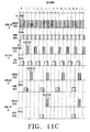
- FIG. 11C shows gated transmission for the downlink and uplink DPCCHs according to a third embodiment of the present invention.
- FIG. 11C shows a case where transmission of the uplink DPCCH goes ahead of transmission of the downlink DPCCH during gated transmission, for the gating rates of 1/2, 1/4 and 1/8.
- a pilot symbol of the predetermined nth slot and TFCI and TPC of the (n+1)th slot are set as a gated transmission unit for the downlink DPCCH.
- a pilot symbol of slot number 1 and TFCI and TPC of slot number 2 are set as a gated transmission unit for the downlink DPCCH.
- a pilot symbol of slot number 2 and TFCI and TPC of slot number 3 are set as a gated transmission unit for the downlink DPCCH.
- a pilot symbol of slot number 6 and TFCI and TPC of slot number 7 are set as a gated transmission unit for the downlink DPCCH.
- the TPC for power controlling the first slot of the next frame is located at the last slot of the present frame. That is, the TPC for the downlink DPCCH and the TPC for the uplink DPCCH are both located at a slot number 15 (i.e., the 16 th slot).
- FIG. 11D shows gated transmission for the downlink and uplink DPCCHs according to a fourth embodiment of the present invention.
- FIG. 11D shows a case where for the gating rates of 1/2, 1/4 and 1/8, transmission of the downlink DPCCH goes ahead of transmission of the uplink DPCCH during gated transmission, and the downlink and uplink gating patterns are set to the same period.
- a pilot symbol of the predetermined nth slot and TFCI and TPC of the (n+1)th slot are set as a gated transmission unit for the downlink DPCCH.
- a pilot symbol of slot number 0 and TFCI and TPC of slot number 1 are set as a gated transmission unit for the downlink DPCCH.
- a pilot symbol of slot number 0 and TFCI and TPC of slot number 1 are set as a gated transmission unit for the downlink DPCCH.
- a pilot symbol of slot number 2 and TFCI and TPC of slot number 3 are set as a gated transmission unit for the downlink DPCCH.
- the TPC for power controlling the first slot of the next frame is located at the last slot of the present frame. That is, the TPC for the downlink DPCCH and the TPC for the uplink DPCCH are both located at slot number 15 (i.e., the 16 th slot).
- FIG. 11E shows gated transmission for the downlink and uplink DPCCHs according to a fifth embodiment of the present invention.
- FIG. 11E shows a case where for the gating rates of 1/2, 1/4 and 1/8, transmission of the uplink DPCCH goes ahead of transmission of the downlink DPCCH during gated transmission, and the downlink and uplink gating patterns are set to the same period.
- a pilot symbol of the nth slot and TFCI and TPC of the (n+1)th slot are set as a gated transmission unit for the downlink DPCCH.
- a pilot symbol of slot number 1 and TFCI and TPC of slot number 2 are set as a gated transmission unit for the downlink DPCCH.
- a pilot symbol of slot number 2 and TFCI and TPC of slot number 3 are set as a gated transmission unit for the downlink DPCCH.
- a pilot symbol of slot number 6 and TFCI and TPC of slot number 7 are set as a gated transmission unit for the downlink DPCCH.
- the TPC for power controlling the first slot of the next frame is located at the last slot of the present frame. That is, the TPC for the downlink DPCCH and the TPC for the uplink DPCCH are both located at a slot number 15 (i.e., the 16 th slot).
- FIG. 12A shows gated transmission for the downlink and uplink DPCCHs according to a sixth embodiment of the present invention.
- FIG. 12A shows a case where a gating rate for gated transmission of the downlink and uplink DPCCHs is 1/3, i.e., gated transmission is performed at the periods corresponding to 1/3 power control groups of the whole power control groups. That is, gated transmission is performed at the periods corresponding to 5 power control groups out of the whole 15 power control groups.
- a gated transmission unit for the downlink DPCCH is set to be different from a slot unit.
- a pilot symbol of the predetermined nth slot and TFCI and TPC of the (n+1)th slot are set as a gated transmission unit for the downlink DPCCH because of the pilot symbol is used for channel estimation to detect the TFCI and the TPC.
- ⁇ Case 1> shows a case where the uplink DPCCH and the downlink DPCCH are transmitted at the same time during gated transmission, and the downlink and uplink gating patterns are set to the same period.
- a pilot symbol of slot number I and TFCI and TPC of slot number 2 are set as a gated transmission unit for the downlink DPCCH
- a pilot symbol of slot number 4 and TFCI and TPC of slot number 5 are set as a gated transmission unit for the downlink DPCCH
- a pilot symbol of slot number 7 and TFCI and TPC of slot number 8 are set as a gated transmission unit for the downlink DPCCH
- a pilot symbol of slot number 10 and TFCI and TPC of slot number 11 are set as a gated transmission unit for the downlink DPCCH
- a pilot symbol of slot number 13 and TFCI and TPC of slot number 14 are set as a gated transmission unit for the downlink DPCCH.
- ⁇ Case 2> shows a case where transmission of the uplink DPCCH occurs before transmission of the downlink DPCCH during gated transmission.
- a pilot symbol of slot number 0 and TFCI and TPC of slot number 1 are set as a gated transmission unit for the downlink DPCCH
- a pilot symbol of slot number 3 and TFCI and TPC of slot number 4 are set as a gated transmission unit for the downlink DPCCH
- a pilot symbol of slot number 6 and TFCI and TPC of slot number 7 are set as a gated transmission unit for the downlink DPCCH
- a pilot symbol of slot number 9 and TFCI and TPC of slot number 10 are set as a gated transmission unit for the downlink DPCCH
- a pilot symbol of slot number 12 and TFCI and TPC of slot number 13 are set as a gated transmission unit for the downlink DPCCH.
- ⁇ Case 3> shows a case where transmission of the uplink DPCCH occurs before transmission of the downlink DPCCH during gated transmission.
- a pilot symbol of slot number 1 and TFCI and TPC of slot number 2 are set as a gated transmission unit for the downlink DPCCH;
- a pilot symbol of slot number 4 and TFCI and TPC of slot number 5 are set as a gated transmission unit for the downlink DPCCH;
- a pilot symbol of slot number 7 and TFCI and TPC of slot number 8 are set as a gated transmission unit for the downlink DPCCH;
- a pilot symbol of slot number 10 and TFCI and TPC of slot number 11 are set as a gated transmission unit for the downlink DPCCH;
- a pilot symbol of slot number 13 and TFCI and TPC of slot number 14 are set as a gated transmission unit for the downlink DPCCH.
- ⁇ Case 4> shows a case where transmission of the uplink DPCCH occurs after transmission of the downlink DPCCH during gated transmission.
- a pilot symbol of slot number 14 and TFCI and TPC of slot number 0 are set as a gated transmission unit for the downlink DPCCH
- a pilot symbol of slot number 2 and TFCI and TPC of slot number 3 are set as a gated transmission unit for the downlink DPCCH
- a pilot symbol of slot number 5 and TFCI and TPC of slot number 6 are set as a gated transmission unit for the downlink DPCCH
- a pilot symbol of slot number 8 and TFCI and TPC of slot number 9 are set as a gated transmission unit for the downlink DPCCH
- a pilot symbol of slot number 11 and TFCI and TPC of slot number 12 are set as a gated transmission unit for the downlink DPCCH.
- ⁇ Case 5> shows a case where transmission of the uplink DPCCH occurs after transmission of the downlink DPCCH during gated transmission.
- a pilot symbol of slot number 0 and TFCI and TPC of slot number 1 are set as a gated transmission unit for the downlink DPCCH
- a pilot symbol of slot number 3 and TFCI and TPC of slot number 4 are set as a gated transmission unit for the downlink DPCCH
- a pilot symbol of slot number 6 and TFCI and TPC of slot number 7 are set as a gated transmission unit for the downlink DPCCH
- a pilot symbol of slot number 9 and TFCI and TPC of slot number 10 are set as a gated transmission unit for the downlink DPCCH
- a pilot symbol of slot number 12 and TFCI and TPC of a slot number 13 are set as a gated transmission unit for the downlink DPCCH.
- FIG. 12B shows gated transmission for the downlink and uplink DPCCHs according to a seventh embodiment of the present invention.
- FIG. 12A shows a case where the gating rate for gated transmission of the downlink and uplink DPCCHs is 1/5, i.e., gated transmission is performed so that 1/5 of the power control groups are transmitted in comparison to all the power control groups in standard transmission. That is, gated transmission is performed so that 3 power control groups out of the standard 15 power control groups are transmitted.
- a gated transmission unit for the downlink DPCCH is set to be different from a slot unit.
- a pilot symbol of the predetermined nth slot and TFCI and TPC of the (n+1)th slot are set as a gated transmission unit for the downlink DPCCH because of the pilot symbol is used for channel estimation to detect the TFCI and the TPC.
- a pilot symbol of slot number 3 and TFCI and TPC of slot number 4 are set as a gated transmission unit for the downlink DPCCH; a pilot symbol of slot number 8 and TFCI and TPC of slot number 9 are set as a gated transmission unit for the downlink DPCCH; and a pilot symbol of slot number 13 and TFCI and TPC of slot number 14 are set as a gated transmission unit for the downlink DPCCH.
- FIG. 12C shows gated transmission for the downlink and uplink DPCCHs according to an eighth embodiment of the present invention.
- the gating pattern is set such that the last power control group of the uplink DPCCH should not be gated in the control-only substate.
- Such a gating pattern has high channel estimation performance, since the base station can perform channel estimation using the pilot symbols in the last power control group of the frame.
- FIG. 12D shows gated transmission for the downlink and uplink DPCCHs according to a ninth embodiment of the present invention. Shown is a gating pattern for transmitting a downlink message during gated transmission in the control-only substate.
- gated transmission is discontinued for the pilot and TFCI, and only the TPC continues to undergo gated transmission according to the gating pattern.
- the pilot symbols and TFCI as well as TPC undergo gated transmission.
- the pilot symbol is transmitted at the 0 th , 3 rd , 6 th , 9 th and 12 th slots only, and the TFCI and TPC bits are transmitted at the 1 st , 4 th , 7 th , 10 th and 13 th slots only.
- the pilot symbol and TFCI are transmitted at every slot, whereas TPC is transmitted at the 1 st , 4 th , 7 th 10 th and 13 th slots only. Accordingly, even though downlink transmission data is generated during gated transmission, the power control rate is maintained.
- FIG. 12E shows gated transmission for the downlink and uplink DPCCHs according to a tenth embodiment of the present invention. Shown is a gating pattern for transmitting a uplink message during gated transmission in the control-only substate. For a period where the uplink data (message) is not transmitted, the pilot symbols and TFCI as well as TPC and FBI undergo gated transmission. The pilot symbol, TFCI, FBI and TPC are transmitted at 2 nd , 5 th , 8 th 11 th and 14 th slots only.
- the pilot symbol and TFCI are transmitted at every slot, whereas TPC and FBI are transmitted at the 2 nd , 5 th , 8 th , 11 th and 14 th slots only. Accordingly, even though uplink transmission data is generated during gated transmission, the power control rate is maintained.
- the invention minimizes the time required for the sync reacquisition process in the base station, minimizes interference as well as uplink DPCCH transmission time, and minimizes interference due to the transmission of the uplink power control bit over the downlink, all of which increases the capacity of the mobile communication system.
Claims (3)
- Verfahren zum Übertragen von Abwärtsverbindungssignalen von einer Basisstation an eine Mobilstation eines Mobilkommunikationssystems, in dem Basisstationen im Vergleich zu anderen Basisstationen asynchron arbeiten, wobei das Abwärtsverbindungssignal ein dediziertes physikalisches Datenkanalsignal und ein dediziertes physikalisches Steuerkanalsignal beinhaltet, wobei das in der Basisstation durchgeführte Verfahren die nachfolgenden Schritte umfasst:Bestimmen, ob die Basisstation Abwärtsverbindungsdaten zur Übertragung an die Mobilstation auf dem dedizierten physikalischen Datenkanal hat; undTorsteuern (gating) einer Übertragung des dedizierten physikalischen Steuerkanalsignals entsprechend einem vorbestimmten torgesteuerten (gated) Ein- oder Aus-Muster bei Nichtvorhandensein von Daten zur Übertragung auf dem dedizierten physikalischen Datenkanal für eine vorbestimmte Zeitspanne,wobei das dedizierte physikalische Steuerkanalsignal Pilotsymbole, TFCI-Bits (Transport Format Combination Indicator, Transportformatkombinationsindikator) und ein Leistungssteuerbit beinhaltet,wobei das dedizierte physikalische Steuerkanalsignal in einem torgesteuerten Ein-Schlitzformat übertragen wird, wobei der Schlitz das Leistungssteuerbit aufweist, das die Leistung der Aufwärtsverbindungsübertragung steuert.
- Verfahren nach Anspruch 1, wobei das Schlitzformat Pilotsymbole, TFCI-Bits und das Leistungssteuerbit beinhaltet und das vorbestimmte torgesteuerte Ein- oder Aus-Muster ein Muster zum Torsteuern (gating) einer Übertragung des Pilotsymbols in einem vorbestimmten n-ten Schlitz und der TFCI-Bits und des Leistungssteuerbits in einem (n+t)-ten Schlitz ist.
- Verfahren nach Anspruch 2, wobei die torgesteuerte Übertragung des Leistungssteuerbits regulär gehalten wird, wenn die Basisstation das dedizierte physikalische Datenkanalsignal an die Mobilstation auf dem dedizierten physikalischen Datenkanal überträgt.
Applications Claiming Priority (9)
| Application Number | Priority Date | Filing Date | Title |
|---|---|---|---|
| KR9913610 | 1999-04-12 | ||
| KR19990013610 | 1999-04-12 | ||
| KR9919080 | 1999-05-26 | ||
| KR19990019080 | 1999-05-26 | ||
| KR9927355 | 1999-07-07 | ||
| KR19990027355 | 1999-07-07 | ||
| KR19990027398 | 1999-07-08 | ||
| KR9927398 | 1999-07-08 | ||
| EP00921136A EP1169800A4 (de) | 1999-04-12 | 2000-04-12 | Verfahren und vorrichtung zur getorten übertragung in einem cdma nachrichtenübertragungssystem |
Related Parent Applications (1)
| Application Number | Title | Priority Date | Filing Date |
|---|---|---|---|
| EP00921136.8 Division | 2000-04-12 |
Publications (2)
| Publication Number | Publication Date |
|---|---|
| EP1420538A1 EP1420538A1 (de) | 2004-05-19 |
| EP1420538B1 true EP1420538B1 (de) | 2012-06-13 |
Family
ID=36709986
Family Applications (2)
| Application Number | Title | Priority Date | Filing Date |
|---|---|---|---|
| EP00921136A Ceased EP1169800A4 (de) | 1999-04-12 | 2000-04-12 | Verfahren und vorrichtung zur getorten übertragung in einem cdma nachrichtenübertragungssystem |
| EP20030019386 Expired - Lifetime EP1420538B1 (de) | 1999-04-12 | 2000-04-12 | Procédé de transmission intermittente dans un système de télécommunication à AMRC |
Family Applications Before (1)
| Application Number | Title | Priority Date | Filing Date |
|---|---|---|---|
| EP00921136A Ceased EP1169800A4 (de) | 1999-04-12 | 2000-04-12 | Verfahren und vorrichtung zur getorten übertragung in einem cdma nachrichtenübertragungssystem |
Country Status (9)
| Country | Link |
|---|---|
| US (1) | US6747963B1 (de) |
| EP (2) | EP1169800A4 (de) |
| JP (2) | JP4435991B2 (de) |
| CN (1) | CN1186893C (de) |
| AU (1) | AU765329B2 (de) |
| BR (1) | BR0009713A (de) |
| CA (1) | CA2371958C (de) |
| IL (2) | IL145548A0 (de) |
| WO (1) | WO2000062456A1 (de) |
Families Citing this family (100)
| Publication number | Priority date | Publication date | Assignee | Title |
|---|---|---|---|---|
| US6081536A (en) | 1997-06-20 | 2000-06-27 | Tantivy Communications, Inc. | Dynamic bandwidth allocation to transmit a wireless protocol across a code division multiple access (CDMA) radio link |
| US6542481B2 (en) | 1998-06-01 | 2003-04-01 | Tantivy Communications, Inc. | Dynamic bandwidth allocation for multiple access communication using session queues |
| US7394791B2 (en) | 1997-12-17 | 2008-07-01 | Interdigital Technology Corporation | Multi-detection of heartbeat to reduce error probability |
| US9525923B2 (en) | 1997-12-17 | 2016-12-20 | Intel Corporation | Multi-detection of heartbeat to reduce error probability |
| IL139792A (en) * | 1999-04-12 | 2005-07-25 | Samsung Electronics Co Ltd | Method for controlling gated transmission of dedicated channel in w-cdma communication system |
| KR100492968B1 (ko) * | 1999-05-29 | 2005-06-07 | 삼성전자주식회사 | 부호분할다중접속 통신시스템의 제어유지 부상태에서의 단속적채널 송신 장치 및 방법 |
| CA2370670C (en) * | 2000-02-17 | 2007-06-19 | Samsung Electronics Co., Ltd. | Apparatus and method for assigning a common packet channel in a cdma communication system |
| JP3415102B2 (ja) | 2000-06-27 | 2003-06-09 | 日本電気株式会社 | Cdma通信の送信電力制御システム及びその送信電力制御方法 |
| CA2313314A1 (en) * | 2000-06-30 | 2001-12-30 | Frank Van Heeswyk | Control channel for a wireless digital subscriber line system |
| JP2002033716A (ja) * | 2000-07-18 | 2002-01-31 | Sony Corp | Cdma拡散方法およびcdma端末装置 |
| US7006428B2 (en) * | 2000-07-19 | 2006-02-28 | Ipr Licensing, Inc. | Method for allowing multi-user orthogonal and non-orthogonal interoperability of code channels |
| US8537656B2 (en) * | 2000-07-19 | 2013-09-17 | Ipr Licensing, Inc. | Method for compensating for multi-path of a CDMA reverse link utilizing an orthogonal channel structure |
| US7911993B2 (en) | 2000-07-19 | 2011-03-22 | Ipr Licensing, Inc. | Method and apparatus for allowing soft handoff of a CDMA reverse link utilizing an orthogonal channel structure |
| US6775254B1 (en) * | 2000-11-09 | 2004-08-10 | Qualcomm Incorporated | Method and apparatus for multiplexing high-speed packet data transmission with voice/data transmission |
| DE10056258B4 (de) * | 2000-11-14 | 2004-02-26 | Rohde & Schwarz Gmbh & Co. Kg | Verfahren zur Bestimmung und zur Anzeige der Leistungsanteile der Codes eines CDMA-Signals |
| WO2002056297A1 (en) * | 2001-01-11 | 2002-07-18 | Sasken Communication Technologies Limited | Adaptive-block-length audio coder |
| US6970438B2 (en) * | 2001-02-16 | 2005-11-29 | Nokia Mobile Phones Ltd. | Method and device for downlink packet switching |
| JP3736429B2 (ja) | 2001-02-21 | 2006-01-18 | 日本電気株式会社 | セルラシステム、基地局、移動局並びに通信制御方法 |
| GB0108381D0 (en) * | 2001-04-04 | 2001-05-23 | Koninl Philips Electronics Nv | Radio communication system |
| CA2450458C (en) * | 2001-06-13 | 2015-04-07 | Interdigital Acquisition Corp. | System and method for coordination of wireless maintenance channel power control |
| CN1547861A (zh) | 2001-06-27 | 2004-11-17 | ���˹���Ѷ��� | 无线通信系统中控制信息的传递 |
| US6917581B2 (en) | 2001-07-17 | 2005-07-12 | Ipr Licensing, Inc. | Use of orthogonal or near orthogonal codes in reverse link |
| US7197282B2 (en) * | 2001-07-26 | 2007-03-27 | Ericsson Inc. | Mobile station loop-back signal processing |
| DE10137583A1 (de) * | 2001-08-01 | 2003-02-13 | Siemens Ag | Verfahren zum Betreiben eines Funksystems sowie entsprechend ausgestaltetes Funksystem und entsprechend ausgestalteter Sender und Empfänger |
| JP3577021B2 (ja) * | 2001-09-12 | 2004-10-13 | 埼玉日本電気株式会社 | 移動局および移動局における電界状態判定方法 |
| US7103021B2 (en) * | 2001-09-25 | 2006-09-05 | Qualcomm Incorporated | Method and apparatus for communications of data rate control information in a CDMA communication system |
| DE10149544B4 (de) * | 2001-10-08 | 2004-11-11 | Rohde & Schwarz Gmbh & Co. Kg | Verfahren zum Ermitteln des Zeitversatzes eines CDMA-Signals und Computerprogramm zur Durchführung des Verfahrens |
| KR100533205B1 (ko) | 2001-10-17 | 2005-12-05 | 닛본 덴끼 가부시끼가이샤 | 이동 통신 시스템, 통신 제어 방법, 이것에 사용되는기지국 및 이동국 |
| US6845088B2 (en) * | 2001-10-19 | 2005-01-18 | Interdigital Technology Corporation | System and method for fast dynamic link adaptation |
| US7269448B2 (en) * | 2001-11-09 | 2007-09-11 | Electronics And Telecommunications Research Institute | Method for recognizing request for data transmission by mobile/base station RRC using network transfer device |
| JP3594086B2 (ja) * | 2002-02-08 | 2004-11-24 | ソニー株式会社 | 移動体通信における情報多重方法、伝送フォーマット組合せ識別子のデコード方法および装置、移動局装置、基地局装置および移動体通信システム |
| FI115742B (fi) * | 2002-03-28 | 2005-06-30 | Valtion Teknillinen | Tehonsäätömenetelmä ja tietoliikennejärjestelmä |
| TWI332326B (en) | 2002-10-17 | 2010-10-21 | Interdigital Tech Corp | Power control for communications systems utilizing high speed shared channels |
| US8134976B2 (en) | 2002-10-25 | 2012-03-13 | Qualcomm Incorporated | Channel calibration for a time division duplexed communication system |
| US20040081131A1 (en) | 2002-10-25 | 2004-04-29 | Walton Jay Rod | OFDM communication system with multiple OFDM symbol sizes |
| US8320301B2 (en) | 2002-10-25 | 2012-11-27 | Qualcomm Incorporated | MIMO WLAN system |
| US8208364B2 (en) | 2002-10-25 | 2012-06-26 | Qualcomm Incorporated | MIMO system with multiple spatial multiplexing modes |
| US7986742B2 (en) | 2002-10-25 | 2011-07-26 | Qualcomm Incorporated | Pilots for MIMO communication system |
| US7002900B2 (en) | 2002-10-25 | 2006-02-21 | Qualcomm Incorporated | Transmit diversity processing for a multi-antenna communication system |
| US8363593B2 (en) * | 2002-11-06 | 2013-01-29 | Alcatel Lucent | Method for carrying downlink control information for an enhanced uplink dedicated channel |
| US6882857B2 (en) | 2002-11-26 | 2005-04-19 | Qualcomm, Incorporated | Method and apparatus for efficient processing of data for transmission in a communication system |
| CN100442907C (zh) | 2003-01-23 | 2008-12-10 | 富士通株式会社 | 通信资源管理装置 |
| CN101997589B (zh) | 2003-01-23 | 2013-05-29 | 高通股份有限公司 | 在多址无线通信系统中提供发射分集的方法和装置 |
| JP2004297231A (ja) * | 2003-03-26 | 2004-10-21 | Nec Corp | 移動通信システム、無線基地局装置及びそれらに用いる電力制御方法 |
| US7283492B2 (en) * | 2003-10-02 | 2007-10-16 | Qualcomm Incorporated | Systems and methods for multiplexing control information onto a physical data channel |
| US7474643B2 (en) * | 2003-10-02 | 2009-01-06 | Qualcomm Incorporated | Systems and methods for communicating control data using multiple slot formats |
| UA83256C2 (ru) * | 2003-10-02 | 2008-06-25 | Квелкомм Инкорпорэйтед | Система и способ мультиплексирования данных управления для множества каналов передачи данных в одном канале управления (варианты) |
| US9473269B2 (en) | 2003-12-01 | 2016-10-18 | Qualcomm Incorporated | Method and apparatus for providing an efficient control channel structure in a wireless communication system |
| KR101013227B1 (ko) * | 2004-06-21 | 2011-02-10 | 노키아 코포레이션 | Hsdpa/단편적 dpch를 통한 끊어진 시그날링접속의 복구 방법 |
| KR20090008479A (ko) * | 2004-09-15 | 2009-01-21 | 가부시키가이샤 엔.티.티.도코모 | 이동 통신 시스템, 무선 제어국, 무선 기지국, 이동국 및 이동 통신 방법 |
| EP1830489B1 (de) * | 2004-11-19 | 2016-02-24 | NTT DoCoMo, Inc. | Mobilkommunikationsverfahren und mobilstation |
| CN105071898B (zh) * | 2004-12-28 | 2018-06-29 | 富士通株式会社 | 控制信道传输方法、基站以及终端 |
| KR20110045104A (ko) | 2004-12-28 | 2011-05-03 | 콘텐트가드 홀딩즈 인코포레이티드 | 라이센스 중심의 콘텐츠 소비를 위한 방법, 시스템, 및 장치 |
| WO2006082627A1 (ja) * | 2005-02-01 | 2006-08-10 | Mitsubishi Denki Kabushiki Kaisha | 送信制御方法、移動局および通信システム |
| CN101142770B (zh) | 2005-03-18 | 2011-12-28 | 株式会社Ntt都科摩 | 发送功率控制方法、移动台、无线基站及无线线路控制台 |
| TWI379605B (en) * | 2005-04-26 | 2012-12-11 | Nokia Corp | Method, system, apparatus and software product for combination of uplink dedicated physical control channel gating and enhanced uplink dedicated channel to improve capacity |
| US7466749B2 (en) | 2005-05-12 | 2008-12-16 | Qualcomm Incorporated | Rate selection with margin sharing |
| EP1911217B1 (de) | 2005-08-05 | 2014-09-24 | Nokia Corporation | Koordinierung eines aufwärtsstrecken-steuerkanal-sendung mit einer kanalqualitätsindikator-meldung |
| BRPI0614783B1 (pt) * | 2005-08-05 | 2019-06-25 | Nokia Technologies Oy | Método, equipamento de usuário, elemento de rede e sistema de comunicação |
| PL1917726T3 (pl) * | 2005-08-16 | 2016-03-31 | Koninklijke Philips Nv | Przystosowanie formatu kanału sterowania do nieciągłej transmisji danych |
| US8630602B2 (en) | 2005-08-22 | 2014-01-14 | Qualcomm Incorporated | Pilot interference cancellation |
| US9071344B2 (en) * | 2005-08-22 | 2015-06-30 | Qualcomm Incorporated | Reverse link interference cancellation |
| US8743909B2 (en) * | 2008-02-20 | 2014-06-03 | Qualcomm Incorporated | Frame termination |
| US8594252B2 (en) | 2005-08-22 | 2013-11-26 | Qualcomm Incorporated | Interference cancellation for wireless communications |
| US9014152B2 (en) * | 2008-06-09 | 2015-04-21 | Qualcomm Incorporated | Increasing capacity in wireless communications |
| US8611305B2 (en) | 2005-08-22 | 2013-12-17 | Qualcomm Incorporated | Interference cancellation for wireless communications |
| CN101026432B (zh) * | 2006-02-17 | 2011-08-10 | 华为技术有限公司 | 基于高速分组信道的分组数据业务传输方法及其系统 |
| US20070259682A1 (en) * | 2006-05-08 | 2007-11-08 | Jorma Kaikkonen | Enhanced uplink power control with gated uplink of control information |
| US7953376B2 (en) | 2006-06-20 | 2011-05-31 | Nokia Corporation | Synchronization method for discontinuous transmissions in a communications network |
| ES2312091T3 (es) * | 2006-07-14 | 2009-02-16 | Research In Motion Limited | Un metodo y un aparato para reducir la interferencia de enlace durante el abandono de una conexion entre un componente del equipo de usuario y un componente de la red de acceso. |
| US8565195B2 (en) * | 2006-08-21 | 2013-10-22 | Nokia Corporation | Apparatus, methods and computer program products providing support for packet data user continuous uplink connectivity |
| JP4910657B2 (ja) * | 2006-11-27 | 2012-04-04 | 富士通株式会社 | 移動無線ネットワーク制御方法及び装置 |
| KR20080092222A (ko) | 2007-04-11 | 2008-10-15 | 엘지전자 주식회사 | Tdd 시스템에서의 데이터 전송 방법 |
| CN101335987B (zh) * | 2007-06-28 | 2012-07-04 | 中兴通讯股份有限公司 | 无线网络控制器获取基站时隙格式能力的方法 |
| EP2197236B1 (de) * | 2007-10-02 | 2013-11-06 | Fujitsu Limited | Handover-steuereinrichtung, mobilstation, basisstation, handover-steuerserver und handover-steuerverfahren |
| US8838160B2 (en) | 2008-06-02 | 2014-09-16 | Telefonaktiebolaget Lm Ericsson (Publ) | Gating control loop technique for optimizing performance in a wireless communication network |
| RU2459363C1 (ru) * | 2008-06-09 | 2012-08-20 | Квэлкомм Инкорпорейтед | Увеличение пропускной способности в беспроводной связи |
| CN101605375B (zh) * | 2008-06-11 | 2011-02-09 | 大唐移动通信设备有限公司 | 一种下行控制信道上的信令发送方法 |
| US9237515B2 (en) * | 2008-08-01 | 2016-01-12 | Qualcomm Incorporated | Successive detection and cancellation for cell pilot detection |
| US9277487B2 (en) | 2008-08-01 | 2016-03-01 | Qualcomm Incorporated | Cell detection with interference cancellation |
| US20100097955A1 (en) * | 2008-10-16 | 2010-04-22 | Qualcomm Incorporated | Rate determination |
| JP4731596B2 (ja) * | 2008-11-25 | 2011-07-27 | 富士通株式会社 | 通信資源管理装置、移動端末及び方法 |
| KR101715938B1 (ko) | 2009-03-03 | 2017-03-14 | 엘지전자 주식회사 | 다중 안테나 시스템에서 harq ack/nack 신호 전송 방법 및 장치 |
| US9160577B2 (en) | 2009-04-30 | 2015-10-13 | Qualcomm Incorporated | Hybrid SAIC receiver |
| US8787509B2 (en) * | 2009-06-04 | 2014-07-22 | Qualcomm Incorporated | Iterative interference cancellation receiver |
| CN101645868B (zh) * | 2009-08-31 | 2014-12-10 | 中兴通讯股份有限公司 | 一种参考信号的发送方法和装置 |
| US8831149B2 (en) * | 2009-09-03 | 2014-09-09 | Qualcomm Incorporated | Symbol estimation methods and apparatuses |
| CN102668628B (zh) | 2009-11-27 | 2015-02-11 | 高通股份有限公司 | 增加无线通信中的容量的方法和装置 |
| KR101376676B1 (ko) | 2009-11-27 | 2014-03-20 | 퀄컴 인코포레이티드 | 무선 통신들에서의 용량 증가 |
| TWI393323B (zh) * | 2009-12-23 | 2013-04-11 | George Liu | 可攜式充電設備 |
| US9686815B2 (en) * | 2011-11-02 | 2017-06-20 | Qualcomm Incorporated | Devices and methods for managing discontinuous transmission at a wireless access terminal |
| US8774074B2 (en) | 2011-11-02 | 2014-07-08 | Qualcomm Incorporated | Apparatus and method for adaptively enabling discontinuous transmission (DTX) in a wireless communication system |
| CN102647778B (zh) * | 2012-03-29 | 2014-12-10 | 华为技术有限公司 | 一种功率控制方法、功率控制系统以及相关设备 |
| WO2013173537A1 (en) * | 2012-05-16 | 2013-11-21 | Nokia Corporation | Alternating adjustment of power levels for the data channel and control channel |
| US9119074B2 (en) * | 2012-06-05 | 2015-08-25 | Qualcomm Incorporated | Uplink downlink resource partitions in access point design |
| US9288760B2 (en) * | 2012-10-10 | 2016-03-15 | Qualcomm Incorporated | Method and apparatus for controlling uplink transmit power with optimum delay |
| CN104221314A (zh) * | 2013-03-22 | 2014-12-17 | 华为技术有限公司 | 控制信息传输方法及用户设备 |
| CN104125627B (zh) * | 2013-04-23 | 2019-08-06 | 中兴通讯股份有限公司 | 一种下行专用物理信道发射的方法和装置 |
| US20150094112A1 (en) * | 2013-09-27 | 2015-04-02 | Renesas Mobile Corporation | Power Control to Compensate Interference Level Changes |
| US10064215B2 (en) * | 2014-09-26 | 2018-08-28 | Qualcomm Incorporated | Enhanced transmission of control channel signaling over UMTS |
Family Cites Families (18)
| Publication number | Priority date | Publication date | Assignee | Title |
|---|---|---|---|---|
| US4675863A (en) * | 1985-03-20 | 1987-06-23 | International Mobile Machines Corp. | Subscriber RF telephone system for providing multiple speech and/or data signals simultaneously over either a single or a plurality of RF channels |
| US4787095A (en) * | 1987-03-03 | 1988-11-22 | Advanced Micro Devices, Inc. | Preamble search and synchronizer circuit |
| US5212685A (en) * | 1991-03-21 | 1993-05-18 | International Business Machines Corporation | Control circuit for half-duplex/simplex interface in communication system |
| ATE294441T1 (de) * | 1991-06-11 | 2005-05-15 | Qualcomm Inc | Vocoder mit veränderlicher bitrate |
| US5241542A (en) | 1991-08-23 | 1993-08-31 | International Business Machines Corporation | Battery efficient operation of scheduled access protocol |
| JPH06268575A (ja) * | 1993-03-12 | 1994-09-22 | Fujitsu Ltd | 移動通信システムのチャネルアクセス方式 |
| JPH06350547A (ja) * | 1993-06-03 | 1994-12-22 | Hitachi Ltd | ディジタル信号の多重化伝送方式 |
| FR2710805B1 (fr) | 1993-09-29 | 1995-11-10 | Alcatel Mobile Comm France | Structure de burst de remplissage dans un système cellulaire de radiocommunications numériques utilisant le principe de l'AMRT, et station de base pour l'élaboration d'une telle structure. |
| TW347616B (en) * | 1995-03-31 | 1998-12-11 | Qualcomm Inc | Method and apparatus for performing fast power control in a mobile communication system a method and apparatus for controlling transmission power in a mobile communication system is disclosed. |
| JP3087886B2 (ja) * | 1995-10-24 | 2000-09-11 | 株式会社エヌ・ティ・ティ・ドコモ | Cdma移動通信の再送制御方法 |
| JP3655057B2 (ja) * | 1997-07-19 | 2005-06-02 | 松下電器産業株式会社 | Cdma送信装置及びcdma送信方法 |
| US6009091A (en) * | 1998-03-13 | 1999-12-28 | Motorola, Inc. | Method and apparatus for mobile station location within a communication system |
| CN1139198C (zh) | 1998-04-25 | 2004-02-18 | 三星电子株式会社 | 移动通信系统中基站和移动台之间的功率电平仲裁 |
| EP1101294B1 (de) * | 1998-07-28 | 2010-12-15 | Samsung Electronics Co., Ltd. | Geschaltete übertragung im steuerhaltestatus in einem cdma kommunikationssystem |
| KR100315670B1 (ko) | 1998-12-07 | 2001-11-29 | 윤종용 | 부호분할다중접속 통신시스템의 단속 송신장치 및 방법 |
| US6192040B1 (en) * | 1999-04-16 | 2001-02-20 | Motorola, Inc. | Method and apparatus for producing channel estimate of a communication channel in a CDMA communication system |
| US6587447B1 (en) * | 1999-09-29 | 2003-07-01 | Nortel Networks Limited | Method and system for performing outer loop power control in discontinuous transmission mode |
| US6996069B2 (en) * | 2000-02-22 | 2006-02-07 | Qualcomm, Incorporated | Method and apparatus for controlling transmit power of multiple channels in a CDMA communication system |
-
2000
- 2000-04-12 IL IL14554800A patent/IL145548A0/xx active IP Right Grant
- 2000-04-12 EP EP00921136A patent/EP1169800A4/de not_active Ceased
- 2000-04-12 WO PCT/KR2000/000345 patent/WO2000062456A1/en active Application Filing
- 2000-04-12 JP JP2000611414A patent/JP4435991B2/ja not_active Expired - Lifetime
- 2000-04-12 CN CNB008061890A patent/CN1186893C/zh not_active Expired - Lifetime
- 2000-04-12 EP EP20030019386 patent/EP1420538B1/de not_active Expired - Lifetime
- 2000-04-12 US US09/547,886 patent/US6747963B1/en not_active Expired - Lifetime
- 2000-04-12 BR BR0009713A patent/BR0009713A/pt not_active IP Right Cessation
- 2000-04-12 CA CA002371958A patent/CA2371958C/en not_active Expired - Fee Related
- 2000-04-12 AU AU41484/00A patent/AU765329B2/en not_active Ceased
-
2001
- 2001-09-21 IL IL145548A patent/IL145548A/en not_active IP Right Cessation
-
2006
- 2006-07-12 JP JP2006192114A patent/JP4566956B2/ja not_active Expired - Lifetime
Also Published As
| Publication number | Publication date |
|---|---|
| JP4566956B2 (ja) | 2010-10-20 |
| US6747963B1 (en) | 2004-06-08 |
| IL145548A0 (en) | 2002-06-30 |
| CN1347604A (zh) | 2002-05-01 |
| EP1420538A1 (de) | 2004-05-19 |
| CA2371958C (en) | 2006-07-25 |
| AU765329B2 (en) | 2003-09-18 |
| EP1169800A4 (de) | 2002-10-23 |
| CA2371958A1 (en) | 2000-10-19 |
| IL145548A (en) | 2007-10-31 |
| JP2002542659A (ja) | 2002-12-10 |
| BR0009713A (pt) | 2002-01-08 |
| WO2000062456A1 (en) | 2000-10-19 |
| JP2006295980A (ja) | 2006-10-26 |
| CN1186893C (zh) | 2005-01-26 |
| EP1169800A1 (de) | 2002-01-09 |
| AU4148400A (en) | 2000-11-14 |
| JP4435991B2 (ja) | 2010-03-24 |
Similar Documents
| Publication | Publication Date | Title |
|---|---|---|
| EP1420538B1 (de) | Procédé de transmission intermittente dans un système de télécommunication à AMRC | |
| US6917607B1 (en) | Apparatus and method for gated transmission in CDMA communication system | |
| EP1219058B1 (de) | Vorrichtung und verfahrenzum durchschalten von daten über einen kontrollkanal in einem cdma system | |
| EP1183806B1 (de) | Vorrichtung und verfahren zur geschalteten übertragung in einem cdma-kommunikationssystem | |
| KR100374336B1 (ko) | 부호분할다중접속 통신시스템의 단속 송신 장치 및 방법 | |
| RU2233543C2 (ru) | Устройство и способ осуществления передачи со стробированием в системе связи мдкр | |
| KR20010107339A (ko) | 부호분할다중접속 통신시스템의 제어채널신호를단속적으로 송수신하는 장치 및 방법 | |
| KR20010036218A (ko) | 부호분할다중접속 통신시스템의 제어유지 부상태에서의 단속적채널 송신 장치 및 방법 | |
| KR20010037766A (ko) | 부호분할다중접속 통신시스템의 제어유지 부상태에서의 단속적채널 송신 장치 및 방법 | |
| IL148917A (en) | Device and method to enable data transfer in a control channel in a CDMA communication system |
Legal Events
| Date | Code | Title | Description |
|---|---|---|---|
| PUAI | Public reference made under article 153(3) epc to a published international application that has entered the european phase |
Free format text: ORIGINAL CODE: 0009012 |
|
| 17P | Request for examination filed |
Effective date: 20030827 |
|
| AC | Divisional application: reference to earlier application |
Ref document number: 1169800 Country of ref document: EP Kind code of ref document: P |
|
| AK | Designated contracting states |
Kind code of ref document: A1 Designated state(s): AT BE CH CY DE DK ES FI FR GB GR IE IT LI LU MC NL PT SE |
|
| AKX | Designation fees paid |
Designated state(s): AT BE CH CY DE DK ES FI FR GB GR IE IT LI LU MC NL PT SE |
|
| 17Q | First examination report despatched |
Effective date: 20090507 |
|
| RAP1 | Party data changed (applicant data changed or rights of an application transferred) |
Owner name: QUALCOMM INCORPORATED |
|
| REG | Reference to a national code |
Ref country code: DE Ref legal event code: R079 Ref document number: 60047279 Country of ref document: DE Free format text: PREVIOUS MAIN CLASS: H04J0013000000 Ipc: H04W0052600000 |
|
| RIC1 | Information provided on ipc code assigned before grant |
Ipc: H04W 72/12 20090101ALN20110907BHEP Ipc: H04W 52/60 20090101AFI20110907BHEP |
|
| GRAP | Despatch of communication of intention to grant a patent |
Free format text: ORIGINAL CODE: EPIDOSNIGR1 |
|
| GRAS | Grant fee paid |
Free format text: ORIGINAL CODE: EPIDOSNIGR3 |
|
| GRAA | (expected) grant |
Free format text: ORIGINAL CODE: 0009210 |
|
| AC | Divisional application: reference to earlier application |
Ref document number: 1169800 Country of ref document: EP Kind code of ref document: P |
|
| AK | Designated contracting states |
Kind code of ref document: B1 Designated state(s): AT BE CH CY DE DK ES FI FR GB GR IE IT LI LU MC NL PT SE |
|
| REG | Reference to a national code |
Ref country code: GB Ref legal event code: FG4D |
|
| REG | Reference to a national code |
Ref country code: CH Ref legal event code: EP Ref country code: AT Ref legal event code: REF Ref document number: 562468 Country of ref document: AT Kind code of ref document: T Effective date: 20120615 |
|
| REG | Reference to a national code |
Ref country code: IE Ref legal event code: FG4D |
|
| REG | Reference to a national code |
Ref country code: DE Ref legal event code: R096 Ref document number: 60047279 Country of ref document: DE Effective date: 20120809 |
|
| REG | Reference to a national code |
Ref country code: NL Ref legal event code: VDEP Effective date: 20120613 |
|
| PG25 | Lapsed in a contracting state [announced via postgrant information from national office to epo] |
Ref country code: CY Free format text: LAPSE BECAUSE OF FAILURE TO SUBMIT A TRANSLATION OF THE DESCRIPTION OR TO PAY THE FEE WITHIN THE PRESCRIBED TIME-LIMIT Effective date: 20120613 Ref country code: SE Free format text: LAPSE BECAUSE OF FAILURE TO SUBMIT A TRANSLATION OF THE DESCRIPTION OR TO PAY THE FEE WITHIN THE PRESCRIBED TIME-LIMIT Effective date: 20120613 Ref country code: FI Free format text: LAPSE BECAUSE OF FAILURE TO SUBMIT A TRANSLATION OF THE DESCRIPTION OR TO PAY THE FEE WITHIN THE PRESCRIBED TIME-LIMIT Effective date: 20120613 |
|
| REG | Reference to a national code |
Ref country code: AT Ref legal event code: MK05 Ref document number: 562468 Country of ref document: AT Kind code of ref document: T Effective date: 20120613 |
|
| PG25 | Lapsed in a contracting state [announced via postgrant information from national office to epo] |
Ref country code: GR Free format text: LAPSE BECAUSE OF FAILURE TO SUBMIT A TRANSLATION OF THE DESCRIPTION OR TO PAY THE FEE WITHIN THE PRESCRIBED TIME-LIMIT Effective date: 20120914 |
|
| PG25 | Lapsed in a contracting state [announced via postgrant information from national office to epo] |
Ref country code: BE Free format text: LAPSE BECAUSE OF FAILURE TO SUBMIT A TRANSLATION OF THE DESCRIPTION OR TO PAY THE FEE WITHIN THE PRESCRIBED TIME-LIMIT Effective date: 20120613 Ref country code: AT Free format text: LAPSE BECAUSE OF FAILURE TO SUBMIT A TRANSLATION OF THE DESCRIPTION OR TO PAY THE FEE WITHIN THE PRESCRIBED TIME-LIMIT Effective date: 20120613 |
|
| PG25 | Lapsed in a contracting state [announced via postgrant information from national office to epo] |
Ref country code: PT Free format text: LAPSE BECAUSE OF FAILURE TO SUBMIT A TRANSLATION OF THE DESCRIPTION OR TO PAY THE FEE WITHIN THE PRESCRIBED TIME-LIMIT Effective date: 20121015 Ref country code: IT Free format text: LAPSE BECAUSE OF FAILURE TO SUBMIT A TRANSLATION OF THE DESCRIPTION OR TO PAY THE FEE WITHIN THE PRESCRIBED TIME-LIMIT Effective date: 20120613 |
|
| PG25 | Lapsed in a contracting state [announced via postgrant information from national office to epo] |
Ref country code: NL Free format text: LAPSE BECAUSE OF FAILURE TO SUBMIT A TRANSLATION OF THE DESCRIPTION OR TO PAY THE FEE WITHIN THE PRESCRIBED TIME-LIMIT Effective date: 20120613 |
|
| PLBE | No opposition filed within time limit |
Free format text: ORIGINAL CODE: 0009261 |
|
| STAA | Information on the status of an ep patent application or granted ep patent |
Free format text: STATUS: NO OPPOSITION FILED WITHIN TIME LIMIT |
|
| PG25 | Lapsed in a contracting state [announced via postgrant information from national office to epo] |
Ref country code: DK Free format text: LAPSE BECAUSE OF FAILURE TO SUBMIT A TRANSLATION OF THE DESCRIPTION OR TO PAY THE FEE WITHIN THE PRESCRIBED TIME-LIMIT Effective date: 20120613 Ref country code: ES Free format text: LAPSE BECAUSE OF FAILURE TO SUBMIT A TRANSLATION OF THE DESCRIPTION OR TO PAY THE FEE WITHIN THE PRESCRIBED TIME-LIMIT Effective date: 20120924 |
|
| 26N | No opposition filed |
Effective date: 20130314 |
|
| REG | Reference to a national code |
Ref country code: DE Ref legal event code: R097 Ref document number: 60047279 Country of ref document: DE Effective date: 20130314 |
|
| PG25 | Lapsed in a contracting state [announced via postgrant information from national office to epo] |
Ref country code: MC Free format text: LAPSE BECAUSE OF FAILURE TO SUBMIT A TRANSLATION OF THE DESCRIPTION OR TO PAY THE FEE WITHIN THE PRESCRIBED TIME-LIMIT Effective date: 20120613 |
|
| REG | Reference to a national code |
Ref country code: CH Ref legal event code: PL |
|
| REG | Reference to a national code |
Ref country code: IE Ref legal event code: MM4A |
|
| PG25 | Lapsed in a contracting state [announced via postgrant information from national office to epo] |
Ref country code: LI Free format text: LAPSE BECAUSE OF NON-PAYMENT OF DUE FEES Effective date: 20130430 Ref country code: CH Free format text: LAPSE BECAUSE OF NON-PAYMENT OF DUE FEES Effective date: 20130430 |
|
| REG | Reference to a national code |
Ref country code: FR Ref legal event code: ST Effective date: 20131231 |
|
| PG25 | Lapsed in a contracting state [announced via postgrant information from national office to epo] |
Ref country code: FR Free format text: LAPSE BECAUSE OF NON-PAYMENT OF DUE FEES Effective date: 20130430 |
|
| PG25 | Lapsed in a contracting state [announced via postgrant information from national office to epo] |
Ref country code: IE Free format text: LAPSE BECAUSE OF NON-PAYMENT OF DUE FEES Effective date: 20130412 |
|
| PG25 | Lapsed in a contracting state [announced via postgrant information from national office to epo] |
Ref country code: LU Free format text: LAPSE BECAUSE OF NON-PAYMENT OF DUE FEES Effective date: 20130412 |
|
| PGFP | Annual fee paid to national office [announced via postgrant information from national office to epo] |
Ref country code: GB Payment date: 20190326 Year of fee payment: 20 |
|
| PGFP | Annual fee paid to national office [announced via postgrant information from national office to epo] |
Ref country code: DE Payment date: 20190318 Year of fee payment: 20 |
|
| REG | Reference to a national code |
Ref country code: DE Ref legal event code: R071 Ref document number: 60047279 Country of ref document: DE |
|
| REG | Reference to a national code |
Ref country code: GB Ref legal event code: PE20 Expiry date: 20200411 |
|
| PG25 | Lapsed in a contracting state [announced via postgrant information from national office to epo] |
Ref country code: GB Free format text: LAPSE BECAUSE OF EXPIRATION OF PROTECTION Effective date: 20200411 |