EP1420431A1 - Circuit breaker - Google Patents
Circuit breaker Download PDFInfo
- Publication number
- EP1420431A1 EP1420431A1 EP03013394A EP03013394A EP1420431A1 EP 1420431 A1 EP1420431 A1 EP 1420431A1 EP 03013394 A EP03013394 A EP 03013394A EP 03013394 A EP03013394 A EP 03013394A EP 1420431 A1 EP1420431 A1 EP 1420431A1
- Authority
- EP
- European Patent Office
- Prior art keywords
- unit
- tripping
- leakage detection
- earth
- circuit breaker
- Prior art date
- Legal status (The legal status is an assumption and is not a legal conclusion. Google has not performed a legal analysis and makes no representation as to the accuracy of the status listed.)
- Granted
Links
Images




Classifications
-
- H—ELECTRICITY
- H01—ELECTRIC ELEMENTS
- H01H—ELECTRIC SWITCHES; RELAYS; SELECTORS; EMERGENCY PROTECTIVE DEVICES
- H01H71/00—Details of the protective switches or relays covered by groups H01H73/00 - H01H83/00
- H01H71/74—Means for adjusting the conditions under which the device will function to provide protection
- H01H71/7409—Interchangeable elements
-
- H—ELECTRICITY
- H01—ELECTRIC ELEMENTS
- H01H—ELECTRIC SWITCHES; RELAYS; SELECTORS; EMERGENCY PROTECTIVE DEVICES
- H01H83/00—Protective switches, e.g. circuit-breaking switches, or protective relays operated by abnormal electrical conditions otherwise than solely by excess current
- H01H83/20—Protective switches, e.g. circuit-breaking switches, or protective relays operated by abnormal electrical conditions otherwise than solely by excess current operated by excess current as well as by some other abnormal electrical condition
- H01H83/22—Protective switches, e.g. circuit-breaking switches, or protective relays operated by abnormal electrical conditions otherwise than solely by excess current operated by excess current as well as by some other abnormal electrical condition the other condition being imbalance of two or more currents or voltages
-
- H—ELECTRICITY
- H01—ELECTRIC ELEMENTS
- H01H—ELECTRIC SWITCHES; RELAYS; SELECTORS; EMERGENCY PROTECTIVE DEVICES
- H01H71/00—Details of the protective switches or relays covered by groups H01H73/00 - H01H83/00
- H01H71/02—Housings; Casings; Bases; Mountings
- H01H71/0207—Mounting or assembling the different parts of the circuit breaker
- H01H71/0228—Mounting or assembling the different parts of the circuit breaker having provisions for interchangeable or replaceable parts
-
- H—ELECTRICITY
- H01—ELECTRIC ELEMENTS
- H01H—ELECTRIC SWITCHES; RELAYS; SELECTORS; EMERGENCY PROTECTIVE DEVICES
- H01H71/00—Details of the protective switches or relays covered by groups H01H73/00 - H01H83/00
- H01H71/10—Operating or release mechanisms
- H01H71/12—Automatic release mechanisms with or without manual release
- H01H71/123—Automatic release mechanisms with or without manual release using a solid-state trip unit
- H01H71/125—Automatic release mechanisms with or without manual release using a solid-state trip unit characterised by sensing elements, e.g. current transformers
-
- H—ELECTRICITY
- H01—ELECTRIC ELEMENTS
- H01H—ELECTRIC SWITCHES; RELAYS; SELECTORS; EMERGENCY PROTECTIVE DEVICES
- H01H71/00—Details of the protective switches or relays covered by groups H01H73/00 - H01H83/00
- H01H71/10—Operating or release mechanisms
- H01H71/12—Automatic release mechanisms with or without manual release
- H01H71/40—Combined electrothermal and electromagnetic mechanisms
-
- H—ELECTRICITY
- H01—ELECTRIC ELEMENTS
- H01H—ELECTRIC SWITCHES; RELAYS; SELECTORS; EMERGENCY PROTECTIVE DEVICES
- H01H83/00—Protective switches, e.g. circuit-breaking switches, or protective relays operated by abnormal electrical conditions otherwise than solely by excess current
- H01H83/02—Protective switches, e.g. circuit-breaking switches, or protective relays operated by abnormal electrical conditions otherwise than solely by excess current operated by earth fault currents
Definitions
- the present invention relates to a circuit breaker having unitized automatic tripping devices.
- circuit breakers having unitized automatic tripping devices is one that is disclosed in Japanese Patent No. 2, 583, 491.
- two types of automatic tripping devices that is, an electronic one and a thermal electromagnetic one, are each unitized and have the same outer shape.
- a breaker case has a unit housing portion capable of housing each unit.
- the present invention has been made to solve the above problems, and an object of the invention is therefore to provide a circuit breaker that makes it possible to substitute and replace also an earth-leakage detection type automatic tripping unit.
- the invention provides a circuit breaker in which a breaker case is composed of a base and a cover and that is formed by accommodating one of unitized automatic tripping devices in a recess of the base, wherein an electronic automatic tripping unit, a thermal electromagnetic automatic tripping unit, and an earth-leakage detection type automatic tripping unit have outer structures of the same shape from which a trip portion, terminal conductors, and movable-contact-side conductors are exposed; and wherein overcurrent tripping elements, a leakage detection ZCT, an amplification circuit for amplifying an output of the leakage detection ZCT, and an earth-leakage tripping electromagnet portion that operates on the basis of an output of the amplification circuit are accommodated in the outer structure of the earth-leakage detection type automatic tripping unit.
- the automatic tripping devices of the respective types are unitized into units having the same outer shape. Therefore, the automatic tripping devices of the respective types including the earth-leakage detection type automatic tripping device can be replaced with one of the other two types of the tripping devices. This provides an advantage that it is not necessary to produce a separate circuit breaker peculiar to an earth-leakage detection type automatic tripping device as in the conventional case; it is sufficient to produce a single type of circuit breaker.
- FIG. 1 is a top view of a circuit breaker according to the first embodiment of the invention, and shows a state that a tripping unit is removed.
- the positions of conductors that would proj ect from a tripping unit if the tripping unit were attached are indicated by broken lines.
- a breaker case 1 made of a synthetic resin is composed of a base 1a and a cover 1b.
- Fixed contacts 3 are fixed to power-source-side fixed conductors 2 that are fixed to the base 1a, respectively.
- Movable contacts 6 that are opposed to the fixed contacts3 and are to come into or go out of contact with the fixed contacts 3 are fixed to movable elements 7, respectively.
- the movable elements 7 are connected, via flexible conductors (shunts) 8, to connection conductors 9, respectively, to be connected to one of automatic tripping units 32A, 32B, and 32C.
- Each contact arm 10 is divided into two parts, that is, a first contact arm 10a that holds the movable elements 7 and is linked to an opening/closing mechanism (described later) and a second contact arm 10b that holds the movable elements 7 rotatably by means of a first pin 11.
- the first contact arm 10a and the second contact arm 10b are rotatably supported by a support shaft 12 of the contact arm 10.
- a crossbar 13 connects the first contact arms 10a of the respective poles.
- the first contact arm 10a is formed with a guide hole 14 extending in the opening/closing direction.
- the second contact arm 10b is formed with a long hole 15 extending in a direction that crosses the guide hole 14.
- a pulling spring 17 urges the second pin 16 that is engaged with both of the guide hole 14 and the long hole 15.
- Apressure spring 18 is providedbetween the movable element 7 and the second contact arm 10b.
- a manipulation handle 19 of the breaker causes, via an opening/closing mechanism 20, the movable element 7 to perform an opening or closing action.
- the opening/closing mechanism 20 of the breaker is composed of a cradle 20a, a top link 20b, a bottom link 20c, etc.
- the cradle 20a rotates on a rotary shaft 21.
- the bottom link 20c is provided with a link pin 22 as a link to the first contact arm 10a.
- the breaker case 1 is provided with an arc extinction room 23 for extinguishing an arc.
- the base 1a is provided with a unit housing portion 28 that is a recess for housing one of the tripping units 32A, 32B, and 32C.
- An indication surface 29 of the unit 32A, 32B, or 32C is exposed.
- a latch portion 30 that is engaged with the cradle 20a of the opening/closing mechanism 20 is manipulated by a push of a trip portion 32c of the unit 32A, 32B, or 32C.
- the earth-leakage detection type tripping unit 32A see Fig. 3
- the thermal electromagnetic tripping unit 32B see Fig. 9)
- the electronic tripping unit 32C see Fig. 10
- the unit 32A, 32B, or 32C If an overcurrent flows in a state that as shown in Fig. 2 the unit 32A, 32B, or 32C is fitted in the unit housing portion 28 of the breaker base 1a and is connected to the conductors 9 (ordinary use state), the unit 32A, 32B, or 32C operates to push the trip portion 32c, whereby the latch portion 30 is manipulated.
- the trip portion 32c is normally urged counterclockwise about a shaft 41 by a torsion spring 41a (see Figs. 3 and 6).
- the earth-leakage tripping unit 32A shown in Fig. 3 is shaped in such a manner that terminal conductors 32a and shunt connection conductors 32b as fixing-side conductors and the trip portion 32c project from the outer structure of the unit (described later in detail).
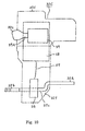
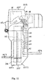
- the thermal electromagnetic tripping unit 32B shown in Fig. 9 is shaped in such a manner that terminal conductors 32a and shunt connection conductors 32b as fixing-side conductors and the trip portion 32c project from the outer structure of the unit.
- the electronic tripping unit 32C shown in Fig. 10 is shaped in such a manner that terminal conductors 32a, shunt connection conductors 32b, and the trip portion 32c project from the outer structure of the unit.
- the earth-leakage tripping unit 32A, the thermal electromagnetic tripping unit 32B, and the electronic tripping unit 32C have the same, hook-like outer shape.
- the outer structures of the tripping units 32A, 32B, and 32C will be described below with reference to Figs. 3-5 by taking the earth-leakage tripping unit 32A as an example.
- the earth-leakage tripping unit 32A is composed of a unit base 32f to be inserted into the unit housing portion 28 and a unit cover 32d that is disposed on the unit base 32f (see Fig. 3).
- the unit cover 32d is composed of an equal-width portion 32d1 having approximately the same width as the unit base 32f in the breaker longitudinal direction and a projected portion 32d2 projecting away from the breaking portion (see Fig. 5), and assumes a hook shape when viewed from the side. Therefore, when the unit 32A is inserted in the unit housing portion 28 and combined with the breaker main body, the projected portion 32d2 is located over the terminal conductors 32a.
- the earth-leakage tripping unit 32A To perform a bimetal tripping operation at the occurrence of an overcurrent, an electromagnetic tripping operation at the occurrence of an overcurrent, and a tripping operation with a leakage detection ZCT, the earth-leakage tripping unit 32A needs to be equipped with elements for performing these three operations.
- a leakage detection ZCT 34 is mainly provided in the internal space of the unit base 32f.
- the major surfaces (i.e., the end faces of a hollow cylinder) of the leakage detection ZCT 34 extend perpendicularly to the longitudinal direction of the circuit breaker.
- An output conductor 34a of the leakage detection ZCT 34 that is connected to a circuit board of an amplification circuit 35 is led out sideways from the leakage detection ZCT 34.
- Each primary conductor 37 consisting of the terminal conductor 32a, an intermediate conductor 37a, and the shunt connection conductor 32b may be a member that is formed by bending a single plate-like conductor. Alternatively, each primary conductor 37 may be formed by joining a plurality of plate-like conductors by welding, screwing, or the like.
- the opening/closing-mechanism-20-side conductors of the primary conductors 37 are called the shunt connection conductors 32b because the circuit breaker being described is of such a type as to use the shunts 8. In general, they are called "movable-contact-side conductors.”
- a projected portion 39 as a top portion of a bimetal 33, a relay trip bar 38, and an electromagnet portion 36 are provided in most of the internal space of the unit cover 32d at a high density.
- the electromagnet portion 36 is disposed at the top end of the bimetal 33 and is composed of an electromagnet, a plunger, a control circuit, and a fixing plate to which they are attached.
- the electromagnet portion 36 usually has a long and narrow shape considering a plunger stroke. Further, the electromagnet portion 36 is required to have a large size because it needs to house a large coil to produce sufficient force to push the relay trip bar 38. Therefore, it is appropriate to accommodate part of the electromagnet portion 36 in the unit cover 32d having the projected portion.
- the circuit board of the amplification circuit 35 for amplifying an electric output signal from the leakage detection ZCT 34 is disposed beside the leakage detection ZCT 34 and is press-fit in and fixed to a rib that is provided on an inner surface of the unit base 32f.
- the inside surface of the circuit board extends parallel with part of the outside circumferential surface of the leakage detection ZCT 34.
- the electromagnet portion 36 that operates on the basis of an output signal of the amplification circuit 35 is provided inside the unit cover 32d.
- the control circuit and part of the fixing plate of the electromagnet portion 36 are provided in a space 32e.
- an overcurrent tripping element more specifically, the bimetal 33
- the bimetal 33 is fixed to one of the primary conductors 37 by squeezing so as to extend approximately parallel with the end faces (i.e., major surfaces) of the leakage detection ZCT 34.
- a fine adjustment threaded portion is provided at the tip of the bimetal 33, and the proj ected portion 39 that is in contact with the relay trip bar 38 is screwed in the threaded portion.
- Each primary conductor 37, the unit base 32 f, a fixing plate 4 6 made of a non-magnetic metal (stainless steel, aluminum, an alloy thereof, or the like), and a bracket-shaped yoke 42 are fastened to each other by tightening a fixing screw 46b.
- An electromagnetic tripping portion is formed by the yoke 42, an armature 43, a spring 45, and the fixing plate 46.
- the armature 43 is a lamination of a plurality of magnetic plates (iron plates) , and the armature 43 itself and its moving plane are approximately parallel with the major surfaces of the leakage detection ZCT 34.
- the armature 43 can rotate on a rotary shaft 43a (a bearing is provided on the fixing plate 46). Normally, the armature 43 is urged counterclockwise (in Fig. 8) on the rotary shaft 43a by the spring 45 that is stretched between a hooking stud 43c of the armature 43 and a hooking stud 46a of the fixing plate 46.
- the armature 43 abuts on a stopper 46c that is provided on the fixing plate 46, thereby its rotation is stopped.
- a tip portion 43b of the armature 43 is connected to a tripping rod 44, which is fixed to the relay trip bar 38 by a fixing screw 38a (see Fig. 6). Since the armature 43 consists of a plurality of magnetic plates, each magnetic plate can be made thin and hole formation and punching on each magnetic plate are facilitated. As a result, the fixing hole of the rotary shaft 43a, the tip portion 43b, the hooking stud 43c, etc. can be formed easily.
- the relay trip bar 38 is rotated clockwise in Fig. 6 and hence is disengaged from the trip portion 32c, whereby the trip portion 32c is rotated counterclockwise in Fig. 6.
- the relay trip bar 38 is rotationally supported on a pin 40 (in Fig. 3, the pin 40 looks as if to be rotationally supported by the unit cover 32d; this is because the unit cover 32d and the unit base 32f have an overlap that extends to below the projected portion 39).
- the relay trip bar 38 is urged counterclockwise (in Figs. 3 and 6) about the pin 40 by a torsion spring (not shown). Part of the relay trip bar 38 is in contact with a stopper (not shown) that is provided on the unit base 32f, whereby the relay trip bar 38 is held at the position of the figures.
- the bimetal 33 (see Fig. 6) is bent rightward and the projected portion 39 at the tip of the bimetal 33 pushes the relay trip bar 38, whereby the relay trip bar 38 is rotated clockwise (in Fig. 6) about the pin 40 and disengaged from the trip portion 32c.
- the trip portion 32c is rotated counterclockwise (in Fig. 6) about the shaft 41 which is the rotation supporting point of the trip portion 32c.
- the trip portion 32c pushes the latch portion 30 (see Fig. 2) and thereby trips the breaker main body.
- an overcurrent exceeds a certain limit (i.e., a current larger than a current that causes a tripping operation of the bimetal 33)
- the yoke 42 around the primary conductor 37 is magnetized and attracts the armature 43 so as to rotate the armature 43 clockwise (in Fig. 8) on the rotary shaft 43a.
- the tripping rod 44 connected to the armature 43 is moved downward (in Fig. 8) and the relay trip bar 38 is rotated clockwise (in Fig. 6) about the pin 40, whereby the breaker main body is tripped in the same manner as in the case of the tripping by the bimetal 33.
- the zero-phase-sequence current is picked up by the leakage detection ZCT 34 and amplified by the amplification circuit 35.
- the plunger of the earth-leakage tripping electromagnet portion 36 pushes the relay trip bar 38, whereby the breaker main body is tripped in the same manner as in the case of the overcurrent tripping operations.
- the thermal electromagnetic tripping unit 32B will be described. Referring to Fig. 9, attention is paid to each combination of a bimetal 50, a yoke 51, and an intermediate conductor 37b between a terminal conductor 32a and a shunt conductor 32b.
- the bimetal 50, the yoke 51, and the intermediate conductor 37b, all of which are provided in a unit base 32f, are squeezed into an integral member by means of rivets 52.
- the yoke 51 has a bracket-shaped cross-section and is disposed in such a manner that the opening of the bracket shape is located on the side opposite to the opening/closing mechanism 20 (i.e., on the side of an armature 53). Since the intermediate conductor 37b need not penetrate through a leakage detection ZCT, it is straight when viewed from above (i.e., in Fig. 1). The same is true of the electronic tripping unit 32C.
- a relay trip bar 38 has an extended portion 38b that extends downward from a pin 40.
- a yoke-confronting portion 53a of the armature 53 is attracted by the yoke 51 and the armature 51 is rotated counterclockwise on a rotary shaft 54.
- a tip portion 53b of the armature 53 touches the extended portion 38b of the relay trip bar 38, whereby the relay trip bar 38 is rotated clockwise about the pin 40.
- the circuit breaker is then tripped in the same manner as described above.
- the armature 53 is normally urged clockwise on the rotary shaft 54 by a spring (not shown).
- the tripping operation by bimetal 50 is the same as that by the bimetal 33 in the earth-leakage tripping unit 32A.
- each intermediate conductor 37c that is located between a terminal conductor 32a and a shunt conductor 32b and provided in a unit base 32f is provided with a current detection CT 56.
- An output conductor 57 of the CT 56 is connected to an amplification circuit 58.
- An electromagnet portion 59 operates on the basis of an output of the amplification circuit 58. If an overcurrent occurs, the electromagnet portion 59 starts to operate, whereby a plunger 59a of the electromagnet portion 59 that has a trip portion 32c at one end is moved leftward andtouchesthelatchportion30 (see Fig. 2). Thecircuitbreaker is thus tripped.
- each of the units 32A, 32B, and 32C can be accommodated in the unit housing portion 28 of the breaker case 1 in a replaceable manner as shown in Figs. 1 and 2.
- the unit cover 32d2 has the extension space 32e that is located over the load-side terminal conductors 32a (see Figs. 2 and 3), the extension space 32c enables accommodation of the earth-leakage tripping electromagnet portion 36 as shown in Fig. 3.
- the earth-leakage tripping electromagnet portion 36 which is conventionally provided on the opening/closing mechanism 20 side of the latch portion 30, is provided on the opposite side of the latch portion 30 to the opening/closing mechanism 20 and inside the outer structure of the tripping unit 32A. Therefore, the electromagnet portion 36 is not exposed to arc gas that may occur between the contacts 3 and 6 at the time of a break and hence is prevented from becoming non-operational after arc extinction.
- the major surfaces of the leakage detection ZCT 34 are set perpendicular to the longitudinal direction of the circuit breaker and the bimetal 33 and the electromagnetic tripping portions (yokes 42 and armatures 43) are provided on the terminal conductor 32a side of the leakage detection ZCT 34. This prevents the electromagnetic tripping portions from being bombarded directly by an arc in the case where the opening/closing mechanism 20 side of the unit base 32f is open.
- the primary conductors 37 be of a division type or have a small-cross-section portion for heating the bimetal 33 efficiently be provided at the position close to an end portion of the bimetal that are on the side of the case of the unit 32A or 32B opposed to the outside, because in this arrangement heat can easily be radiated outside the circuit breaker.
- the metal fixing plates 46 for supporting the respective armatures 43 are located close to the respective bimetal 33. Therefore, the heat radiation is made more easier than in the case where the fixing plates 46 are made of a resin, and the armatures 43 can be fixed reliably while only a small space is occupied.
- the major surfaces of the leakage detection ZCT 34 are set perpendicular to the longitudinal direction of the circuit breaker, and the major surface of the bimetal 33, the plane of the bracket shape of the yoke 42, themajor surfaces of the armature 43, and the moving plane of the armature 43 are set approximately parallel with the major surfaces of the leakage detection ZCT 34. This makes it possible to shorten the earth-leakage tripping unit 32A in the longitudinal direction of the circuit breaker.
- Fig. 11 is a side view of an earth-leakage tripping unit of a circuit breaker according to the second embodiment of the invention.
- Fig. 12 is an explosion view of an outer structure of the earth-leakage tripping unit of Fig. 11.
- Fig. 13 illustrates a relationship between a leakage detection ZCT and amplification circuit in the earth-leakage tripping unit of Fig. 11.
- a bimetal and electromagnetic tripping portions are not shown in Fig. 13.
- the other part of the configuration is the same as in the first embodiment and hence will be omitted.
- the unit base 32f is divided, in the longitudinal direction of the circuit breaker, into two parts, that is, an opening/closing-mechanism-side base 32f1 and a terminal-side base 32f2.
- the primary conductors 37, the bimetal 33, the electromagnetic tripping portions (yokes 42, armatures 43, etc.), the leakage detection ZCT 34, the amplification circuit 35, the electromagnet portion 36, the relay trip bar 38, etc. are attached to the terminal-side base 32f2.
- the opening/closing-mechanism-side base 32f1 is fixed to the terminal-side base 32f2 with screws (not shown), and the unit cover 32d is fixed to the unit base 32f.
- the amplification circuit 35 is disposed beside the leakage detection ZCT 34 in such a manner that its inside surface extends parallel with part of the outside circumferential surface of the leakage detection ZCT 34.
- each of the primary conductors 37 is of a monolithic type, they are attached to the load-side base 32f2 being brought downward (in Fig. 13) together with the leakage detection ZCT 34.
- each of the primary conductors 37 is of a division type, first the leakage detection ZCT 34 is attached to the load-side base 32f2 and then the amplification circuit 35 is brought from the viewer's side toward the deep side (in Fig. 13).
- the amplification circuit 35 can be accommodated in such a manner that its inside periphery extends along part of the outer circumference of the leakage detection ZCT 34. Further, dense mounting is enabled and the airtightness of the outer structure can be increased.
Landscapes
- Breakers (AREA)
Abstract
Description
- The present invention relates to a circuit breaker having unitized automatic tripping devices.
- Among circuit breakers having unitized automatic tripping devices is one that is disclosed in Japanese Patent No. 2, 583, 491. In this circuit breaker, two types of automatic tripping devices, that is, an electronic one and a thermal electromagnetic one, are each unitized and have the same outer shape. A breaker case has a unit housing portion capable of housing each unit.
- Only the electronic automatic tripping unit and the thermal electromagnetic one are prepared for the above circuit breaker so as to be replaceable. However, no earth-leakage detection type automatic tripping unit is available. Therefore, it is necessary to produce a separate circuit breaker having an earth-leakage tripping device. There is another problem that the above automatic tripping units having the same outer shape do not have a sufficient space to accommodate all the components of an earth-leakage tripping mechanism, that is, an overcurrent tripping element, a leakage detection ZCT, an amplification circuit, and an earth-leakage tripping electromagnet portion.
- The present invention has been made to solve the above problems, and an object of the invention is therefore to provide a circuit breaker that makes it possible to substitute and replace also an earth-leakage detection type automatic tripping unit.
- To attain the above obj ect, the invention provides a circuit breaker in which a breaker case is composed of a base and a cover and that is formed by accommodating one of unitized automatic tripping devices in a recess of the base, wherein an electronic automatic tripping unit, a thermal electromagnetic automatic tripping unit, and an earth-leakage detection type automatic tripping unit have outer structures of the same shape from which a trip portion, terminal conductors, and movable-contact-side conductors are exposed; and wherein overcurrent tripping elements, a leakage detection ZCT, an amplification circuit for amplifying an output of the leakage detection ZCT, and an earth-leakage tripping electromagnet portion that operates on the basis of an output of the amplification circuit are accommodated in the outer structure of the earth-leakage detection type automatic tripping unit.
- In the circuit breaker according to the invention, the automatic tripping devices of the respective types are unitized into units having the same outer shape. Therefore, the automatic tripping devices of the respective types including the earth-leakage detection type automatic tripping device can be replaced with one of the other two types of the tripping devices. This provides an advantage that it is not necessary to produce a separate circuit breaker peculiar to an earth-leakage detection type automatic tripping device as in the conventional case; it is sufficient to produce a single type of circuit breaker.
- The other objects and features of this invention will become understood from the following description with reference to the accompanying drawings.
-
- Fig. 1 is a top view of a circuit breaker according to a first embodiment of the present invention;
- Fig. 2 is a somewhat enlarged sectional view taken along line II-II in Fig. 1;
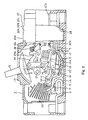
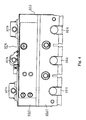
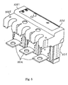
- Figs. 3-5 is a side view, a top view, and a perspective view, respectively, of an earth-leakage tripping unit according to the first embodiment;
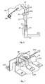
- Fig. 6 shows the internal structure of a an earth-leakage tripping mechanism according to the first embodiment;
- Fig. 7 is a perspective view showing an arrangement of a leakage detection ZCT and primary conductors of the earth-leakage tripping unit according to the first embodiment;
- Fig. 8 is a partially sectional view of an electromagnetic tripping portion of the earth-leakage tripping unit according to the first embodiment;
- Fig. 9 shows an important part of a thermal electromagnetic tripping unit according to the first embodiment;
- Fig. 10 shows an important part of an electronic tripping unit according to the first embodiment;
- Fig. 11 is a side view of an earth-leakage tripping unit of a circuit breaker according to a second embodiment of the invention;
- Fig. 12 shows an outer structure of the earth-leakage tripping unit according to the second embodiment; and
- Fig. 13 illustrates a relationship between a leakage detection ZCT and amplification circuit in the earth-leakage tripping unit according to the second embodiment.
-
- A first embodiment of the present invention will be hereinafter described. Fig. 1 is a top view of a circuit breaker according to the first embodiment of the invention, and shows a state that a tripping unit is removed. The positions of conductors that would proj ect from a tripping unit if the tripping unit were attached are indicated by broken lines.
- As shown in Figs. 1 and 2, a
breaker case 1 made of a synthetic resin is composed of a base 1a and a cover 1b. Fixed contacts 3 are fixed to power-source-sidefixed conductors 2 that are fixed to the base 1a, respectively.Movable contacts 6 that are opposed to the fixed contacts3 and are to come into or go out of contact with the fixed contacts 3 are fixed tomovable elements 7, respectively. Themovable elements 7 are connected, via flexible conductors (shunts) 8, toconnection conductors 9, respectively, to be connected to one ofautomatic tripping units contact arm 10 is divided into two parts, that is, afirst contact arm 10a that holds themovable elements 7 and is linked to an opening/closing mechanism (described later) and a second contact arm 10b that holds themovable elements 7 rotatably by means of afirst pin 11. - The
first contact arm 10a and the second contact arm 10b are rotatably supported by asupport shaft 12 of thecontact arm 10. A crossbar 13 connects thefirst contact arms 10a of the respective poles. Thefirst contact arm 10a is formed with aguide hole 14 extending in the opening/closing direction. The second contact arm 10b is formed with along hole 15 extending in a direction that crosses theguide hole 14. Provided between thefirst pin 11 and asecond pin 16, a pullingspring 17 urges thesecond pin 16 that is engaged with both of theguide hole 14 and thelong hole 15.Apressure spring 18 is providedbetween themovable element 7 and the second contact arm 10b. - A
manipulation handle 19 of the breaker causes, via an opening/closing mechanism 20, themovable element 7 to perform an opening or closing action. The opening/closing mechanism 20 of the breaker is composed of acradle 20a, a top link 20b, a bottom link 20c, etc. Thecradle 20a rotates on arotary shaft 21. The bottom link 20c is provided with alink pin 22 as a link to thefirst contact arm 10a. Thebreaker case 1 is provided with anarc extinction room 23 for extinguishing an arc. - The base 1a is provided with a
unit housing portion 28 that is a recess for housing one of thetripping units indication surface 29 of theunit latch portion 30 that is engaged with thecradle 20a of the opening/closing mechanism 20 is manipulated by a push of atrip portion 32c of theunit type tripping unit 32A (see Fig. 3), the thermalelectromagnetic tripping unit 32B (see Fig. 9) , and theelectronic tripping unit 32C (see Fig. 10) can be replaced with each other because their outer structures have the same shape. - If an overcurrent flows in a state that as shown in Fig. 2 the
unit unit housing portion 28 of the breaker base 1a and is connected to the conductors 9 (ordinary use state), theunit trip portion 32c, whereby thelatch portion 30 is manipulated. Thetrip portion 32c is normally urged counterclockwise about ashaft 41 by a torsion spring 41a (see Figs. 3 and 6). - The earth-
leakage tripping unit 32A shown in Fig. 3 is shaped in such a manner thatterminal conductors 32a andshunt connection conductors 32b as fixing-side conductors and thetrip portion 32c project from the outer structure of the unit (described later in detail). The thermalelectromagnetic tripping unit 32B shown in Fig. 9 is shaped in such a manner thatterminal conductors 32a andshunt connection conductors 32b as fixing-side conductors and thetrip portion 32c project from the outer structure of the unit. Theelectronic tripping unit 32C shown in Fig. 10 is shaped in such a manner thatterminal conductors 32a,shunt connection conductors 32b, and thetrip portion 32c project from the outer structure of the unit. In the side views of Figs. 3, 9, and 10, the earth-leakage tripping unit 32A, the thermalelectromagnetic tripping unit 32B, and theelectronic tripping unit 32C have the same, hook-like outer shape. - The outer structures of the
tripping units leakage tripping unit 32A as an example. The earth-leakage tripping unit 32A is composed of aunit base 32f to be inserted into theunit housing portion 28 and aunit cover 32d that is disposed on theunit base 32f (see Fig. 3). Theunit cover 32d is composed of an equal-width portion 32d1 having approximately the same width as theunit base 32f in the breaker longitudinal direction and a projected portion 32d2 projecting away from the breaking portion (see Fig. 5), and assumes a hook shape when viewed from the side. Therefore, when theunit 32A is inserted in theunit housing portion 28 and combined with the breaker main body, the projected portion 32d2 is located over theterminal conductors 32a. - To perform a bimetal tripping operation at the occurrence of an overcurrent, an electromagnetic tripping operation at the occurrence of an overcurrent, and a tripping operation with a leakage detection ZCT, the earth-
leakage tripping unit 32A needs to be equipped with elements for performing these three operations. - As shown in Figs. 3 and 7, of the internal space of outer structure formed by the
unit base 32f and theunit cover 32d of the earth-leakage tripping unit 32A, aleakage detection ZCT 34 is mainly provided in the internal space of theunit base 32f. The portions of the three-phaseprimary conductors 37 between theterminal conductors 32a and theshunt connection conductors 32b penetrate through the cavity of theleakage detection ZCT 34. The major surfaces (i.e., the end faces of a hollow cylinder) of theleakage detection ZCT 34 extend perpendicularly to the longitudinal direction of the circuit breaker. An output conductor 34a of theleakage detection ZCT 34 that is connected to a circuit board of anamplification circuit 35 is led out sideways from theleakage detection ZCT 34. - Each
primary conductor 37 consisting of theterminal conductor 32a, anintermediate conductor 37a, and theshunt connection conductor 32b may be a member that is formed by bending a single plate-like conductor. Alternatively, eachprimary conductor 37 may be formed by joining a plurality of plate-like conductors by welding, screwing, or the like. As for the term "shunt connection conductors," the opening/closing-mechanism-20-side conductors of theprimary conductors 37 are called theshunt connection conductors 32b because the circuit breaker being described is of such a type as to use theshunts 8. In general, they are called "movable-contact-side conductors." - As shown in Figs. 3 and 7, of the internal space of outer structure formed by the
unit base 32f and theunit cover 32d of the earth-leakage tripping unit 32A, a projectedportion 39 as a top portion of a bimetal 33, arelay trip bar 38, and anelectromagnet portion 36 are provided in most of the internal space of theunit cover 32d at a high density. Theelectromagnet portion 36 is disposed at the top end of the bimetal 33 and is composed of an electromagnet, a plunger, a control circuit, and a fixing plate to which they are attached. Theelectromagnet portion 36 usually has a long and narrow shape considering a plunger stroke. Further, theelectromagnet portion 36 is required to have a large size because it needs to house a large coil to produce sufficient force to push therelay trip bar 38. Therefore, it is appropriate to accommodate part of theelectromagnet portion 36 in theunit cover 32d having the projected portion. - As shown in Fig. 3, the circuit board of the
amplification circuit 35 for amplifying an electric output signal from theleakage detection ZCT 34 is disposed beside theleakage detection ZCT 34 and is press-fit in and fixed to a rib that is provided on an inner surface of theunit base 32f. The inside surface of the circuit board extends parallel with part of the outside circumferential surface of theleakage detection ZCT 34. As described above, theelectromagnet portion 36 that operates on the basis of an output signal of theamplification circuit 35 is provided inside theunit cover 32d. The control circuit and part of the fixing plate of theelectromagnet portion 36 are provided in aspace 32e. - As shown in Figs. 3, 6, and 8, an overcurrent tripping element, more specifically, the bimetal 33, is fixed to one of the
primary conductors 37 by squeezing so as to extend approximately parallel with the end faces (i.e., major surfaces) of theleakage detection ZCT 34. A fine adjustment threaded portion is provided at the tip of the bimetal 33, and the proj ectedportion 39 that is in contact with therelay trip bar 38 is screwed in the threaded portion. Eachprimary conductor 37, theunit base 32 f, a fixing plate 4 6 made of a non-magnetic metal (stainless steel, aluminum, an alloy thereof, or the like), and a bracket-shapedyoke 42 are fastened to each other by tightening a fixing screw 46b. An electromagnetic tripping portion is formed by theyoke 42, anarmature 43, aspring 45, and the fixingplate 46. - The
armature 43 is a lamination of a plurality of magnetic plates (iron plates) , and thearmature 43 itself and its moving plane are approximately parallel with the major surfaces of theleakage detection ZCT 34. Thearmature 43 can rotate on arotary shaft 43a (a bearing is provided on the fixing plate 46). Normally, thearmature 43 is urged counterclockwise (in Fig. 8) on therotary shaft 43a by thespring 45 that is stretched between a hookingstud 43c of thearmature 43 and a hooking stud 46a of the fixingplate 46. Thearmature 43 abuts on astopper 46c that is provided on the fixingplate 46, thereby its rotation is stopped. - A tip portion 43b of the
armature 43 is connected to a trippingrod 44, which is fixed to therelay trip bar 38 by a fixingscrew 38a (see Fig. 6). Since thearmature 43 consists of a plurality of magnetic plates, each magnetic plate can be made thin and hole formation and punching on each magnetic plate are facilitated. As a result, the fixing hole of therotary shaft 43a, the tip portion 43b, the hookingstud 43c, etc. can be formed easily. - If a bimetal 33, the tripping
rod 44, or the plunger of theelectromagnet portion 36 exerts force on therelay trip bar 38, therelay trip bar 38 is rotated clockwise in Fig. 6 and hence is disengaged from thetrip portion 32c, whereby thetrip portion 32c is rotated counterclockwise in Fig. 6. Therelay trip bar 38 is rotationally supported on a pin 40 (in Fig. 3, thepin 40 looks as if to be rotationally supported by theunit cover 32d; this is because theunit cover 32d and theunit base 32f have an overlap that extends to below the projected portion 39). Normally, therelay trip bar 38 is urged counterclockwise (in Figs. 3 and 6) about thepin 40 by a torsion spring (not shown). Part of therelay trip bar 38 is in contact with a stopper (not shown) that is provided on theunit base 32f, whereby therelay trip bar 38 is held at the position of the figures. - Next, the tripping operation of the earth-leakage tripping unit will be described with reference to Figs. 3, 6, and 8. The tripping operations with overcurrent detection, that is, the tripping operation of the bimetal 33 and the electromagnetic tripping operation, will be described first, and then the tripping operation with leakage detection will be described. (Tripping by the bimetal at the occurrence of overcurrent)
- If an overcurrent flows through a
primary conductor 37, the bimetal 33 (see Fig. 6) is bent rightward and the projectedportion 39 at the tip of the bimetal 33 pushes therelay trip bar 38, whereby therelay trip bar 38 is rotated clockwise (in Fig. 6) about thepin 40 and disengaged from thetrip portion 32c. As a result, thetrip portion 32c is rotated counterclockwise (in Fig. 6) about theshaft 41 which is the rotation supporting point of thetrip portion 32c. Thetrip portion 32c pushes the latch portion 30 (see Fig. 2) and thereby trips the breaker main body. - If an overcurrent exceeds a certain limit (i.e., a current larger than a current that causes a tripping operation of the bimetal 33), the
yoke 42 around theprimary conductor 37 is magnetized and attracts thearmature 43 so as to rotate thearmature 43 clockwise (in Fig. 8) on therotary shaft 43a. As a result, the trippingrod 44 connected to thearmature 43 is moved downward (in Fig. 8) and therelay trip bar 38 is rotated clockwise (in Fig. 6) about thepin 40, whereby the breaker main body is tripped in the same manner as in the case of the tripping by the bimetal 33. - If a leakage occurs in a
primary conductor 37 on the load side of theleakage detection ZCT 34 to cause a zero-phase-sequence current, the zero-phase-sequence current is picked up by theleakage detection ZCT 34 and amplified by theamplification circuit 35. As a result, the plunger of the earth-leakage trippingelectromagnet portion 36 pushes therelay trip bar 38, whereby the breaker main body is tripped in the same manner as in the case of the overcurrent tripping operations. - Next, the thermal electromagnetic tripping
unit 32B will be described. Referring to Fig. 9, attention is paid to each combination of a bimetal 50, ayoke 51, and anintermediate conductor 37b between aterminal conductor 32a and ashunt conductor 32b. The bimetal 50, theyoke 51, and theintermediate conductor 37b, all of which are provided in aunit base 32f, are squeezed into an integral member by means ofrivets 52. Theyoke 51 has a bracket-shaped cross-section and is disposed in such a manner that the opening of the bracket shape is located on the side opposite to the opening/closing mechanism 20 (i.e., on the side of an armature 53). Since theintermediate conductor 37b need not penetrate through a leakage detection ZCT, it is straight when viewed from above (i.e., in Fig. 1). The same is true of the electronic trippingunit 32C. - A
relay trip bar 38 has an extended portion 38b that extends downward from apin 40. In an electromagnetic tripping operation involving thearmature 53, a yoke-confrontingportion 53a of thearmature 53 is attracted by theyoke 51 and thearmature 51 is rotated counterclockwise on arotary shaft 54. As a result, a tip portion 53b of thearmature 53 touches the extended portion 38b of therelay trip bar 38, whereby therelay trip bar 38 is rotated clockwise about thepin 40. The circuit breaker is then tripped in the same manner as described above. Thearmature 53 is normally urged clockwise on therotary shaft 54 by a spring (not shown). The tripping operation bybimetal 50 is the same as that by the bimetal 33 in the earth-leakage tripping unit 32A. - Next, the electronic tripping
unit 32C will be described. As shown in Fig. 10, eachintermediate conductor 37c that is located between aterminal conductor 32a and ashunt conductor 32b and provided in aunit base 32f is provided with acurrent detection CT 56. Anoutput conductor 57 of theCT 56 is connected to anamplification circuit 58. Anelectromagnet portion 59 operates on the basis of an output of theamplification circuit 58. If an overcurrent occurs, theelectromagnet portion 59 starts to operate, whereby aplunger 59a of theelectromagnet portion 59 that has atrip portion 32c at one end is moved leftward andtouchesthelatchportion30 (see Fig. 2). Thecircuitbreaker is thus tripped. - Since, as described above, the earth-
leakage tripping unit 32A, the thermal electromagnetic trippingunit 32B, and the electronic trippingunit 32C have the same outer shape (see Figs. 3, 9, and 10), each of theunits unit housing portion 28 of thebreaker case 1 in a replaceable manner as shown in Figs. 1 and 2. - Since the unit cover 32d2 has the
extension space 32e that is located over the load-side terminal conductors 32a (see Figs. 2 and 3), theextension space 32c enables accommodation of the earth-leakage trippingelectromagnet portion 36 as shown in Fig. 3. - The earth-leakage tripping
electromagnet portion 36, which is conventionally provided on the opening/closing mechanism 20 side of thelatch portion 30, is provided on the opposite side of thelatch portion 30 to the opening/closing mechanism 20 and inside the outer structure of the trippingunit 32A. Therefore, theelectromagnet portion 36 is not exposed to arc gas that may occur between thecontacts 3 and 6 at the time of a break and hence is prevented from becoming non-operational after arc extinction. - The major surfaces of the
leakage detection ZCT 34 are set perpendicular to the longitudinal direction of the circuit breaker and the bimetal 33 and the electromagnetic tripping portions (yokes 42 and armatures 43) are provided on theterminal conductor 32a side of theleakage detection ZCT 34. This prevents the electromagnetic tripping portions from being bombarded directly by an arc in the case where the opening/closing mechanism 20 side of theunit base 32f is open. - It is preferable that the
primary conductors 37 be of a division type or have a small-cross-section portion for heating the bimetal 33 efficiently be provided at the position close to an end portion of the bimetal that are on the side of the case of theunit metal fixing plates 46 for supporting therespective armatures 43 are located close to therespective bimetal 33. Therefore, the heat radiation is made more easier than in the case where the fixingplates 46 are made of a resin, and thearmatures 43 can be fixed reliably while only a small space is occupied. - The major surfaces of the
leakage detection ZCT 34 are set perpendicular to the longitudinal direction of the circuit breaker, and the major surface of the bimetal 33, the plane of the bracket shape of theyoke 42, themajor surfaces of thearmature 43, and the moving plane of thearmature 43 are set approximately parallel with the major surfaces of theleakage detection ZCT 34. This makes it possible to shorten the earth-leakage tripping unit 32A in the longitudinal direction of the circuit breaker. - A second embodiment of the invention will be hereinafter described.
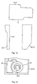
- Fig. 11 is a side view of an earth-leakage tripping unit of a circuit breaker according to the second embodiment of the invention. Fig. 12 is an explosion view of an outer structure of the earth-leakage tripping unit of Fig. 11. Fig. 13 illustrates a relationship between a leakage detection ZCT and amplification circuit in the earth-leakage tripping unit of Fig. 11. To facilitate understanding, a bimetal and electromagnetic tripping portions are not shown in Fig. 13. The other part of the configuration is the same as in the first embodiment and hence will be omitted.
- As shown in Figs. 11 and 12, the
unit base 32f is divided, in the longitudinal direction of the circuit breaker, into two parts, that is, an opening/closing-mechanism-side base 32f1 and a terminal-side base 32f2. To assemble the earth-leakage tripping unit 32A, theprimary conductors 37, the bimetal 33, the electromagnetic tripping portions (yokes 42,armatures 43, etc.), theleakage detection ZCT 34, theamplification circuit 35, theelectromagnet portion 36, therelay trip bar 38, etc. are attached to the terminal-side base 32f2. Then, the opening/closing-mechanism-side base 32f1 is fixed to the terminal-side base 32f2 with screws (not shown), and theunit cover 32d is fixed to theunit base 32f. - In the second embodiment, the
amplification circuit 35 is disposed beside theleakage detection ZCT 34 in such a manner that its inside surface extends parallel with part of the outside circumferential surface of theleakage detection ZCT 34. Where each of theprimary conductors 37 is of a monolithic type, they are attached to the load-side base 32f2 being brought downward (in Fig. 13) together with theleakage detection ZCT 34. Where each of theprimary conductors 37 is of a division type, first theleakage detection ZCT 34 is attached to the load-side base 32f2 and then theamplification circuit 35 is brought from the viewer's side toward the deep side (in Fig. 13). - As described above, since the outer structure of the earth-
leakage tripping unit 32A is composed of three members, theamplification circuit 35 can be accommodated in such a manner that its inside periphery extends along part of the outer circumference of theleakage detection ZCT 34. Further, dense mounting is enabled and the airtightness of the outer structure can be increased.
Claims (8)
- A circuit breaker in which a breaker case (1) is composed of a base (1a) and a cover (1b) and that is formed by accommodating one of unitized automatic tripping devices (32A,32B and 32C) in a unit housing portion (28) of the base (1a), wherein;
the automatic tripping devices include an electronic automatic tripping unit (32C), a thermal electromagnetic automatic tripping unit (32B), and an earth-leakage detection type automatic tripping unit (32A) having outer structures of the same shape from which a trip portion (32c), terminal conductors (32a), andmovable-contact-side conductors (32b) are exposed; and
an overcurrent tripping element (33) , a leakage detection ZCT (34), an amplification circuit (35) for amplifying an output of the leakage detection ZCT (34), and an earth-leakage tripping electromagnetportion (36) thatoperatesonthebasisofanoutput of the amplification circuit (35) are accommodated in the outer structure of the earth-leakage detection type automatic tripping unit (32A). - The circuit breaker according to claim 1, wherein the outer structure of each of the automatic tripping units (32A, 32B and 32C) is formed by a unit base (32f) and a unit cover (32d) that are a bottom portion and a top portion of the outer structure, respectively, and the unit cover (32d) projects from the unit base (32f) so as to be located over portions of the terminal conductors (32a) that are exposed from the unit base (32f).
- The circuit breaker according to claim 1, wherein the outer structure of each of the automatic tripping units (32A, 32B and 32C) is formed by a unit base (32f) that is to be inserted in the unit housing portion (28) of the base (1a) and a unit cover (32d) that is located above the unit base (32f) and projects from the unit base (32f) in such a direction as to go away from an opening/closing mechanism of the circuit breaker; and in the earth-leakage detection type automatic tripping unit (32A), a projected portion of the unit cover (32d) houses part of the earth-leakage tripping electromagnet portion (36).
- The circuit breaker according to claim 1, wherein in the outer structure of the earth-leakage detection type automatic tripping unit (32A), the leakage detection ZCT (34) is disposed on a side closer to an opening/closing mechanism of the circuit breaker and overcurrent tripping portions are disposed on an opposite side of the leakage detection ZCT (34) to the opening/closing mechanism.
- The circuit breaker according to claim 1, wherein in the outer structure of the earth-leakage detection type automatic tripping unit (32A), the leakage detection ZCT (34) is disposed in such a manner that its major surfaces are perpendicular to a longitudinal direction of the terminal conductors (32a), overcurrent tripping bimetal (33) are disposed in such a manner as to extend parallel with the major surfaces of the leakage detection ZCT (34) in a depth direction of the unit housing portion (28), and a yokes (42) of electromagnetic tripping portions and a moving plane of an armature (43) to be attracted by the respective yoke (42) are disposed parallel with the major surfaces of the leakage detection ZCT (34).
- The circuit breaker according to claim 5, wherein a fixing plate (46) made of a non-magnetic metal by or to which the armature (43) or the yoke (42) of the electromagnetic tripping portions is supported or fixed, respectively, is opposed to an outer surface of the outer structure.
- The circuit breaker according to claim 1, wherein the outer structure of each of the automatic tripping units (32A, 32B and 32C) is formed by a unit base (32f) that is to be inserted in the unit housing portion (28) of the base (1a) and a unit cover (32d) that is located above the unit base (32f), and the unit base (32f) is formed by combining an opening/closing-mechanism-side unit base (32f1) that is closer to an opening/closing mechanism of the circuit breaker and a terminal-side unit base (32f2) that is farther from the opening/closing mechanism.
- The circuit breaker according to claim 7, wherein the amplification circuit is formed on a circuit board and the circuit board is provided so as to extend along part of an outside circumference of the leakage detection ZCT (34) in a plane parallel with major surfaces of the leakage detection ZCT (34).
Applications Claiming Priority (2)
| Application Number | Priority Date | Filing Date | Title |
|---|---|---|---|
| JP2002329988A JP4090850B2 (en) | 2002-11-13 | 2002-11-13 | Circuit breaker |
| JP2002329988 | 2002-11-13 |
Publications (2)
| Publication Number | Publication Date |
|---|---|
| EP1420431A1 true EP1420431A1 (en) | 2004-05-19 |
| EP1420431B1 EP1420431B1 (en) | 2006-09-27 |
Family
ID=32171390
Family Applications (1)
| Application Number | Title | Priority Date | Filing Date |
|---|---|---|---|
| EP20030013394 Expired - Lifetime EP1420431B1 (en) | 2002-11-13 | 2003-06-18 | Circuit breaker |
Country Status (4)
| Country | Link |
|---|---|
| EP (1) | EP1420431B1 (en) |
| JP (1) | JP4090850B2 (en) |
| CN (1) | CN1255834C (en) |
| DE (1) | DE60308622T2 (en) |
Cited By (6)
| Publication number | Priority date | Publication date | Assignee | Title |
|---|---|---|---|---|
| FR2899723A1 (en) * | 2006-04-07 | 2007-10-12 | Fuji Elec Fa Components & Sys | CIRCUIT BREAKER EARTH. |
| US7378761B2 (en) | 2002-08-02 | 2008-05-27 | Protectelec Pty Ltd | Control circuit and a method for electrically connecting a load to a power source |
| WO2009082358A1 (en) * | 2007-12-24 | 2009-07-02 | Eti Elektroelement D.D. | Electric automatic switc |
| CN101908447A (en) * | 2009-06-08 | 2010-12-08 | 三菱电机株式会社 | circuit breaker |
| EP2816582A1 (en) * | 2013-06-20 | 2014-12-24 | Schneider Electric Industries SAS | Trigger and method for manufacturing such a trigger |
| CN110660622A (en) * | 2018-06-29 | 2020-01-07 | 宁波江北思洞工业设计有限公司 | Moulded case circuit breaker with safety protection structure |
Families Citing this family (4)
| Publication number | Priority date | Publication date | Assignee | Title |
|---|---|---|---|---|
| KR100596357B1 (en) * | 2004-09-09 | 2006-07-03 | 동아전기공업 주식회사 | Leakage Current Detection Device |
| JP6157390B2 (en) * | 2014-03-20 | 2017-07-05 | 三菱電機株式会社 | Earth leakage breaker |
| CN103996575A (en) * | 2014-05-09 | 2014-08-20 | 安庆天瑞新材料科技股份有限公司 | Thermomagnetic breaker capable of current detection and communication |
| WO2019064453A1 (en) * | 2017-09-28 | 2019-04-04 | 三菱電機株式会社 | Electronic circuit breaker |
Citations (5)
| Publication number | Priority date | Publication date | Assignee | Title |
|---|---|---|---|---|
| EP0255955A2 (en) * | 1986-08-07 | 1988-02-17 | Mitsubishi Denki Kabushiki Kaisha | Circuit interrupter |
| WO1991013454A1 (en) * | 1990-02-23 | 1991-09-05 | Square D Company | A circuit breaker |
| US5841616A (en) * | 1994-07-23 | 1998-11-24 | Delta Circuit Protection & Controls Limited | Module for use with a miniature circuit breaker |
| EP0962952A1 (en) * | 1998-06-04 | 1999-12-08 | Schneider Electric Industries SA | Dispositif de coupure électrique comprenant un dispositif de déclenchement différentiel et disjoncteur comprenant un tel dispositif |
| US6137386A (en) * | 1999-08-18 | 2000-10-24 | Eaton Corporation | Circuit breaker with trip unit mounted tripping plunger and latch therefore |
-
2002
- 2002-11-13 JP JP2002329988A patent/JP4090850B2/en not_active Expired - Fee Related
-
2003
- 2003-06-18 EP EP20030013394 patent/EP1420431B1/en not_active Expired - Lifetime
- 2003-06-18 DE DE2003608622 patent/DE60308622T2/en not_active Expired - Lifetime
- 2003-07-14 CN CN 03145899 patent/CN1255834C/en not_active Expired - Fee Related
Patent Citations (5)
| Publication number | Priority date | Publication date | Assignee | Title |
|---|---|---|---|---|
| EP0255955A2 (en) * | 1986-08-07 | 1988-02-17 | Mitsubishi Denki Kabushiki Kaisha | Circuit interrupter |
| WO1991013454A1 (en) * | 1990-02-23 | 1991-09-05 | Square D Company | A circuit breaker |
| US5841616A (en) * | 1994-07-23 | 1998-11-24 | Delta Circuit Protection & Controls Limited | Module for use with a miniature circuit breaker |
| EP0962952A1 (en) * | 1998-06-04 | 1999-12-08 | Schneider Electric Industries SA | Dispositif de coupure électrique comprenant un dispositif de déclenchement différentiel et disjoncteur comprenant un tel dispositif |
| US6137386A (en) * | 1999-08-18 | 2000-10-24 | Eaton Corporation | Circuit breaker with trip unit mounted tripping plunger and latch therefore |
Cited By (11)
| Publication number | Priority date | Publication date | Assignee | Title |
|---|---|---|---|---|
| US7378761B2 (en) | 2002-08-02 | 2008-05-27 | Protectelec Pty Ltd | Control circuit and a method for electrically connecting a load to a power source |
| FR2899723A1 (en) * | 2006-04-07 | 2007-10-12 | Fuji Elec Fa Components & Sys | CIRCUIT BREAKER EARTH. |
| WO2009082358A1 (en) * | 2007-12-24 | 2009-07-02 | Eti Elektroelement D.D. | Electric automatic switc |
| CN101908447A (en) * | 2009-06-08 | 2010-12-08 | 三菱电机株式会社 | circuit breaker |
| CN101908447B (en) * | 2009-06-08 | 2013-09-18 | 三菱电机株式会社 | Circuit breaker |
| EP2816582A1 (en) * | 2013-06-20 | 2014-12-24 | Schneider Electric Industries SAS | Trigger and method for manufacturing such a trigger |
| FR3007573A1 (en) * | 2013-06-20 | 2014-12-26 | Schneider Electric Ind Sas | TRIGGER AND METHOD FOR MANUFACTURING SUCH TRIGGER |
| US9202655B2 (en) | 2013-06-20 | 2015-12-01 | Schneider Electric Industries Sas | Trip unit and method for producing one such trip device |
| RU2662733C2 (en) * | 2013-06-20 | 2018-07-30 | Шнейдер Электрик Эндюстри Сас | Trip unit and method for producing such trip unit |
| US10096436B2 (en) | 2013-06-20 | 2018-10-09 | Schneider Electric Industries Sas | Method for producing a trip unit |
| CN110660622A (en) * | 2018-06-29 | 2020-01-07 | 宁波江北思洞工业设计有限公司 | Moulded case circuit breaker with safety protection structure |
Also Published As
| Publication number | Publication date |
|---|---|
| EP1420431B1 (en) | 2006-09-27 |
| JP4090850B2 (en) | 2008-05-28 |
| CN1255834C (en) | 2006-05-10 |
| DE60308622D1 (en) | 2006-11-09 |
| JP2004165022A (en) | 2004-06-10 |
| DE60308622T2 (en) | 2007-08-09 |
| CN1501417A (en) | 2004-06-02 |
Similar Documents
| Publication | Publication Date | Title |
|---|---|---|
| US7986203B2 (en) | Multi-pole armature interlock for circuit breakers | |
| EP1126490B1 (en) | Circuit breaker with latch and toggle mechanism operating in perpendicular planes | |
| US8159318B2 (en) | Electromagnet assembly directly driving latch of an electronic circuit breaker | |
| KR100462657B1 (en) | Circuit breaker | |
| EP1420431B1 (en) | Circuit breaker | |
| CA2899773C (en) | Bimetal and magnetic armature providing an arc splatter resistant offset therebetween, and circuit breaker including the same | |
| AU777311B2 (en) | Circuit breaker with bypass conductor commutating current out of the bimetal during short circuit interruption and method of commutating current out of bimetal | |
| EP1126492B1 (en) | Circuit breaker with instantaneous trip provided by main conductor routed through magnetic circuit of electronic trip motor | |
| US20030090848A1 (en) | Circuit interrupter employing a mechanism to open a power circuit in response to a resistor body burning open | |
| US20040150496A1 (en) | Self-contained mechanism on a frame | |
| US20040150497A1 (en) | Non-conductive barrier for separating a circuit breaker trip spring and cradle | |
| CA2425346C (en) | Circuit breaker with bypass for redirecting high transient current and associated method | |
| US5886600A (en) | Modular thermal magnetic trip unit for rapid circuit interruption | |
| JP2595628Y2 (en) | Earth leakage breaker | |
| JPH03233824A (en) | Leakage breaker | |
| AU2002212566A1 (en) | Circuit breaker with bypass for redirecting high transient current and associated method | |
| JPH0243083Y2 (en) | ||
| JPH0215308Y2 (en) | ||
| JP3226319B2 (en) | Remote control circuit breaker | |
| JPH0440821B2 (en) | ||
| JPH02109231A (en) | Remote handling type circuit breaker | |
| JPH10223119A (en) | Circuit breaker | |
| JPH1154019A (en) | Circuit breaker |
Legal Events
| Date | Code | Title | Description |
|---|---|---|---|
| PUAI | Public reference made under article 153(3) epc to a published international application that has entered the european phase |
Free format text: ORIGINAL CODE: 0009012 |
|
| AK | Designated contracting states |
Kind code of ref document: A1 Designated state(s): AT BE BG CH CY CZ DE DK EE ES FI FR GB GR HU IE IT LI LU MC NL PT RO SE SI SK TR |
|
| AX | Request for extension of the european patent |
Extension state: AL LT LV MK |
|
| 17P | Request for examination filed |
Effective date: 20040629 |
|
| AKX | Designation fees paid |
Designated state(s): DE FR |
|
| GRAP | Despatch of communication of intention to grant a patent |
Free format text: ORIGINAL CODE: EPIDOSNIGR1 |
|
| RAP1 | Party data changed (applicant data changed or rights of an application transferred) |
Owner name: MITSUBISHI DENKI KABUSHIKI KAISHA |
|
| RIN1 | Information on inventor provided before grant (corrected) |
Inventor name: KAWAKAMI, KANEHIRO Inventor name: YOSHIHARA, IKUHIRO Inventor name: HOSOGAI, SETSUO |
|
| GRAS | Grant fee paid |
Free format text: ORIGINAL CODE: EPIDOSNIGR3 |
|
| GRAA | (expected) grant |
Free format text: ORIGINAL CODE: 0009210 |
|
| AK | Designated contracting states |
Kind code of ref document: B1 Designated state(s): DE FR |
|
| REF | Corresponds to: |
Ref document number: 60308622 Country of ref document: DE Date of ref document: 20061109 Kind code of ref document: P |
|
| ET | Fr: translation filed | ||
| PLBE | No opposition filed within time limit |
Free format text: ORIGINAL CODE: 0009261 |
|
| STAA | Information on the status of an ep patent application or granted ep patent |
Free format text: STATUS: NO OPPOSITION FILED WITHIN TIME LIMIT |
|
| 26N | No opposition filed |
Effective date: 20070628 |
|
| REG | Reference to a national code |
Ref country code: DE Ref legal event code: R084 Ref document number: 60308622 Country of ref document: DE Effective date: 20110704 Ref country code: DE Ref legal event code: R084 Ref document number: 60308622 Country of ref document: DE Effective date: 20110506 |
|
| REG | Reference to a national code |
Ref country code: FR Ref legal event code: PLFP Year of fee payment: 14 |
|
| REG | Reference to a national code |
Ref country code: FR Ref legal event code: PLFP Year of fee payment: 15 |
|
| REG | Reference to a national code |
Ref country code: FR Ref legal event code: PLFP Year of fee payment: 16 |
|
| PGFP | Annual fee paid to national office [announced via postgrant information from national office to epo] |
Ref country code: DE Payment date: 20190604 Year of fee payment: 17 |
|
| PGFP | Annual fee paid to national office [announced via postgrant information from national office to epo] |
Ref country code: FR Payment date: 20190510 Year of fee payment: 17 |
|
| REG | Reference to a national code |
Ref country code: DE Ref legal event code: R119 Ref document number: 60308622 Country of ref document: DE |
|
| PG25 | Lapsed in a contracting state [announced via postgrant information from national office to epo] |
Ref country code: FR Free format text: LAPSE BECAUSE OF NON-PAYMENT OF DUE FEES Effective date: 20200630 |
|
| PG25 | Lapsed in a contracting state [announced via postgrant information from national office to epo] |
Ref country code: DE Free format text: LAPSE BECAUSE OF NON-PAYMENT OF DUE FEES Effective date: 20210101 |