EP1420262A1 - Procédé et système de détection d'au moins une défaillance d'au moins un interrupteur - Google Patents
Procédé et système de détection d'au moins une défaillance d'au moins un interrupteur Download PDFInfo
- Publication number
- EP1420262A1 EP1420262A1 EP03356173A EP03356173A EP1420262A1 EP 1420262 A1 EP1420262 A1 EP 1420262A1 EP 03356173 A EP03356173 A EP 03356173A EP 03356173 A EP03356173 A EP 03356173A EP 1420262 A1 EP1420262 A1 EP 1420262A1
- Authority
- EP
- European Patent Office
- Prior art keywords
- switch
- electrical circuit
- switches
- converter
- current
- Prior art date
- Legal status (The legal status is an assumption and is not a legal conclusion. Google has not performed a legal analysis and makes no representation as to the accuracy of the status listed.)
- Granted
Links
- 238000000034 method Methods 0.000 title claims description 46
- 238000004804 winding Methods 0.000 claims description 41
- 238000012360 testing method Methods 0.000 claims description 12
- 238000004458 analytical method Methods 0.000 claims description 8
- 238000001514 detection method Methods 0.000 abstract description 13
- 239000004020 conductor Substances 0.000 description 24
- 230000009466 transformation Effects 0.000 description 6
- 230000002457 bidirectional effect Effects 0.000 description 4
- 238000010586 diagram Methods 0.000 description 4
- 235000021183 entrée Nutrition 0.000 description 3
- 230000000903 blocking effect Effects 0.000 description 2
- 238000002955 isolation Methods 0.000 description 2
- 230000006978 adaptation Effects 0.000 description 1
- 210000004027 cell Anatomy 0.000 description 1
- 230000005669 field effect Effects 0.000 description 1
- 238000004519 manufacturing process Methods 0.000 description 1
- 230000002441 reversible effect Effects 0.000 description 1
- 238000010998 test method Methods 0.000 description 1
Images


Classifications
-
- H—ELECTRICITY
- H02—GENERATION; CONVERSION OR DISTRIBUTION OF ELECTRIC POWER
- H02M—APPARATUS FOR CONVERSION BETWEEN AC AND AC, BETWEEN AC AND DC, OR BETWEEN DC AND DC, AND FOR USE WITH MAINS OR SIMILAR POWER SUPPLY SYSTEMS; CONVERSION OF DC OR AC INPUT POWER INTO SURGE OUTPUT POWER; CONTROL OR REGULATION THEREOF
- H02M3/00—Conversion of DC power input into DC power output
- H02M3/22—Conversion of DC power input into DC power output with intermediate conversion into AC
- H02M3/24—Conversion of DC power input into DC power output with intermediate conversion into AC by static converters
- H02M3/28—Conversion of DC power input into DC power output with intermediate conversion into AC by static converters using discharge tubes with control electrode or semiconductor devices with control electrode to produce the intermediate AC
- H02M3/325—Conversion of DC power input into DC power output with intermediate conversion into AC by static converters using discharge tubes with control electrode or semiconductor devices with control electrode to produce the intermediate AC using devices of a triode or a transistor type requiring continuous application of a control signal
- H02M3/335—Conversion of DC power input into DC power output with intermediate conversion into AC by static converters using discharge tubes with control electrode or semiconductor devices with control electrode to produce the intermediate AC using devices of a triode or a transistor type requiring continuous application of a control signal using semiconductor devices only
- H02M3/337—Conversion of DC power input into DC power output with intermediate conversion into AC by static converters using discharge tubes with control electrode or semiconductor devices with control electrode to produce the intermediate AC using devices of a triode or a transistor type requiring continuous application of a control signal using semiconductor devices only in push-pull configuration
- H02M3/3376—Conversion of DC power input into DC power output with intermediate conversion into AC by static converters using discharge tubes with control electrode or semiconductor devices with control electrode to produce the intermediate AC using devices of a triode or a transistor type requiring continuous application of a control signal using semiconductor devices only in push-pull configuration with automatic control of output voltage or current
-
- G—PHYSICS
- G01—MEASURING; TESTING
- G01R—MEASURING ELECTRIC VARIABLES; MEASURING MAGNETIC VARIABLES
- G01R31/00—Arrangements for testing electric properties; Arrangements for locating electric faults; Arrangements for electrical testing characterised by what is being tested not provided for elsewhere
- G01R31/26—Testing of individual semiconductor devices
- G01R31/27—Testing of devices without physical removal from the circuit of which they form part, e.g. compensating for effects surrounding elements
-
- G—PHYSICS
- G01—MEASURING; TESTING
- G01R—MEASURING ELECTRIC VARIABLES; MEASURING MAGNETIC VARIABLES
- G01R31/00—Arrangements for testing electric properties; Arrangements for locating electric faults; Arrangements for electrical testing characterised by what is being tested not provided for elsewhere
- G01R31/327—Testing of circuit interrupters, switches or circuit-breakers
- G01R31/3271—Testing of circuit interrupters, switches or circuit-breakers of high voltage or medium voltage devices
- G01R31/3275—Fault detection or status indication
-
- G—PHYSICS
- G01—MEASURING; TESTING
- G01R—MEASURING ELECTRIC VARIABLES; MEASURING MAGNETIC VARIABLES
- G01R31/00—Arrangements for testing electric properties; Arrangements for locating electric faults; Arrangements for electrical testing characterised by what is being tested not provided for elsewhere
- G01R31/40—Testing power supplies
- G01R31/42—AC power supplies
-
- H—ELECTRICITY
- H02—GENERATION; CONVERSION OR DISTRIBUTION OF ELECTRIC POWER
- H02M—APPARATUS FOR CONVERSION BETWEEN AC AND AC, BETWEEN AC AND DC, OR BETWEEN DC AND DC, AND FOR USE WITH MAINS OR SIMILAR POWER SUPPLY SYSTEMS; CONVERSION OF DC OR AC INPUT POWER INTO SURGE OUTPUT POWER; CONTROL OR REGULATION THEREOF
- H02M3/00—Conversion of DC power input into DC power output
- H02M3/22—Conversion of DC power input into DC power output with intermediate conversion into AC
- H02M3/24—Conversion of DC power input into DC power output with intermediate conversion into AC by static converters
- H02M3/28—Conversion of DC power input into DC power output with intermediate conversion into AC by static converters using discharge tubes with control electrode or semiconductor devices with control electrode to produce the intermediate AC
- H02M3/325—Conversion of DC power input into DC power output with intermediate conversion into AC by static converters using discharge tubes with control electrode or semiconductor devices with control electrode to produce the intermediate AC using devices of a triode or a transistor type requiring continuous application of a control signal
- H02M3/335—Conversion of DC power input into DC power output with intermediate conversion into AC by static converters using discharge tubes with control electrode or semiconductor devices with control electrode to produce the intermediate AC using devices of a triode or a transistor type requiring continuous application of a control signal using semiconductor devices only
- H02M3/33569—Conversion of DC power input into DC power output with intermediate conversion into AC by static converters using discharge tubes with control electrode or semiconductor devices with control electrode to produce the intermediate AC using devices of a triode or a transistor type requiring continuous application of a control signal using semiconductor devices only having several active switching elements
- H02M3/33576—Conversion of DC power input into DC power output with intermediate conversion into AC by static converters using discharge tubes with control electrode or semiconductor devices with control electrode to produce the intermediate AC using devices of a triode or a transistor type requiring continuous application of a control signal using semiconductor devices only having several active switching elements having at least one active switching element at the secondary side of an isolation transformer
- H02M3/33592—Conversion of DC power input into DC power output with intermediate conversion into AC by static converters using discharge tubes with control electrode or semiconductor devices with control electrode to produce the intermediate AC using devices of a triode or a transistor type requiring continuous application of a control signal using semiconductor devices only having several active switching elements having at least one active switching element at the secondary side of an isolation transformer having a synchronous rectifier circuit or a synchronous freewheeling circuit at the secondary side of an isolation transformer
-
- H—ELECTRICITY
- H02—GENERATION; CONVERSION OR DISTRIBUTION OF ELECTRIC POWER
- H02M—APPARATUS FOR CONVERSION BETWEEN AC AND AC, BETWEEN AC AND DC, OR BETWEEN DC AND DC, AND FOR USE WITH MAINS OR SIMILAR POWER SUPPLY SYSTEMS; CONVERSION OF DC OR AC INPUT POWER INTO SURGE OUTPUT POWER; CONTROL OR REGULATION THEREOF
- H02M1/00—Details of apparatus for conversion
- H02M1/0067—Converter structures employing plural converter units, other than for parallel operation of the units on a single load
- H02M1/0074—Plural converter units whose inputs are connected in series
-
- H—ELECTRICITY
- H02—GENERATION; CONVERSION OR DISTRIBUTION OF ELECTRIC POWER
- H02M—APPARATUS FOR CONVERSION BETWEEN AC AND AC, BETWEEN AC AND DC, OR BETWEEN DC AND DC, AND FOR USE WITH MAINS OR SIMILAR POWER SUPPLY SYSTEMS; CONVERSION OF DC OR AC INPUT POWER INTO SURGE OUTPUT POWER; CONTROL OR REGULATION THEREOF
- H02M1/00—Details of apparatus for conversion
- H02M1/0067—Converter structures employing plural converter units, other than for parallel operation of the units on a single load
- H02M1/0077—Plural converter units whose outputs are connected in series
-
- H—ELECTRICITY
- H02—GENERATION; CONVERSION OR DISTRIBUTION OF ELECTRIC POWER
- H02M—APPARATUS FOR CONVERSION BETWEEN AC AND AC, BETWEEN AC AND DC, OR BETWEEN DC AND DC, AND FOR USE WITH MAINS OR SIMILAR POWER SUPPLY SYSTEMS; CONVERSION OF DC OR AC INPUT POWER INTO SURGE OUTPUT POWER; CONTROL OR REGULATION THEREOF
- H02M1/00—Details of apparatus for conversion
- H02M1/32—Means for protecting converters other than automatic disconnection
-
- Y—GENERAL TAGGING OF NEW TECHNOLOGICAL DEVELOPMENTS; GENERAL TAGGING OF CROSS-SECTIONAL TECHNOLOGIES SPANNING OVER SEVERAL SECTIONS OF THE IPC; TECHNICAL SUBJECTS COVERED BY FORMER USPC CROSS-REFERENCE ART COLLECTIONS [XRACs] AND DIGESTS
- Y02—TECHNOLOGIES OR APPLICATIONS FOR MITIGATION OR ADAPTATION AGAINST CLIMATE CHANGE
- Y02B—CLIMATE CHANGE MITIGATION TECHNOLOGIES RELATED TO BUILDINGS, e.g. HOUSING, HOUSE APPLIANCES OR RELATED END-USER APPLICATIONS
- Y02B70/00—Technologies for an efficient end-user side electric power management and consumption
- Y02B70/10—Technologies improving the efficiency by using switched-mode power supplies [SMPS], i.e. efficient power electronics conversion e.g. power factor correction or reduction of losses in power supplies or efficient standby modes
Definitions
- a method and system for detecting at least minus a failure of at least one switch to be tested present in a electronic converter comprising generators connected together by via controllable switches, so as to connect the same generators either in parallel or in series.
- Such converters are known by the term converter SPARC (Serial and Parallel Auto-Regulated Configuration) and disclosed by example in French patent application FR 2 820 561. They are set works for example in the supply circuits of electrical machines turning machines used for railway traction. These converters include a large number of switches and it is necessary to be able to detect quickly and simply a failure of these. For this purpose, conventionally, a state feedback test method is used. This process involves raising the value of the voltage across the switch to be tested and compare this value at the theoretical value which should be noted in the absence of failure of this switch to be tested. The difference between the value actually read and the theoretical value allows detection of a switch failure. However, the implementation of this process is expensive. Indeed, to raise the tension at the terminals of each switch to be tested, it is necessary to use additional electrical conductors specially dedicated to this use. The presence of these additional conductors increases the cost of production of the electronic circuit.
- SPARC Serial and Parallel Auto-Regulated Configuration
- additional conductors establish a connection electric between a high voltage side represented by the SPARC converter and a low voltage side where the comparison between the values read and theoretical is carried out.
- Such an electrical connection between a high voltage side and a low voltage side requires the presence of numerous isolation circuits electric. These electrical isolation circuits also increase the cost of the implementation of known methods.
- the invention aims to remedy this drawback by proposing a method for detecting failure of at least one less expensive switch to enforce.
- an operating parameter read across the terminals input or output of the converter, is used for analysis and detection possible switch failures. Since this parameter is measured across the converter, not across each switch test, this requires at most one or two electrical conductors additional, to connect an analysis device. So the number of additional electrical conductors required to implement this process is significantly lower than that required to implement the known methods. The above process is therefore less expensive and simpler.
- the invention also relates to a recording medium information comprising instructions for the execution of a method of detection of at least one fault of at least one switch conforming to the invention when said instructions are executed by a computer electronic.
- FIG. 1 represents a converter fulfilling the functions of a transformer with variable transformation ratio, designated by the reference General 2. It is associated with a system 4 for detecting the failure of transformer switches 2.
- Converter 2 is known as "SPARC converter” the general structure of which is, for example, disclosed in the request for patent FR 2 820 561.
- the converter 2 being known, only the details necessary for understanding the detection system 4 will be described here.
- Converter 2 is made up of a set of transformers magnetically independent of each other.
- the converter SPARC differs from transformers with variable transformation ratio known.
- the transformer windings are connected to each other others via switches. These switches are controllable to connect these windings in parallel and / or in series, so as to make vary the overall transformation ratio of the SPARC converter.
- the overall transformation ratio of the SPARC converter is defined here as the ratio of the output voltage U C to the input voltage U SPARC .
- the converter 2 here comprises N transformers denoted respectively T 1 , T 2 , ... T i ... T N , where N is an integer greater than 2 and, preferably, greater than 10, 20 or 30.
- the converter 2 is formed by a primary electrical circuit 10 and a secondary electrical circuit 12 electrically isolated from each other.
- the primary electrical circuit 10 has a general structure in the form of a vertical ladder in which the two vertical uprights are formed by electrical conductors 12 and 14 and the horizontal bars are each formed by a primary winding of one of the transformers T i connected to on either side to the electrical conductors 12, 14 by each of its ends.
- the N primary windings of the transformers T i are therefore connected in parallel between the conductors 12 and 14.
- Conductors 12 and 14 are short-circuited with each other at each their ends.
- Each conductor 12, 14 carries a set of N + 1 switches, each switch being placed between two respective connection points primary windings, except for switches located at the ends conductors 12, 14 which are connected between a connection point of a primary winding and the short-circuited ends of the conductors 12, 14.
- the N + 1 switches of the conductor 12 are noted in the order P 1 to P N + 1 and the N + 1 switches of the conductor 14 are noted in the order P ' 1 to P' N + 1 , the index 1 and the index N + 1 designating the end switches.
- the secondary electrical circuit 12 also has a structure ladder-shaped, but this time horizontal.
- the two amounts horizontal of the scale are formed by conductors 22, 24 and each bar by a pair of switches connected in series.
- the electrical circuit 12 includes the secondary windings of the transformers T i connected in series. Each secondary winding is connected between two consecutive bars and, more precisely, in the middle of the pair of switches of each of the vertical bars.
- One end of each of the conductors 22 and 24 is respectively connected to an output terminal 26 and an output terminal 28 of the converter 2.
- the voltage U C is established between the output terminals 26 and 28.
- the N + 1 switches each connected between the end of a secondary winding and the conductor 22 are denoted in the order S 1 to S N + 1 respectively .
- the index of switches P i , P ' i , S i , S' i corresponds to that of the transformers T i with which they are associated and the index N + 1 corresponds to that of the transformer T i .
- switches P i and S i respectively P ' i and S' i , having the same index, are said to be corresponding because they perform similar functions vis-à-vis each of their respective windings.
- the converter 2 is reversible in power, that is, it is capable of both transmitting and receiving in alternating power from output terminals 26, 28, switches of the primary electrical circuit are bidirectional in voltage and current and the secondary electrical circuit switches are bidirectional only in current.
- each switch P i or P ' i is formed by two bidirectional current and monodirectional voltage switching devices connected in head-to-tail series.
- the bidirectional current and monodirectional voltage switching device is formed by an IGBT (Insulated Gate Bipolar Transistor) power transistor at the terminals of which a diode in antiparallel position is connected.
- IGBT Insulated Gate Bipolar Transistor
- each switch P i , P ' i which is first crossed by an incoming current by the input terminal 16 is referenced P i-SUP in the switch P i and P' i-SUP in the switch P ' i .
- the other switching device of each of the switches P i is referenced P i-INF for the switch P i and P ' i-INF for the switch P' i .
- each of the switches S i and S ' i is structurally identical to a device for switching the switches P i .
- the IGBT power transistor forming the switches S i has its collector directly connected to the conductor 22 and its emitter directly connected between two secondary windings.
- the emitter of the power transistor IGBT of the switches S ' i is connected directly to the conductor 24 and its collector is connected directly between two secondary windings.
- a current sensor 40 and a continuous power source 42 are connected in series between output terminals 26 and 28.
- the current sensor 40 is suitable for measuring the current I SPARC supplied to the output of the converter 2.
- the power source 42 is intended to supply energy to the secondary windings of the secondary electrical circuit 12.
- This source supply 42 is connected to the output terminals 26, 28 via of controllable switches 44, 46 so that it can be connected to the output terminals 26 and 28 only during test periods of switch failure.
- the source power supply 42 is a DC voltage source, in the case of the In Figure 4, the power source 42 is a source of direct current.
- the failure detection system 4 is formed, for example, by a programmable computer 50 capable of executing stored instructions on an information recording medium 52.
- the instructions recorded on the support 52 are produced and recorded in a conventional manner for that the computer 50, when it executes them, carries out the processes which will be described with reference to Figures 2, 3 and 4.
- this computer 50 is connected to the gate of each of the power transistors of the switches P i , P ' i , S i and S' i so as to apply to it a voltage of 0 V to make the transistor non- on (open) and 15 V to make the transistor on (closed).
- the computer 50 is also connected to the current sensor 40.
- the computer 50 is also able to control the switching of each of the converter 2 switches so that the ratio overall transformation of converter 2 is as close as possible to a desired global transformation report setpoint received by the intermediary of an input 56.
- the control method implemented by the computer 50 is, for example, identical to that used in the patent application FR 2 820 561 and will therefore not be described here.
- the computer 50 begins by connecting, in step 68, the voltage source 42 to the terminals 26, 28 and by selecting, in step 70, a switch of the primary electrical circuit 10 to be tested, for example, the switch P 2 .
- each switch of the primary electrical circuit being formed of two switching devices
- the computer here first tests the upper switching device, in step 72, that is to say here P 2-SUP and, then, the lower switching device, in this case P 2-INF , in step 74.
- step 72 the computer begins by controlling, during operation 75, the opening of the P 2-SUP transistor and by creating, during operation 76, the smallest possible closed electric circuit which connects between them the terminals of the P 2-SUP switch. To this end, it here only controls the closing of the transistor of P ' 2-INF to make the switch P' 2 conductive.
- the computer 50 controls, during an operation 78, the closing of the switches S 1 , S ' 2 and S 3 of the secondary electrical circuit 12 so as to apply the voltage U C generated by the voltage source 42 at the ends of the secondary windings of the transformers T 1 and T 2 .
- the secondary windings of the transformers T 1 and T 2 are connected in parallel to the terminals of the voltage source 42 and in opposite directions, so that a voltage proportional to U C appears in the primary winding of the transformer T 1 and a voltage proportional to -Uc appears in the primary winding of the transformer T 2 .
- the computer 50 by controlling the switches of the secondary electric circuit creates, via the transformers, a potential difference in the closed electric circuit formed during operation 76.
- This short-circuit current is passed through the transformers T 1 and T2 to the corresponding secondary windings and results in a sudden increase in the current I SPARC measured by the current sensor 40.
- the computer analyzes, during operation 80, the evolution of the current I SPARC .
- the current I SPARC reaches in a few microseconds a value close to 1000 A. Otherwise, due to the fact that the transformers are not perfect, a current weak still appears.
- the low current I SPARC reaches the value of 10 A in a few microseconds. The difference in evolution of the current in these two situations is sufficient for the computer 50 to be able to make the difference.
- the computer deduces therefrom that the switching device P 2-SUP is short-circuited.
- the computer 50 controls the opening of the switching device P ' 2-INF so as to interrupt the current rise I SPARC .
- the computer 50 performs the same operations as during step 72 by controlling the switch P ' 2-SUP in place of the switch P ' 2-INF and switches S' 1 , S 2 , S ' 3 in place of switches S 1 , S' 2 , S 3 .
- step 74 the computer can either return to step 70 to select another switch to test, either proceed to a step 86 of change to degraded operating mode. Indeed, even when switch of the primary electric circuit 10 is faulty, the converter 2 remains usable with an adaptation of its order.
- the computer 50 begins with a step 88 of connection of the voltage source 42 to the terminals 26, 28, followed by a step 90 of selection of the stage of the primary electrical circuit to be tested.
- the stage comprising the switches P 2 and P ' 2 is selected.
- each switch is here formed of two switching devices
- the computer proceeds, in step 92, to the simultaneous test of the switching devices P 2-SUP and P ' 2-INF . To this end, it only controls the closing, during operation 94, of these two switching devices P 2-SUP and P ' 2-INF .
- the closing of these two switches forms, if they are not faulty, a closed electrical circuit passing through the power transistor of P ' 2-INF , the diode in antiparallel position of P' 2-SUP , the power transistor of P 2-SUP and the diode in antiparallel position of P 2-INF .
- operation 94 simultaneously fulfills the functions of operations 75 and 76 of Figure 2.
- step 92 the computer proceeds to step 102 of testing the switching devices P 2-INF and P ' 2-SUP .
- the operations carried out during this step 102 are the same as those carried out during step 92 by ordering P 2-INF and P ' 2-SUP in place of P 2-SUP and P' 2-INF and S ' 1 , S 2 , S ' 3 instead of S 1 , S' 2 and S 3.
- step 102 the computer can either return to step 90 to select a new stage to be tested, either carry out a step 104, similar to step 86, of controlling the converter 2 in a degraded mode.
- the potential difference is created, in step 78 or 98, using a single primary winding T 1 or T N.
- the method of FIG. 4 is a method of detecting a failure of a switch in the secondary electrical circuit 12.
- the computer 50 begins, during a step 110, to connect the current source 42 to the terminals 26 and 28. Then, during a step 112, it selects the switch S i or S ' i to be tested. For the following explanations, it is assumed that the selected switch is the switch S i .
- the computer 50 continues by commanding, in step 114, the closing of the switch S ' i to create a closed electrical circuit connecting the terminals of the switch S i to the terminals of the current source 42.
- step 116 the computer controls the opening of the switch S i if the failure to be tested is a blocking of the switch S i in a passing state.
- the computer 50 commands the closing of this switch S i .
- the computer 50 reads and analyzes, in step 118, the intensity of the current I SPARC .
- a failure of the switch S i is detected if the latter has been ordered to be opened, during step 116, and a current I SPARC corresponding to a short-circuit current is detected.
- the intensity of the short-circuit current is here equal to the intensity of the current of the current source 42.
- a failure of the switch S i is detected if, during step 116, it has been closed and an absence of short-circuit current is detected.
- the computer can either proceed to a step 120 of control of converter 2 in a degraded mode similar to steps 86 and 104, or return to step 112 to test a new circuit switch secondary electric 12.
- Detection methods have been described when applied to switches made using IGBT transistors and diodes. Alternatively, the methods and system described here are suitable for cases where some of the switches of converter 2 are made using thyristors, triacs, field effect transistors or any other switching device controllable.
- the method and system described above for testing switches of the primary electrical circuit 10 is suitable for testing secondary electrical circuit switches 12.
- the command of Figures 2 and 3 are modified so that the role previously played by the switches of circuit 12 is filled by the switches of circuit 10 and vice versa.
- switches to be tested are those of a SPARC converter.
- the process described above is suitable for any type of converter in which it it is possible to create a closed electrical circuit by controlling switches and generate current in this closed electrical circuit from a power source connected between input or output terminals of the converter.
Landscapes
- Physics & Mathematics (AREA)
- General Physics & Mathematics (AREA)
- Engineering & Computer Science (AREA)
- Power Engineering (AREA)
- Testing Electric Properties And Detecting Electric Faults (AREA)
- Inverter Devices (AREA)
- Signal Processing For Digital Recording And Reproducing (AREA)
- Keying Circuit Devices (AREA)
- Analogue/Digital Conversion (AREA)
- Control Of Electric Motors In General (AREA)
Abstract
Description
- commander les interrupteurs du convertisseur pour former un circuit électrique fermé reliant entre elles les bornes du ou de chaque interrupteur à tester,
- engendrer un courant dans le circuit électrique fermé à l'aide d'une source d'alimentation raccordée entre des bornes d'entrée ou de sortie du convertisseur, et
- analyser aux bornes d'entrée ou de sortie du convertisseur les valeurs d'un paramètre représentatif de l'intensité du courant engendré dans le circuit électrique fermé pour en déduire une information de défaillance dudit au moins un interrupteur à tester.
- dans le cas où la défaillance à tester est un blocage dudit au moins un interrupteur de courant dans un état passant, le procédé comprend l'étape de commander ledit au moins un interrupteur à tester vers un état non-passant, et à déduire, lors de l'analyse, que ledit au moins un interrupteur à tester est défaillant si ladite au moins une information représentative de l'intensité du courant correspond à un courant de court-circuit dans le circuit électrique fermé ;
- dans le cas où la défaillance à tester est un blocage dudit au moins un interrupteur dans un état non-passant, le procédé comprend l'étape de commander ledit au moins un interrupteur vers un état passant, et à déduire, lors de l'analyse, que ledit au moins un interrupteur à tester est défaillant si ladite au moins une information représentative de l'intensité du courant correspond à une absence de courant de court-circuit dans le circuit électrique fermé ;
- les générateurs sont formés par des enroulements de transformateurs indépendants magnétiquement les uns des autres, le convertisseur comporte un circuit électrique primaire raccordant entre eux les enroulements primaires des transformateurs et un circuit électrique secondaire raccordant entre eux les enroulements secondaires, les circuits primaire et secondaire étant électriquement isolés l'un de l'autre, et le procédé comporte l'étape de commander certains interrupteurs d'un seul de ces circuits électriques pour former ledit circuit électrique fermé et de commander certains interrupteurs de l'autre circuit électrique pour créer une différence de potentiel propre à engendrer un courant dans le circuit électrique fermé ;
- il consiste à alimenter au moins deux enroulements de transformateur pour créer dans le circuit électrique fermé ladite différence de potentiel ;
- le ou chaque circuit électrique comporte plusieurs étages électriques formés chacun par deux enroulements consécutifs propres à être raccordés en parallèle, et par les interrupteurs raccordant entre eux ces deux enroulements, et le procédé comprend l'étape de commander uniquement le ou chaque interrupteur du même étage que celui contenant ledit au moins un interrupteur à tester pour former le circuit électrique fermé ;
- le circuit électrique secondaire comporte :
- N enroulements secondaires raccordés en série,
- un premier et un second jeu de N+1 interrupteurs commandables, les N+1 interrupteurs commandables d'un même jeu étant directement reliés entre eux par une extrémité commune et raccordés chacun par l'autre extrémité entre deux enroulements secondaires respectifs du circuit électronique secondaire, et le procédé comporte l'étape de commander uniquement un interrupteur du premier jeu et deux interrupteurs du second jeu pour créer ladite différence de potentiel dans le circuit électrique fermé ;
- le circuit électrique secondaire comporte :
- N enroulements secondaires raccordés en série,
- un premier et un second jeu de N+1 interrupteurs commandables, les N+1 interrupteurs commandables d'un même jeu étant directement reliés entre eux par une extrémité commune et raccordés chacun par l'autre extrémité entre deux enroulements secondaires respectifs du circuit électronique secondaire, et le procédé comporte les étapes consistant à :
- commander uniquement au moins un interrupteur du circuit électrique secondaire pour former ledit circuit électrique fermé,
- raccorder une source d'alimentation entre des bornes de sortie dudit circuit électrique secondaire , et
- analyser ledit paramètre représentatif de l'intensité du courant engendré au niveau des mêmes bornes que celles utilisées pour raccorder la source d'alimentation.
- commander les interrupteurs du convertisseur pour former un circuit électrique fermé reliant entre elles les bornes du ou de chaque interrupteur à tester,
- créer une différence de potentiel propre à engendrer un courant dans le circuit électrique fermé à l'aide des générateurs du convertisseur, et
- analyser aux bornes d'entrée ou de sortie du convertisseur les valeurs d'un paramètre représentatif de l'intensité du courant engendré par la différence de potentiel dans le circuit électrique fermé pour en déduire une information de défaillance dudit au moins un interrupteur à tester.
- la figure 1 est une illustration schématique partielle d'un convertisseur SPARC sur lequel est appliqué un système de détection de défaillance d'au moins un interrupteur conforme à l'invention ;
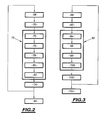
- la figure 2 est un organigramme d'un procédé de détection d'un interrupteur en court-circuit conforme à l'invention ;
- la figure 3 est un organigramme d'un procédé de détection d'un interrupteur bloqué dans un état ouvert conforme à l'invention ; et
- la figure 4 est un organigramme d'une variante d'un procédé de détection d'une défaillance d'un interrupteur conforme à l'invention.
Claims (10)
- Procédé de détection d'au moins une défaillance d'au moins un interrupteur à tester présent dans un convertisseur électronique (2) comportant des générateurs (Ti) raccordés entre eux par l'intermédiaire d'interrupteurs commandables (Pi, P'i, Si, S'i), de manière à relier les mêmes générateurs soit en parallèle, soit en série,
caractérisé en ce qu'il comprend les étapes de :commander (en 76 ; 94 ; 114) les interrupteurs du convertisseur (2) pour former un circuit électrique fermé reliant entre elles les bornes du ou de chaque interrupteur à tester,engendrer (en 78 ; 96 ; 110) un courant dans le circuit électrique fermé à l'aide d'une source d'alimentation raccordée entre des bornes d'entrée ou de sortie du convertisseur (2), etanalyser (en 80 ; 98 ; 118) aux bornes d'entrée ou de sortie du convertisseur les valeurs d'un paramètre représentatif de l'intensité du courant engendré dans le circuit électrique fermé pour en déduire une information de défaillance dudit au moins un interrupteur à tester. - Procédé selon la revendication 1, caractérisé en ce que, dans le cas où la défaillance à tester est un blocage dudit au moins un interrupteur de courant dans un état passant, le procédé comprend l'étape de commander (en 75 ; 116) ledit au moins un interrupteur à tester vers un état non-passant, et à déduire, lors de l'analyse (en 80 ; 118), que ledit au moins un interrupteur à tester est défaillant si ladite au moins une information représentative de l'intensité du courant correspond à un courant de court-circuit dans le circuit électrique fermé.
- Procédé selon l'une quelconque des revendications précédentes, caractérisé en ce que, dans le cas où la défaillance à tester est un blocage dudit au moins un interrupteur dans un état non-passant, le procédé comprend l'étape de commander (en 94 ; 116) ledit au moins un interrupteur vers un état passant, et à déduire, lors de l'analyse (en 98; 118), que ledit au moins un interrupteur à tester est défaillant si ladite au moins une information représentative de l'intensité du courant correspond à une absence de courant de court-circuit dans le circuit électrique fermé.
- Procédé selon l'une quelconque des revendications précédentes, caractérisé :en ce que les générateurs sont formés par des enroulements de transformateurs (Ti) indépendants magnétiquement les uns des autres,en ce que le convertisseur (2) comporte un circuit électrique primaire (10) raccordant entre eux les enroulements primaires des transformateurs (Ti), et un circuit électrique secondaire (12) raccordant entre eux les enroulements secondaires, les circuits primaire et secondaire étant électriquement isolés l'un de l'autre, eten ce que le procédé comporte l'étape de commander (en 75 ; 94) certains interrupteurs d'un seul de ces circuits électriques (10 ; 12) pour former ledit circuit électrique fermé et de commander (en 76 ; 96) certains interrupteurs de l'autre circuit électrique pour créer une différence de potentiel propre à engendrer un courant dans le circuit électrique fermé.
- Procédé selon la revendication 4, caractérisé en ce qu'il consiste à alimenter au moins deux enroulements de transformateur pour créer dans le circuit électrique fermé ladite différence de potentiel.
- Procédé selon la revendication 4 ou 5, caractérisé en ce que le ou chaque circuit électrique (10, 12) comporte plusieurs étages électriques formés chacun par deux enroulements consécutifs propres à être raccordés en parallèle, et par les interrupteurs raccordant entre eux ces deux enroulements, et en que le procédé comprend l'étape de commander (en 76 ; 94) uniquement le ou chaque interrupteur du même étage que celui contenant ledit au moins un interrupteur à tester pour former le circuit électrique fermé.
- Procédé selon la revendication 6, caractérisé en ce que le circuit électrique secondaire (12) comporte :N enroulements secondaires raccordés en série,un premier et un second jeu de N+1 interrupteurs (Si, S'i) commandables, les N+1 interrupteurs commandables d'un même jeu étant directement reliés entre eux par une extrémité commune et raccordés chacun par l'autre extrémité entre deux enroulements secondaires respectifs du circuit électronique secondaire (12), et en ce que le procédé comporte l'étape de commander (en 76 ; 96) uniquement un interrupteur du premier jeu et deux interrupteurs du second jeu pour créer ladite différence de potentiel dans le circuit électrique fermé.
- Procédé selon l'une quelconque des revendications 1 à 3, caractérisé en ce que le circuit électrique secondaire (12) comporte :caractérisé en ce qu'il comporte les étapes consistant à :N enroulements secondaires raccordés en série,un premier et un second jeu de N+1 interrupteurs (Si, S'i) commandables, les N+1 interrupteurs commandables d'un même jeu étant directement reliés entre eux par une extrémité commune et raccordés chacun par l'autre extrémité entre deux enroulements secondaires respectifs du circuit électronique secondaire (12),commander (en 114) uniquement au moins un interrupteur du circuit électrique secondaire (12) pour former ledit circuit électrique fermé,raccorder (en 110) une source d'alimentation (42) entre des bornes de sortie dudit circuit électrique secondaire (12), etanalyser (en 118) ledit paramètre représentatif de l'intensité du courant engendré au niveau des mêmes bornes que celles utilisées pour raccorder la source d'alimentation.
- Système de détection d'au moins une défaillance d'au moins un interrupteur (Pi, P'i, Si, S'i) dans un convertisseur (2) comportant des générateurs (Ti) raccordés entre eux par l'intermédiaire d'interrupteurs (Pi, P'i, Si, S'i) commandables de manière à raccorder les mêmes générateurs soit en parallèle, soit en série, caractérisé en ce qu'il comporte un calculateur électronique (50) apte à :commander les interrupteurs du convertisseur (2) pour former un circuit électrique fermé reliant entre elles les bornes du ou de chaque interrupteur à tester,créer une différence de potentiel propre à engendrer un courant dans le circuit électrique fermé à l'aide des générateurs (Ti) du convertisseur, etanalyser aux bornes d'entrée (16, 18) ou de sortie (26, 28) du convertisseur (2) les valeurs d'un paramètre représentatif de l'intensité du courant engendré par la différence de potentiel dans le circuit électrique fermé pour en déduire une information de défaillance dudit au moins un interrupteur à tester.
- Support (52) d'enregistrement d'informations comportant des instructions pour l'exécution d'un procédé de détection d'au moins une défaillance d'au moins un interrupteur (Pi, P'i, Si, S'i), conforme à l'une quelconque des revendications 1 à 8, lorsque lesdites instructions sont exécutées par un calculateur électronique (50).
Applications Claiming Priority (2)
| Application Number | Priority Date | Filing Date | Title |
|---|---|---|---|
| FR0214126 | 2002-11-12 | ||
| FR0214126A FR2847039B1 (fr) | 2002-11-12 | 2002-11-12 | Procede et systeme de detection d'au moins une defaillance d'au moins un interrupteur, et support d'enregistrement d'informations comportant des instructions pour l'execution du procede |
Publications (2)
| Publication Number | Publication Date |
|---|---|
| EP1420262A1 true EP1420262A1 (fr) | 2004-05-19 |
| EP1420262B1 EP1420262B1 (fr) | 2010-06-23 |
Family
ID=32116552
Family Applications (1)
| Application Number | Title | Priority Date | Filing Date |
|---|---|---|---|
| EP03356173A Expired - Lifetime EP1420262B1 (fr) | 2002-11-12 | 2003-11-10 | Procédé et système de détection d'au moins une défaillance d'au moins un interrupteur dans un convertisseur électronique |
Country Status (5)
| Country | Link |
|---|---|
| EP (1) | EP1420262B1 (fr) |
| AT (1) | ATE472109T1 (fr) |
| DE (1) | DE60333070D1 (fr) |
| ES (1) | ES2348454T3 (fr) |
| FR (1) | FR2847039B1 (fr) |
Cited By (2)
| Publication number | Priority date | Publication date | Assignee | Title |
|---|---|---|---|---|
| EP2416168A1 (fr) * | 2010-07-26 | 2012-02-08 | Semikron | Banc de test pour blocs de puissance électroniques. |
| CN114252752A (zh) * | 2021-12-22 | 2022-03-29 | 清华大学 | 全控桥式拓扑电路中功率管的故障诊断方法 |
Families Citing this family (1)
| Publication number | Priority date | Publication date | Assignee | Title |
|---|---|---|---|---|
| EP2080673B1 (fr) * | 2006-11-02 | 2014-03-12 | Panasonic Corporation | Dispositif d'alimentation électrique de véhicule |
Citations (2)
| Publication number | Priority date | Publication date | Assignee | Title |
|---|---|---|---|---|
| US5266891A (en) * | 1990-12-20 | 1993-11-30 | General Electric Company | Auto self test of AC motor system |
| FR2820561A1 (fr) * | 2001-02-05 | 2002-08-09 | Faiveley Transport | Circuit electronique de connexion en serie et/ou en parallele de generateurs |
Family Cites Families (3)
| Publication number | Priority date | Publication date | Assignee | Title |
|---|---|---|---|---|
| JPH06205599A (ja) * | 1992-12-28 | 1994-07-22 | Toshiba Corp | モータ駆動制御回路 |
| JPH0880056A (ja) * | 1994-09-02 | 1996-03-22 | Yaskawa Electric Corp | サーボ制御装置のパワートランジスタ故障検出方法 |
| JP3704400B2 (ja) * | 1996-07-03 | 2005-10-12 | ファナック株式会社 | モータのインバータ駆動制御装置における異常診断方法 |
-
2002
- 2002-11-12 FR FR0214126A patent/FR2847039B1/fr not_active Expired - Fee Related
-
2003
- 2003-11-10 DE DE60333070T patent/DE60333070D1/de not_active Expired - Lifetime
- 2003-11-10 AT AT03356173T patent/ATE472109T1/de active
- 2003-11-10 ES ES03356173T patent/ES2348454T3/es not_active Expired - Lifetime
- 2003-11-10 EP EP03356173A patent/EP1420262B1/fr not_active Expired - Lifetime
Patent Citations (2)
| Publication number | Priority date | Publication date | Assignee | Title |
|---|---|---|---|---|
| US5266891A (en) * | 1990-12-20 | 1993-11-30 | General Electric Company | Auto self test of AC motor system |
| FR2820561A1 (fr) * | 2001-02-05 | 2002-08-09 | Faiveley Transport | Circuit electronique de connexion en serie et/ou en parallele de generateurs |
Cited By (3)
| Publication number | Priority date | Publication date | Assignee | Title |
|---|---|---|---|---|
| EP2416168A1 (fr) * | 2010-07-26 | 2012-02-08 | Semikron | Banc de test pour blocs de puissance électroniques. |
| CN114252752A (zh) * | 2021-12-22 | 2022-03-29 | 清华大学 | 全控桥式拓扑电路中功率管的故障诊断方法 |
| CN114252752B (zh) * | 2021-12-22 | 2022-12-16 | 清华大学 | 全控桥式拓扑电路中功率管的故障诊断方法 |
Also Published As
| Publication number | Publication date |
|---|---|
| ATE472109T1 (de) | 2010-07-15 |
| ES2348454T3 (es) | 2010-12-07 |
| FR2847039B1 (fr) | 2005-01-21 |
| FR2847039A1 (fr) | 2004-05-14 |
| DE60333070D1 (de) | 2010-08-05 |
| EP1420262B1 (fr) | 2010-06-23 |
Similar Documents
| Publication | Publication Date | Title |
|---|---|---|
| EP0843400B1 (fr) | Dispositif de détection préventive de défauts avec identification du type de charge | |
| FR2922374A1 (fr) | Dispositif de suppression de courant entrant | |
| EP2634884A1 (fr) | Chaîne d'alimentation d'une machine électrique synchrone, système de traction électrique comprenant une telle chaîne, et procédé de commande d'une telle chaîne | |
| EP0038259A1 (fr) | Procédé d'identification de phases en défaut dans un réseau de distribution électrique | |
| EP3300249B1 (fr) | Procédé et système de surveillance et de diagnostic d'une architecture photovoltaïque | |
| EP1420262B1 (fr) | Procédé et système de détection d'au moins une défaillance d'au moins un interrupteur dans un convertisseur électronique | |
| EP3384592A1 (fr) | Procede et dispositif de detection d'un arc electrique dans une installation photovoltaïque | |
| FR2853466A1 (fr) | Procede de determination de l'instant de fermeture d'un disjoncteur sur une ligne haute tension | |
| EP2346154A1 (fr) | Système d'alimentation d'un élément, parmi un rotor et un stator d'une machine électrique, et procédé de commande d'un tel système | |
| EP3559965B1 (fr) | Installation électrique haute tension continue et procédé de contrôle d'un appareil de coupure dans une telle installation | |
| FR2582169A1 (fr) | Appareil amplificateur | |
| CA2396190C (fr) | Procede et dispositif de test d'un module de puissance | |
| FR2980058A1 (fr) | Procede de commande d'un interrupteur commande pilotant l'alimentation d'un moteur electrique | |
| FR2563956A1 (fr) | Circuit integrable pour l'echantillonnage de la tension d'une charge | |
| EP2107382B1 (fr) | Détection de l'état des éléments d'une branche électrique comprenant une charge et un interrupteur | |
| EP0304363A1 (fr) | Régulateur de puissance, notamment pour le balisage d'aéroports | |
| FR3079305A1 (fr) | Procede de determination d'au moins deux resistances equivalentes d'isolement d'un systeme electrique | |
| FR2819063A1 (fr) | Procede et circuit pour reduire la dissipation thermique dans un boitier d'automate programmable industriel, et automate programmable industriel integrant un tel circuit | |
| FR2881233A1 (fr) | Outil de programmation destine a la configuration d'une installation domotique | |
| WO2022096836A1 (fr) | Dispositifs de surveillance et de protection de circuits de puissance | |
| CA2833134A1 (fr) | Procede de commande d'un appareil d'interruption de courant dans un reseau electrique haute tension | |
| CA2967155A1 (fr) | Procede de manoeuvre de charges capacitives et dispositif pour la mise en oeuvre du procede | |
| EP2980941A1 (fr) | Dispositif d'adaptation d'un signal d'alimentation électrique, système d'alimentation électrique et procédé d'adaptation d'un signal d'alimentation électrique associés | |
| FR2754065A1 (fr) | Circuit de simulation d'un composant a retournement | |
| EP0285532A1 (fr) | Dispositif de détection de défaut dans un réseau triphasé alimentant des charges par des trains d'ondes entières |
Legal Events
| Date | Code | Title | Description |
|---|---|---|---|
| PUAI | Public reference made under article 153(3) epc to a published international application that has entered the european phase |
Free format text: ORIGINAL CODE: 0009012 |
|
| AK | Designated contracting states |
Kind code of ref document: A1 Designated state(s): AT BE BG CH CY CZ DE DK EE ES FI FR GB GR HU IE IT LI LU MC NL PT RO SE SI SK TR |
|
| AX | Request for extension of the european patent |
Extension state: AL LT LV MK |
|
| 17P | Request for examination filed |
Effective date: 20040714 |
|
| RAP1 | Party data changed (applicant data changed or rights of an application transferred) |
Owner name: ALSTOM |
|
| AKX | Designation fees paid |
Designated state(s): AT BE BG CH CY CZ DE DK EE ES FI FR GB GR HU IE IT LI LU MC NL PT RO SE SI SK TR |
|
| 17Q | First examination report despatched |
Effective date: 20060925 |
|
| GRAP | Despatch of communication of intention to grant a patent |
Free format text: ORIGINAL CODE: EPIDOSNIGR1 |
|
| RTI1 | Title (correction) |
Free format text: METHOD AND SYSTEM FOR DETECTING AT LEAST ONE FAILURE OF AT LEAST ONE SWITCH IN AN ELECTRONIC CONVERTER |
|
| GRAS | Grant fee paid |
Free format text: ORIGINAL CODE: EPIDOSNIGR3 |
|
| RAP1 | Party data changed (applicant data changed or rights of an application transferred) |
Owner name: ALSTOM TRANSPORT SA |
|
| GRAA | (expected) grant |
Free format text: ORIGINAL CODE: 0009210 |
|
| AK | Designated contracting states |
Kind code of ref document: B1 Designated state(s): AT BE BG CH CY CZ DE DK EE ES FI FR GB GR HU IE IT LI LU MC NL PT RO SE SI SK TR |
|
| REG | Reference to a national code |
Ref country code: CH Ref legal event code: EP |
|
| REG | Reference to a national code |
Ref country code: IE Ref legal event code: FG4D Free format text: LANGUAGE OF EP DOCUMENT: FRENCH |
|
| REF | Corresponds to: |
Ref document number: 60333070 Country of ref document: DE Date of ref document: 20100805 Kind code of ref document: P |
|
| REG | Reference to a national code |
Ref country code: NL Ref legal event code: VDEP Effective date: 20100623 |
|
| PG25 | Lapsed in a contracting state [announced via postgrant information from national office to epo] |
Ref country code: SE Free format text: LAPSE BECAUSE OF FAILURE TO SUBMIT A TRANSLATION OF THE DESCRIPTION OR TO PAY THE FEE WITHIN THE PRESCRIBED TIME-LIMIT Effective date: 20100623 |
|
| REG | Reference to a national code |
Ref country code: ES Ref legal event code: FG2A Effective date: 20101124 |
|
| PG25 | Lapsed in a contracting state [announced via postgrant information from national office to epo] |
Ref country code: FI Free format text: LAPSE BECAUSE OF FAILURE TO SUBMIT A TRANSLATION OF THE DESCRIPTION OR TO PAY THE FEE WITHIN THE PRESCRIBED TIME-LIMIT Effective date: 20100623 Ref country code: SI Free format text: LAPSE BECAUSE OF FAILURE TO SUBMIT A TRANSLATION OF THE DESCRIPTION OR TO PAY THE FEE WITHIN THE PRESCRIBED TIME-LIMIT Effective date: 20100623 |
|
| PG25 | Lapsed in a contracting state [announced via postgrant information from national office to epo] |
Ref country code: GR Free format text: LAPSE BECAUSE OF FAILURE TO SUBMIT A TRANSLATION OF THE DESCRIPTION OR TO PAY THE FEE WITHIN THE PRESCRIBED TIME-LIMIT Effective date: 20100924 |
|
| PG25 | Lapsed in a contracting state [announced via postgrant information from national office to epo] |
Ref country code: EE Free format text: LAPSE BECAUSE OF FAILURE TO SUBMIT A TRANSLATION OF THE DESCRIPTION OR TO PAY THE FEE WITHIN THE PRESCRIBED TIME-LIMIT Effective date: 20100623 Ref country code: NL Free format text: LAPSE BECAUSE OF FAILURE TO SUBMIT A TRANSLATION OF THE DESCRIPTION OR TO PAY THE FEE WITHIN THE PRESCRIBED TIME-LIMIT Effective date: 20100623 |
|
| REG | Reference to a national code |
Ref country code: IE Ref legal event code: FD4D |
|
| PG25 | Lapsed in a contracting state [announced via postgrant information from national office to epo] |
Ref country code: CZ Free format text: LAPSE BECAUSE OF FAILURE TO SUBMIT A TRANSLATION OF THE DESCRIPTION OR TO PAY THE FEE WITHIN THE PRESCRIBED TIME-LIMIT Effective date: 20100623 Ref country code: CY Free format text: LAPSE BECAUSE OF FAILURE TO SUBMIT A TRANSLATION OF THE DESCRIPTION OR TO PAY THE FEE WITHIN THE PRESCRIBED TIME-LIMIT Effective date: 20100623 Ref country code: PT Free format text: LAPSE BECAUSE OF FAILURE TO SUBMIT A TRANSLATION OF THE DESCRIPTION OR TO PAY THE FEE WITHIN THE PRESCRIBED TIME-LIMIT Effective date: 20101025 Ref country code: RO Free format text: LAPSE BECAUSE OF FAILURE TO SUBMIT A TRANSLATION OF THE DESCRIPTION OR TO PAY THE FEE WITHIN THE PRESCRIBED TIME-LIMIT Effective date: 20100623 Ref country code: SK Free format text: LAPSE BECAUSE OF FAILURE TO SUBMIT A TRANSLATION OF THE DESCRIPTION OR TO PAY THE FEE WITHIN THE PRESCRIBED TIME-LIMIT Effective date: 20100623 |
|
| PG25 | Lapsed in a contracting state [announced via postgrant information from national office to epo] |
Ref country code: IE Free format text: LAPSE BECAUSE OF FAILURE TO SUBMIT A TRANSLATION OF THE DESCRIPTION OR TO PAY THE FEE WITHIN THE PRESCRIBED TIME-LIMIT Effective date: 20100623 Ref country code: DK Free format text: LAPSE BECAUSE OF FAILURE TO SUBMIT A TRANSLATION OF THE DESCRIPTION OR TO PAY THE FEE WITHIN THE PRESCRIBED TIME-LIMIT Effective date: 20100623 |
|
| PLBE | No opposition filed within time limit |
Free format text: ORIGINAL CODE: 0009261 |
|
| STAA | Information on the status of an ep patent application or granted ep patent |
Free format text: STATUS: NO OPPOSITION FILED WITHIN TIME LIMIT |
|
| 26N | No opposition filed |
Effective date: 20110324 |
|
| PG25 | Lapsed in a contracting state [announced via postgrant information from national office to epo] |
Ref country code: MC Free format text: LAPSE BECAUSE OF NON-PAYMENT OF DUE FEES Effective date: 20101130 |
|
| REG | Reference to a national code |
Ref country code: DE Ref legal event code: R097 Ref document number: 60333070 Country of ref document: DE Effective date: 20110323 |
|
| GBPC | Gb: european patent ceased through non-payment of renewal fee |
Effective date: 20101110 |
|
| PG25 | Lapsed in a contracting state [announced via postgrant information from national office to epo] |
Ref country code: GB Free format text: LAPSE BECAUSE OF NON-PAYMENT OF DUE FEES Effective date: 20101110 |
|
| PG25 | Lapsed in a contracting state [announced via postgrant information from national office to epo] |
Ref country code: BG Free format text: LAPSE BECAUSE OF FAILURE TO SUBMIT A TRANSLATION OF THE DESCRIPTION OR TO PAY THE FEE WITHIN THE PRESCRIBED TIME-LIMIT Effective date: 20100623 Ref country code: HU Free format text: LAPSE BECAUSE OF FAILURE TO SUBMIT A TRANSLATION OF THE DESCRIPTION OR TO PAY THE FEE WITHIN THE PRESCRIBED TIME-LIMIT Effective date: 20101224 Ref country code: LU Free format text: LAPSE BECAUSE OF NON-PAYMENT OF DUE FEES Effective date: 20101110 |
|
| PG25 | Lapsed in a contracting state [announced via postgrant information from national office to epo] |
Ref country code: TR Free format text: LAPSE BECAUSE OF FAILURE TO SUBMIT A TRANSLATION OF THE DESCRIPTION OR TO PAY THE FEE WITHIN THE PRESCRIBED TIME-LIMIT Effective date: 20100623 |
|
| PG25 | Lapsed in a contracting state [announced via postgrant information from national office to epo] |
Ref country code: BG Free format text: LAPSE BECAUSE OF FAILURE TO SUBMIT A TRANSLATION OF THE DESCRIPTION OR TO PAY THE FEE WITHIN THE PRESCRIBED TIME-LIMIT Effective date: 20100923 |
|
| REG | Reference to a national code |
Ref country code: FR Ref legal event code: TP Owner name: ALSTOM TRANSPORT TECHNOLOGIES, FR Effective date: 20141209 |
|
| REG | Reference to a national code |
Ref country code: CH Ref legal event code: PUE Owner name: ALSTOM TRANSPORT TECHNOLOGIES, FR Free format text: FORMER OWNER: ALSTOM TRANSPORT SA, FR |
|
| REG | Reference to a national code |
Ref country code: DE Ref legal event code: R081 Ref document number: 60333070 Country of ref document: DE Owner name: SPEEDINNOV, FR Free format text: FORMER OWNER: ALSTOM TRANSPORT S.A., LEVALLOIS-PERRET, FR Ref country code: DE Ref legal event code: R081 Ref document number: 60333070 Country of ref document: DE Owner name: ALSTOM TRANSPORT TECHNOLOGIES, FR Free format text: FORMER OWNER: ALSTOM TRANSPORT S.A., LEVALLOIS-PERRET, FR |
|
| REG | Reference to a national code |
Ref country code: FR Ref legal event code: PLFP Year of fee payment: 13 |
|
| REG | Reference to a national code |
Ref country code: FR Ref legal event code: PLFP Year of fee payment: 14 |
|
| REG | Reference to a national code |
Ref country code: DE Ref legal event code: R081 Ref document number: 60333070 Country of ref document: DE Owner name: SPEEDINNOV, FR Free format text: FORMER OWNER: ALSTOM TRANSPORT TECHNOLOGIES, LEVALLOIS-PERRET, FR |
|
| REG | Reference to a national code |
Ref country code: CH Ref legal event code: PUE Owner name: SPEEDINNOV SOCIETE PAR ACTIONS SIMPLIFIEE, FR Free format text: FORMER OWNER: ALSTOM TRANSPORT TECHNOLOGIES, FR |
|
| REG | Reference to a national code |
Ref country code: ES Ref legal event code: PC2A Owner name: SPEEDINNOV Effective date: 20171027 Ref country code: FR Ref legal event code: TP Owner name: SPEEDINNOV, FR Effective date: 20171003 |
|
| REG | Reference to a national code |
Ref country code: FR Ref legal event code: PLFP Year of fee payment: 15 |
|
| REG | Reference to a national code |
Ref country code: AT Ref legal event code: PC Ref document number: 472109 Country of ref document: AT Kind code of ref document: T Owner name: SPEEDINNOV, FR Effective date: 20180221 |
|
| PGFP | Annual fee paid to national office [announced via postgrant information from national office to epo] |
Ref country code: IT Payment date: 20221124 Year of fee payment: 20 Ref country code: FR Payment date: 20221128 Year of fee payment: 20 Ref country code: DE Payment date: 20221123 Year of fee payment: 20 Ref country code: AT Payment date: 20221121 Year of fee payment: 20 |
|
| PGFP | Annual fee paid to national office [announced via postgrant information from national office to epo] |
Ref country code: CH Payment date: 20221121 Year of fee payment: 20 Ref country code: BE Payment date: 20221118 Year of fee payment: 20 |
|
| PGFP | Annual fee paid to national office [announced via postgrant information from national office to epo] |
Ref country code: ES Payment date: 20230125 Year of fee payment: 20 |
|
| REG | Reference to a national code |
Ref country code: DE Ref legal event code: R071 Ref document number: 60333070 Country of ref document: DE |
|
| REG | Reference to a national code |
Ref country code: CH Ref legal event code: PL |
|
| REG | Reference to a national code |
Ref country code: ES Ref legal event code: FD2A Effective date: 20231124 |
|
| P01 | Opt-out of the competence of the unified patent court (upc) registered |
Effective date: 20231025 |
|
| REG | Reference to a national code |
Ref country code: BE Ref legal event code: MK Effective date: 20231110 |
|
| REG | Reference to a national code |
Ref country code: AT Ref legal event code: MK07 Ref document number: 472109 Country of ref document: AT Kind code of ref document: T Effective date: 20231110 |
|
| PG25 | Lapsed in a contracting state [announced via postgrant information from national office to epo] |
Ref country code: ES Free format text: LAPSE BECAUSE OF EXPIRATION OF PROTECTION Effective date: 20231111 |
|
| PG25 | Lapsed in a contracting state [announced via postgrant information from national office to epo] |
Ref country code: ES Free format text: LAPSE BECAUSE OF EXPIRATION OF PROTECTION Effective date: 20231111 |