EP1420250A1 - Gene inspection apparatus and target nucleic acid extraction method using the same - Google Patents
Gene inspection apparatus and target nucleic acid extraction method using the same Download PDFInfo
- Publication number
- EP1420250A1 EP1420250A1 EP02755725A EP02755725A EP1420250A1 EP 1420250 A1 EP1420250 A1 EP 1420250A1 EP 02755725 A EP02755725 A EP 02755725A EP 02755725 A EP02755725 A EP 02755725A EP 1420250 A1 EP1420250 A1 EP 1420250A1
- Authority
- EP
- European Patent Office
- Prior art keywords
- gene
- nucleic acid
- dna microarray
- optical signal
- dna
- Prior art date
- Legal status (The legal status is an assumption and is not a legal conclusion. Google has not performed a legal analysis and makes no representation as to the accuracy of the status listed.)
- Withdrawn
Links
Images





Classifications
-
- B—PERFORMING OPERATIONS; TRANSPORTING
- B01—PHYSICAL OR CHEMICAL PROCESSES OR APPARATUS IN GENERAL
- B01L—CHEMICAL OR PHYSICAL LABORATORY APPARATUS FOR GENERAL USE
- B01L3/00—Containers or dishes for laboratory use, e.g. laboratory glassware; Droppers
- B01L3/50—Containers for the purpose of retaining a material to be analysed, e.g. test tubes
- B01L3/502—Containers for the purpose of retaining a material to be analysed, e.g. test tubes with fluid transport, e.g. in multi-compartment structures
- B01L3/5025—Containers for the purpose of retaining a material to be analysed, e.g. test tubes with fluid transport, e.g. in multi-compartment structures for parallel transport of multiple samples
- B01L3/50255—Multi-well filtration
-
- B—PERFORMING OPERATIONS; TRANSPORTING
- B01—PHYSICAL OR CHEMICAL PROCESSES OR APPARATUS IN GENERAL
- B01J—CHEMICAL OR PHYSICAL PROCESSES, e.g. CATALYSIS OR COLLOID CHEMISTRY; THEIR RELEVANT APPARATUS
- B01J2219/00—Chemical, physical or physico-chemical processes in general; Their relevant apparatus
- B01J2219/00274—Sequential or parallel reactions; Apparatus and devices for combinatorial chemistry or for making arrays; Chemical library technology
- B01J2219/00583—Features relative to the processes being carried out
- B01J2219/00603—Making arrays on substantially continuous surfaces
- B01J2219/00605—Making arrays on substantially continuous surfaces the compounds being directly bound or immobilised to solid supports
- B01J2219/00608—DNA chips
-
- B—PERFORMING OPERATIONS; TRANSPORTING
- B01—PHYSICAL OR CHEMICAL PROCESSES OR APPARATUS IN GENERAL
- B01J—CHEMICAL OR PHYSICAL PROCESSES, e.g. CATALYSIS OR COLLOID CHEMISTRY; THEIR RELEVANT APPARATUS
- B01J2219/00—Chemical, physical or physico-chemical processes in general; Their relevant apparatus
- B01J2219/00274—Sequential or parallel reactions; Apparatus and devices for combinatorial chemistry or for making arrays; Chemical library technology
- B01J2219/00583—Features relative to the processes being carried out
- B01J2219/00603—Making arrays on substantially continuous surfaces
- B01J2219/00605—Making arrays on substantially continuous surfaces the compounds being directly bound or immobilised to solid supports
- B01J2219/00612—Making arrays on substantially continuous surfaces the compounds being directly bound or immobilised to solid supports the surface being inorganic
-
- B—PERFORMING OPERATIONS; TRANSPORTING
- B01—PHYSICAL OR CHEMICAL PROCESSES OR APPARATUS IN GENERAL
- B01J—CHEMICAL OR PHYSICAL PROCESSES, e.g. CATALYSIS OR COLLOID CHEMISTRY; THEIR RELEVANT APPARATUS
- B01J2219/00—Chemical, physical or physico-chemical processes in general; Their relevant apparatus
- B01J2219/00274—Sequential or parallel reactions; Apparatus and devices for combinatorial chemistry or for making arrays; Chemical library technology
- B01J2219/00583—Features relative to the processes being carried out
- B01J2219/00603—Making arrays on substantially continuous surfaces
- B01J2219/00639—Making arrays on substantially continuous surfaces the compounds being trapped in or bound to a porous medium
- B01J2219/00641—Making arrays on substantially continuous surfaces the compounds being trapped in or bound to a porous medium the porous medium being continuous, e.g. porous oxide substrates
-
- B—PERFORMING OPERATIONS; TRANSPORTING
- B01—PHYSICAL OR CHEMICAL PROCESSES OR APPARATUS IN GENERAL
- B01J—CHEMICAL OR PHYSICAL PROCESSES, e.g. CATALYSIS OR COLLOID CHEMISTRY; THEIR RELEVANT APPARATUS
- B01J2219/00—Chemical, physical or physico-chemical processes in general; Their relevant apparatus
- B01J2219/00274—Sequential or parallel reactions; Apparatus and devices for combinatorial chemistry or for making arrays; Chemical library technology
- B01J2219/00718—Type of compounds synthesised
- B01J2219/0072—Organic compounds
- B01J2219/00722—Nucleotides
-
- B—PERFORMING OPERATIONS; TRANSPORTING
- B01—PHYSICAL OR CHEMICAL PROCESSES OR APPARATUS IN GENERAL
- B01L—CHEMICAL OR PHYSICAL LABORATORY APPARATUS FOR GENERAL USE
- B01L2300/00—Additional constructional details
- B01L2300/08—Geometry, shape and general structure
- B01L2300/0809—Geometry, shape and general structure rectangular shaped
- B01L2300/0819—Microarrays; Biochips
-
- B—PERFORMING OPERATIONS; TRANSPORTING
- B01—PHYSICAL OR CHEMICAL PROCESSES OR APPARATUS IN GENERAL
- B01L—CHEMICAL OR PHYSICAL LABORATORY APPARATUS FOR GENERAL USE
- B01L2400/00—Moving or stopping fluids
- B01L2400/04—Moving fluids with specific forces or mechanical means
- B01L2400/0475—Moving fluids with specific forces or mechanical means specific mechanical means and fluid pressure
- B01L2400/0487—Moving fluids with specific forces or mechanical means specific mechanical means and fluid pressure fluid pressure, pneumatics
-
- C—CHEMISTRY; METALLURGY
- C40—COMBINATORIAL TECHNOLOGY
- C40B—COMBINATORIAL CHEMISTRY; LIBRARIES, e.g. CHEMICAL LIBRARIES
- C40B40/00—Libraries per se, e.g. arrays, mixtures
- C40B40/04—Libraries containing only organic compounds
- C40B40/06—Libraries containing nucleotides or polynucleotides, or derivatives thereof
Definitions
- the present invention relates to an apparatus that detects the gene expression level and the presence or absence of mutation, and a method of detecting a target nucleic acid using this apparatus.
- the current method of examining genes comprises: a step of extracting nucleic acids from a living sample; a step of amplifying a target gene to be examined using a nucleic acid amplifying method such as a PCR method or a NASBA method; a step of labeling the nucleic acid using a marker substance such as a radioisotope (hereinafter referred to as an "RI") or a fluorescent molecule; and a step of measuring the nucleotide sequence of the labeled target gene or its concentration.
- a nucleic acid amplifying method such as a PCR method or a NASBA method
- RI radioisotope
- fluorescent molecule a fluorescent molecule
- capillary electrophoresis apparatuses which can quickly treat a large number of samples using a nucleic acid labeled with fluorescence and a plurality of capillaries. These apparatuses can analyze a large number of samples in a time about one-third or a quarter of the time required by methods using conventional electrophoresis apparatuses.
- an examining method which simultaneously examines a plurality of genes using a DNA chip.
- the DNA chip is manufactured by immobilizing a large number of cDNA probes on the surface of a glass substrate, or by utilizing a semiconductor manufacturing process to synthesize a large number of oligo probes in a fine area on a silicon. With either of these methods, the DNA chip can simultaneously determine the presence of plural types of target sequences contained in a sample.
- the use of the DNA chip has made it possible to quickly analyze the amount of expression of a large number of genes as well as a plurality of mutations.
- many genes have been classified into a plurality of groups (that is, clustering) or information on changes in genes associated with development or differentiation has been obtained. Gene information thus obtained is utilized as an easily accessible database via the Internet.
- an electrophoresis method or a microarray method is used to examine the amount of expression of genes and to analyze mutation.
- the electrophoresis method requires a long time for examinations and limits the types of examinations that can be made at one time.
- a method of analyzing a gene using a DNA chip allows a large number of examinations to be made at one time but requires a long time for examinations.
- this method as a whole requires many examining steps and complicated procedures.
- the results of analysis based on this method are not reproducible.
- methods have been developed which allow results obtained to be appropriately reproduced and which are intended to quickly finish examinations that are similar to those of the method using a DNA chip.
- a gene examining system is desired to be developed which can easily and quickly examine a plurality of genes.
- a gene examining apparatus utilizing a computer, the apparatus comprising:
- a method of examining a gene using the apparatus set forth in the first embodiment comprising;
- an apparatus which can easily detect the expression level of a gene from one subject and the presence of mutation in the gene in a short time.
- the apparatus uses a nucleic acid immobilized on a substrate and having a known sequence, to detect a nucleic acid strand contained in a subject and having a particular sequence.
- the apparatus according to the embodiment of the present invention conceptually comprises a single strand nucleic acid (that is, a nucleic acid probe) as a reagent immobilized on a substrate.
- the immobilized nucleic acid probe is contacted with a nucleic acid contained in a sample and labeled with an optical marker substance. If the nucleic acid contained in the sample has a sequence complementary to the nucleic acid probe, it is hybridized with the nucleic acid.
- the "optical marker substance” means a fluorescent substance, a chemical light-emitting substance, a biological light-emitting substance, and any other substances that can emit light as an observable signal.
- the apparatus according to the embodiment of the present invention is a gene examining apparatus utilizing a computer.
- a gene examining apparatus 1 comprises a microscope 3 used to microscopically observe an event in DMA microarrays 22 in which a sample is caused to react, a stage 4 provided in the microscope 3 in order to support a reaction block 100 that accommodates a slide chip 2 comprising the DNA microarrays 22, imaging means 5 for picking up an image of a signal from an optical marker substance in each DNA microarray 22, the substance being observed using the microscope 3, an XY stage controller 7 that controls a motor driver 6 connected to the stage 4 in order to change the position of a visual field observed using the microscope 3, a zoom means driving device 18 that drivingly controls zoom means 17 for enlarging and/or reducing the visual field observed using the microscope 3, a pump driver 8 that transports a fluid via a joint section connected to the DNA microarrays 22, a temperature controller 9 that regulates the temperature of each DNA microarray via a heater section 101 arranged in contact with the DNA microarray 22, and a computer 10 connected directly or indirectly to all the devices included in the gene examining apparatus 1 to integral
- the joint section 120 is connected to the DNA microarrays 22 in the reaction block 100 so as not to leak the fluid contained in the DNA microarrays 22 to the exterior.
- a terminal of the joint section 120 is connected to the pump driver via a tube.
- the pump driver 8 is in turn connected to a reagent holding section containing a desired reagent and the like. The pump driver 8 moves a fluid into and out of the DNA microarrays in response to instructions from the computer 10 in accordance with an analysis program.
- the heater section 101 is arranged between the slide chip and the stage 4.
- the heater section is connected to the temperature controller 9 and has its temperature regulated by the temperature controller in accordance with instructions from the computer 10.
- the heater section 101 comprises a number of heaters the number of which corresponds to the number of DNA microarrays 22 of the reaction block 100 and which can be individually controlled by the controller 9.
- the computer 10 includes components provided in common computers.
- the components provided in the computer 10 may include, for example, at least a CPU 11 (Central Processing Unit) that is a main control section integrally controlling each section of the computer 10, a memory 12 that stores various programs on which control by the CPU 11 is based and files for image data or the like which is to be displayed, a RAM (Random Access Memory) 13 that temporarily stores, for example, the results of execution by the CPU 11, an image processing section 14 that generates image data in accordance with instructions from the CPU 11 based on a program or the like, an input section 15 such as a keyboard and a mouse which is used by an operator, for example, a user to input information into the computer 10, and a display section 16 such as a display or a printer which displays information in accordance with instructions from the computer 10.
- a CPU 11 Central Processing Unit
- memory 12 that stores various programs on which control by the CPU 11 is based and files for image data or the like which is to be displayed
- a RAM (Random Access Memory) 13 that temporarily
- Information obtained by the imaging means is transmitted to the image processing section 14.
- the image processing section 14 processes the information in response to instructions from the CPU 11 in accordance with the analysis program stored in the memory 12.
- the information is thus digitized as the intensity of an optical signal emitted by an optical marker substance, for example, a fluorescence intensity.
- the computer that can be used in the present invention may be any electronic computer that can be commonly used.
- the microscope that can be used in the present invention may be any fluorescent microscope that is commonly used.
- the microscope may be, for example, the fluorescent microscope AX-70 or BX-42TFR manufactured by Olympus.
- the present invention is not limited to these microscopes.
- the imaging means that can be used in the present invention has only to be well-known means that can be used to pick up an image of a common optical signal corresponding to the type of the optical marker substance.
- the imaging means is means for picking up a fluorescent image.
- imaging means includes, for example, a CCD (Charge Coupled Device) and a scanning confocal camera.
- CCD Charge Coupled Device
- scanning confocal camera a scanning confocal camera.
- the present invention is not limited these imaging means.
- the CCD camera has only to be one commonly used.
- it may be a common digital camera such as a MegaPlus CCD camera manufactured by Kodac or a Cool Pix camera manufactured by Photometric.
- the scanning confocal camera also has only to be one commonly used.
- the temperature regulating section regulating the temperature of each DNA microarray 22 may include a heating element (for example, an electric heater, an electromagnetic heater, a water bath, an air bath, and Peltier element) that contacts directly or indirectly with the slide chip 2, comprising the DNA microarrays 22, to transmit heat to the slide chip 2, a sensor that sense the temperature of the slide chip 2, and a temperature controller that controls the heating of the heating element in accordance with control provided by the computer and information transmitted by the sensor.
- a heating element for example, an electric heater, an electromagnetic heater, a water bath, an air bath, and Peltier element
- the computer may be connected to the Integrated Services Digital Network (hereinafter referred to as the "ISDN") or to a telephone line via a modem.
- ISDN Integrated Services Digital Network
- the stage 4 provided in the above embodiment can be moved in an X and Y directions by the XY stage controller 7 as described above.
- changes in visual field are not limited to such movement of the stage.
- the visual field may be changed, for example, by the imaging means itself or using various scanning mechanisms such as means for changing an optical path joining the imaging means 5 and the microarrays 22 together.
- FIGS. 2(A) and 2(B) show an embodiment of the DNA microarrays 22 used in the present invention.
- FIG. 2(A) is a plan view of the slide chip 2.
- the slide chip 2 comprises four DNA microarrays 22 in which reaction occurs.
- FIG. 2(B) is a sectional view of the slide chip 2.
- the slide chip 2 comprises a filter 19 composed of a porous material and a support plate 20 that supports the filter 19.
- Channels contained in the filter 19 preferably have branches. However, the channels need not necessarily have branches.
- the support plate 20 is composed of two members, support plates 20a and 20b. These two members are joined together while sandwiching the filter 19 between them, to constitute the slide chip 2.
- the support plates 20a and 20b, located over and under the filter 19 have openings 21 that define the DNA microarrays 22.
- the filter 19, located between the two support plates 20a and 20b, is composed of one piece containing all the four DNA microarrays.
- the filter 19 is flat and extends two-dimensionally over an area including all the four DNA microarrays.
- the support plate 20 is preferably composed of a shielding member and more preferably of a dark black member.
- the supports 20a and 20b are joined together while sandwiching the filter 19 between them.
- the filter 19 may be composed of any material provided that it is not damaged within the range of temperature control carried out in the filter.
- the DNA microarrays 22 refer to parts of the filter 19 that are exposed from the openings 21 formed in the support plate 20.
- the channels contained in the filter 19 may or may not have branches, but preferably have branches. All the channels 24 provided in the filter 19 are preferably arranged at almost equal intervals. However, all the channels 24 may be arranged at almost equal intervals at least in the microarrays 22, exposed from the support plate 20.
- a filter 19 which has a constant thickness and which comprises channels 24 the shapes of which are made as equal to one another as possible, the channels have an almost uniform volume.
- the filter 19 may be sufficiently thin and each channel 24 may have a sufficiently small diameter. Then, a required amount of sample and/or reagent can be distributed to a large number of channels.
- channels the number of which is required to accommodate a desired amount of liquid, per particular area of one surface of the filter, and supplying a sample and/or a reagent to this predetermined area stable analysis can be executed within the porous film of the filter 19. For example, the temperature of the liquid in the chambers can be increased or reduced by contacting one or both surfaces of the filter 19 with a gas having a controlled desired temperature.
- the capillary must be shaped to have a flat surface.
- FIG. 2(C) shown immediately above the slide chip 2 in FIG. 2(A) is an enlarged view of the microarray 22 (also referred to as the "DNA microarray”).
- the plurality of channels 24 are present in the microarray 22.
- a nucleic acid probe is immobilized on the inner wall of some of the channels in the microarray 22.
- An area to which the nucleic acid probes are fixed is a probe spot 23 (also simply referred to as a "spot").
- each DNA microarray 22 comprises a plurality of probe spots 23.
- FIG. 2(D) is an enlarged view of the probe spots and their periphery.
- the channels 24 included in each probe spot 23 are shown by black circles.
- the channels 24 to which no probes are fixed are shown by white circles.
- the probe spot 23 is an area composed of the channels 24 comprising a plurality of probes. Normally, one probe spot 23 may be considered to be a minimum unit to which one type of probe is fixed, for the channels 24 present in parts of the filter 19 that are exposed from the support plate 20. That is, the probe has only to be immobilized on the inner wall surface of each of the channels included in the probe spot 23.
- FIGS. 2(C) and 2(D) show generally circular areas
- the contour of the probe spot 23 may be a general circle, a general rectangle, or a polygon.
- the same probe may be immobilized on a plurality of probe spots 23 as desired.
- the inner wall of each channel may be subjected to surface treatment to adjust frictional resistance to a fluid or the ability of the probes to adsorb a reagent.
- the size of the present slide chip is 0.5 to 20.0 cm ⁇ 0.5 to 20 cm ⁇ 0.01 to 1.0 cm, preferably 1.0 to 10.0 cm ⁇ 1.0 to 10.0 cm ⁇ 0.05 to 0.5 cm. Particularly preferably, it may be 3.0 to 8.0 cm ⁇ 3.0 to 8.0 cm ⁇ 0.05 to 0.2 cm.
- An example of an actually produced slide chip has a size of about 7.5 cm ⁇ about 2.5 cm ⁇ about 0.1 cm.
- the present microarray is 3.0 mm 2 to 16 mm 2 , preferably 12.0 to 400 mm 2 , particularly preferably 20.0 to 100.0 mm 2 .
- Circular microarrays on the actually produced slide chip have a diameter of about 6 mm (about 28.3 mm 2 ).
- the probe spot included in the present DNA microarray has a diameter of 100 to 300 ⁇ m, preferably 120 ⁇ m. Ten to thousand probe spots, preferably 400 probe spots may be provided per DNA microarray.
- the porous filter has only to have an openness of 0.05 to 0.5 ⁇ m, preferably 0.2 ⁇ m. Different types of nucleic acid probes may be immobilized on the respective probe spots.
- the term "DNA microarray” as used herein refers to one reaction unit in which one type of reaction occurs.
- the DNA microarray comprises a plurality of probe spots 23 each composed of a plurality of channels 24 to which the respective nucleic probes are fixed.
- probes are immobilized on a surface of a slide glass to form a two-dimensionally extending reaction area.
- the DNA microarray of the present invention has not only a two-dimensional extension over the surface of the substrate but also an extension perpendicular to the surface (that is, extending in the direction of the thickness of the substrate).
- the DNA microarray of the present invention thus has a three-dimensionally extended reaction area.
- An example of a DNA microarray preferably used in the present invention may be the device described in PCT National Publication No. 2000-515251 or the micromachined flow-through porous apparatus described in PCT National Publication No. 1997-504864.
- FIG. 2 shows the slide chip 2 comprising the four microarrays 22.
- the slide chip 2 comprises the four DNA microarrays 22 as a preferable embodiment.
- the present invention is not limited to this embodiment. It is obvious to those skilled in the art that changing the number of DNA microarrays involves changes in other arrangements of the apparatus and in procedures to be executed. Such changes are included in the scope of the present invention.
- a slide chip 2 comprising four DNA microarrays 22
- different subjects may be examined using the respective DNA microarrays.
- one chip may be used to allow one subject to undergo four types of analysis, for example, the analysis of mutation of an oncogene, expression analysis, the analysis of a drug resistant gene, and determination of the expression pattern of an intracellular signaling gene.
- microarray 22 It is possible to appropriately change the number and arrangement density and pattern of channels included per microarray 22 as well as the size, for example, the diameter of the channel.
- the shape and / diameter of one channel may be varied between different areas of the microarray 22.
- the filter 19 is a flat member appearing to have a two-dimensionally extending plane as well as a thickness in a direction perpendicular to the plane.
- the filter used according to the present invention is not limited to such a shape.
- the channels need not be arranged perpendicularly to the flat member.
- nucleic acid probe generally refers to polynucleotide or oligonucleotide, consisting of about 10 or more to about 100 or less nucleic acids. This nucleic probe generally has only to be able to be used to detect nucleic acids by hybridization.
- the probe may be any desired nucleic acid, for example, oligonucleotide corresponding to an oncogene such as P53 or c-myc, oligonucleotide corresponding to an antioncogene, oligonucleotide corresponding to a disease-related gene or a sensitive gene, or oligonucleotide corresponding to a sequence containing a polymorphous.
- an oncogene such as P53 or c-myc
- oligonucleotide corresponding to an antioncogene oligonucleotide corresponding to a disease-related gene or a sensitive gene
- oligonucleotide corresponding to a sequence containing a polymorphous for example, oligonucleotide corresponding to an oncogene such as P53 or c-myc, oligonucleotide corresponding to an antioncogene, oligonucleotide corresponding to a disease-related gene or a
- the probes for housekeeping genes such as ⁇ globlin or actin, which can be used to measure the steady state of a sample.
- housekeeping genes such as ⁇ globlin or actin, which can be used to measure the steady state of a sample.
- the amount of such housekeeping genes as the reference amount of genes in a cell, it is allowable to measure the amount of expression of an actual oncogene, antioncogene, or drug resistant gene. This makes it possible to more accurately measure the amount of expression of genes in a cell.
- target nucleic acid refers to a nucleic acid contained in a sample and which is to be detected.
- the slide chip 2 contains a plurality of DNA microarrays 22.
- the DNA microarray 22 comprises a plurality of probe spots 23 each comprising a plurality of channels 24 each having a three-dimensional space in which a small amount of liquid can be accommodated.
- the channel 24 has a three-dimensional space, but all the openings, through which a fluid is moved into and out of the channels 24, are two-dimensionally arranged on the same plane. Accordingly, in a plane obtained when the slide chip 2 is viewed from above, each probe spot 23 appears to have a very small area. However, it actually comprises a three-dimensional space extending from the small-area opening.
- each probe spot for example, varying the type of probe fixed or varying surface treatment
- very many pieces of information can be sufficiently sensitively obtained from one fine DNA microarray.
- temperature control or measurement data analysis can be executed for each DNA microarray. The results of reaction can be quickly obtained from the small apparatus for multiple items.
- temperature control or measurement data analysis can be executed for each probe spot. In this case, the results of reaction can be quickly obtained for multiple items.
- the example is shown in which the probe is immobilized on the inner wall of each channel in the porous film.
- the probe need not necessarily immobilized.
- the present invention is also applicable to a reaction system in which a reagent is not immobilized on the inner wall of the channel in the porous film but is allowed to float freely in a liquid phase or is freely suspended in it.
- This system is similar to the above described embodiment except that the probe is not immobilized.
- the "probe spot” can be referred to as a "reaction spot”.
- the "reaction spot” is included and described as an embodiment of the probe spot.
- the DNA microarray 22 according to the embodiment of the present invention has the three-dimensional structure described above. Thus, even in the same visual field of the microscope, the DNA microarray 22 has a surface area about 300 to about 800 times as large as that of a conventional planar DNA chip and in a practical range, about 500 times as large. Moreover, in the DNA microarray 22 according to the embodiment of the present invention, a fluid such as a sample flows along the inner wall of a fine filter structure such as the one described above. Thus, with the DNA microarray 22, reaction rises significantly quickly compared to the conventional planar DNA chip.
- Detection sensitivities about 100 times higher, or about 10 to 50 times higher than that obtained with the conventional planar DNA chip are obtained in about 5 or about 15 minutes, respectively, after the start of reaction.
- a large number of fine liquid accommodating sections that can three-dimensionally accommodate a liquid are two-dimensionally arranged so that their openings are located on the same plane. Accordingly, by using a DNA microarray to cause hybridization reaction between a target nucleic acid already labeled with an optical marker substance and the nucleic acid probe, a large number of separate reaction areas (probe spots) can be arranged within a visual field smaller than that required in the prior art.
- the imaging means can preferably command an entire view of a large number of reaction areas.
- the imaging means can preferably observe a desired limited number of reaction areas by enlarging them.
- the zoom means 17 preferably comprises an optical-path changing mechanism based on a galvano mirror. It is thus possible to position a visual field for image pickup so that for an area on the array which contains a large number of reaction areas within the range of the visual field at a reduced magnification, the visual field accommodates a desired number of arbitrary reaction areas at a desired magnification.
- the zoom means driving device 18 enlarges and/or reduces the imaging visual field to automatically measure specified desired reaction areas and to instantaneously display target reaction areas on the display in response to an operator's instruction.
- the reaction block 100 has at least one reaction liquid accommodating section, preferably, a plurality of reaction liquid accommodating sections, for example, four reaction liquid accommodating sections as shown in FIG. 8.
- Each of the reaction liquid accommodating sections has an upper well opened in the top surface of the reaction block 100, a lower well 112 located under the upper well 152, and a flow passage that allows the lower well 112 to communicate with an external space.
- reaction block 100 is not limited to the one described above but is assumed to have four reaction liquid accommodating sections.
- the reaction block 100 further has the DNA microarray 22 arranged between the upper well 152 and the lower well 112 as a reaction section.
- the upper well 152 and the lower well 112 are separated from each other by the DNA microarray 22, composed of the filter 19.
- the DNA microarray 22 has the nucleic acid probes each immobilized on the inner wall of the porous member as described in FIG. 2.
- the reaction block 100 has the upper well 152 opened in its top surface.
- the upper well 152 enables a reaction section 132 to be optically observed from above the reaction block 100.
- the reaction block 100 has a base 110 and an upper plate 150 both constituting a container main body, and an alumina porous member 130 having the reaction section 132 as shown in FIG. 9.
- the base 110 and the upper plate 150 are made of, for example, polycarbonate and are fixed to each other via the alumina porous member 130 using an arbitrary appropriate technique such as screwing or adhesion.
- the material for the reaction block 100 according to the embodiment of the present invention is not limited to polycarbonate. However, any material may be used provided that it has a high pressure resistance and a high heat conduction level.
- packing members such as O rings 155 and 117 are preferably used for each upper well 152 and for each lower well 112, respectively, to ensure air tightness.
- the air tightness is preferably ensured for each well using the packing members because it is possible to avoid not only the adverse effects of an external space but also adverse effects that may be produced between the wells.
- the upper plate 150 has a tapered through-hole defining the upper well 152 and a groove 154 extending from the through-hole (upper well 152) through the top surface of the upper plate 150.
- the base 110 has a concave portion defining the lower well 112 and the flow passage 114 that allows the concave portion (lower well 112) to communicate with the external space. More specifically, the base 110 has a flat side 118, and the flow passage 114 extends from a bottom surface of the concave portion (lower well 112) and terminates with a joint section 120 at the side 118 of the base 110. In the side 118 (that is, a terminal surface of the flow passage), the base 110 further has an O ring 119 disposed in a ring groove 116 surrounding an opening end of the flow passage 114. In this example, four joint sections 120 are linked to separate tubes in turn connected to the pump driver 8.
- the base 110 may further have one or more projections formed on the bottom surface of the concave portion (lower well 112) to suppress the deformation of the reaction in order to avoid damage to the reaction section 132, that is, its tear or breakage.
- the projections may be shaped like pins or plates.
- the reaction liquid accommodating section is composed of the upper well 152, the lower well 112, and the flow passage 114 as shown in FIG. 9.
- the sum of the volumes of the lower well 112 and flow passage 114 is larger than the volume of the upper well 152. Accordingly, the lower well 112 and the flow passage 114 can accommodate the total amount of reaction liquid initially filled into the upper well 152.
- the flow channel 114 has an extended portion, that is, a so-called reservoir, in order to obtain a sufficient volume.
- the reaction block 100 preferably has a flat top surface and an observation window 410 that resists pressure and heat is placed on the top surface so that there is a small clearance above the top surface of the DNA microarray 22.
- the observation window 410 is arranged so as to cover the entire upper well 152 while partly covering the groove 154. Covering the entire upper well 152 minimizes the evaporation of the reaction liquid.
- the observation window that can be used in the embodiment of the present invention may be formed of, for example, glass, polymethylpentene, and polycarbonate.
- an examination is started by the operator setting, on the stage 4, the closed reaction block 100 integrated by accommodating a sample and a reagent, reaction components, in each DNA microarray 22 and attaching the observation window 410 to the reaction block 100.
- the memory 21 provided in the computer 10, shown in FIG. 1, stores, for example, programs used to control the present apparatus via the CPU 11, information such as tables which is retrieved by the CPU 11 and used as bases for control and determinations, and image data utilized to display results obtained.
- an analysis program is used to carry out gene analysis and may contain commands relating to the procedure of operations required to allow the computer to execute the analysis.
- a reaction progress program may contain commands relating to the procedure of operations required to allow the computer to cause reaction in the DNA microarrays 22.
- the reaction progress program may pre-contain commands relating to a reagent selected for hybridization, the amount of reagent used, reaction conditions such as a reaction time and a reaction temperature, the number of pumping operations and the time required for the pumping, and conditions for liquid transportation and agitation at the start of the pumping.
- the reaction progress program may contain commands instructing the operator to input these pieces of information at the start of the analysis.
- these reaction conditions may be stored in the memory 12 as a reaction condition program that is different from the procedure of reaction.
- a gene correspondence table may specify the associations between fluorescence intensities obtained and reaction conditions and the amount of expression of genes, expressed genes, mutation of genes, and the like.
- the information on the reaction conditions inputted by the operator in S2 may be, for example, the reaction temperature, the reaction time, the number of reactions, and the selected reagent.
- the information may be contained in the reaction progress program or reaction condition program pre-stored in the memory 12 rather than being inputted by the operator in S2.
- the DNA microarrays 22 are individually analyzed. However, all the DNA microarrays 22 may be simultaneously analyzed. Furthermore, in the above description, the DNA microarray 22 to be analyzed is automatically selected in the order of the already assigned recognition numbers. However, for each analysis, the operator may select the DNA microarray 22 to be analyzed and input an instruction on the execution of desired analysis through the input section 15.
- the results obtained by the analysis can be compared with information obtained by searching a desired genome database or nucleotide sequence database.
- This procedure may be set so that on the basis of a comparison program stored in the memory 12, the CPU 11 searches a database and compares the results of the search with the results obtained by the apparatus for identification.
- Example of analyses that can be executed using the apparatus of the present invention include clinical therapeutic and diagnostic analyses as well as various gene analyses even in non-clinical basic research, such as detection of mutation of an oncogene or the like in the subject, analysis of the expression of a gene in the Subject, analysis of the expression of a drug resistant gene, determination of the gene type of a disease-related or sensitivity gene in the subject, and determination of the expression pattern of an intracellular signaling gene in the subject.
- the sample used for gene examinations may be, in the case of human beings, blood, a cultured cell, or a living tissue such as a cell or tissue which is obtained during biopsy or an operation.
- a tissue section endoscopically obtained is fixed to a slide glass, stained, and pathologically examined. Then, only a part of the tissue which corresponds to the cancer focus is collected from the slide glass using the laser capture system LCS200, which is a microdissection system manufactured by Olympus. Then, this part can be used as a sample.
- LCS200 which is a microdissection system manufactured by Olympus.
- the living sample thus obtained is treated with a nucleic acid extracting reagent utilizing a phenol and chloroform method, a microcolumn method, or a magnetic particle method, or the like to extract a DNA and/or RNA.
- the extracted DNA and/or RNA is subjected to gene amplification using a PCR method, an RT-PCR method, a T7 amplifying method, or the like.
- a cDNA may be prepared without carrying out gene amplification.
- the composition of the reagent is preferably optimized so that a marker substance, for example, any fluorescent marker substance such as FITC, rhodamine, Cy3, or Cy5 is added to a 5' end of a primer or any site in a synthesized nucleotide.
- a marker substance for example, any fluorescent marker substance such as FITC, rhodamine, Cy3, or Cy5 is added to a 5' end of a primer or any site in a synthesized nucleotide.
- the preparation of such a sample used for analysis may be generally carried out using a well-known method as descried in, for example, "DNA Microarray and Latest PCR Method” (separate volume of Cell Engineering; Genome Science Series 1, Shujunsha, published on March 16, 2000).
- the operator may use a pipette to dispense the manually prepared sample to the DNA microarray. Subsequently, the above described apparatus may be used to execute analysis.
- the inventors have completed a gene examining system as an embodiment of the present invention in which the a reaction section comprises three-dimensional DNA microarrays expected to quickly and efficiently accomplish hybridization using a filter and in which a pump for solution control, a temperature regulating system for temperature regulation, and a sensitive fluorescent detecting device are combined with an imaging device controlled by a computer.
- a pump for solution control a temperature regulating system for temperature regulation
- a sensitive fluorescent detecting device are combined with an imaging device controlled by a computer.
- fluorescence is used as an optical signal.
- the present invention is not limited to this aspect.
- a method of analyzing a gene using such a system is included in the scope of the present invention.
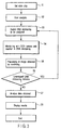
- the method of the present invention will be described with reference to the flow chart in FIG. 5.
- the apparatus described above as the embodiment of the present invention is configured so that dispensation and agitation of a liquid as well as control and measurement of temperature can always be executed on a reaction element placed on the stage. Accordingly, any type of reaction system can be easily established using a small space. Therefore, the apparatus of the present invention can constitute excellent means useful in any genetic examinations.
- At least one DNA microarray is small enough to allow imaging means such as a CCD camera or a scanning confocal camera to pick up an image of the entire DNA microarray. It is thus unnecessary to optically scan the plurality of separate probe spots in the DNA microarray to be measured. This makes it possible to simultaneously and continuously monitor reaction in each spot in the same DNA microarray. This is very advantageous in simultaneously examining multiple items.
- the present invention provides an apparatus that can consecutively execute a plurality of examinations on the same sample to obtain a plurality of detection results quickly or at an arbitrary time.
- analysis software that operates in such a measuring apparatus to analyze measurement data while checking the type of the reagent (for example, a nucleic acid probe and a nucleic acid primer) applied to each probe spot as well as each reaction condition against measurement data obtained for each reagent or for each reaction condition.
- the reagent for example, a nucleic acid probe and a nucleic acid primer
- the apparatus according to the present invention can simultaneously or sequentially cause plural types of reactions in the same probe spot.
- the apparatus according to the present invention may comprise new reading means for enabling the easy establishment of reaction conditions required to cause the plural types of reactions and the accurate reading and processing of a plurality of data obtained from the plural types of reactions.
- such reading means may execute the following:
- such reading means comprises storage means for storing data such as the examination item information, the monitored control conditions, and the measurement results and data, and data processing means such as a CPU which reads, compares, and checks data stored in the storage means and which executes required calculating processes.
- data processing means such as a CPU which reads, compares, and checks data stored in the storage means and which executes required calculating processes.
- Such new reading means and an apparatus comprising this reading means are also provided as embodiments of the present invention.
- this reading means for all the spots in the same visual field of the imaging means (for example, one visual field of a CCD), it is possible to store the results of reactions in the memory or the like without any mistakes, the results of reactions including the results of different types of reactions all or some of which are temporally superimposed on one another among a plurality of spots and the results of reactions occurring in at least one spot under different sets of reaction conditions. It is further possible to retrieve these results as required and output desired determination results.
- a chip As a container used to measure a gene, a chip is used which contains a porous filter having a plurality of genes immobilized on its surface, the genes being complementary to a target gene to be examined.
- a slide chip containing this porous filter is installed on a reaction section (incubator section) placed on a stage of a fluorescent microscope.
- the fluorescent microscope is configured so that its excitation light shutter and fluorescent cube as well as movement of the stage can be automatically controlled by a host computer.
- a device such as a CCD which photographs images is installed in the fluorescent microscope. Photographing timings for the device are also controlled by the host computer. Exposure time, image saving, and a cooling state can also be controlled by the computer.
- the incubator is provided with a pump used to transport a liquid and a heater or Peltier element used to control temperature. These devices can also be controlled by the host computer.
- a sample is dripped onto a measurement area of the chip. Then, the pump is used to move a reaction liquid so that the liquid moves forward and backward in channels. This accelerates the hybridization reaction.
- the solution leading to channels formed at the bottom of the incubator is moved.
- the excitation light shutter is opened.
- the imaging device such as a CCD camera or a scanning confocal camera is used to photograph a fluorescent image of the surface of the filter.
- the photographed image data is saved to a folder in a specified memory of the computer.
- a separately installed analysis program analyzes the results of measurements.
- the pump which facilitates hybridization
- the heater which varies the temperature of the chip, and as required, a pipetter system that varies the composition of the solution
- a target substance can be excited using different wavelengths corresponding to the types of fluorescent labels used for measurements so that images can be photographed at different fluorescent wavelengths. Consequently, even if a sample contains a substance labeled with a plurality of fluorescent dyes, for example, the fluorescence intensity ratio of two colors can be easily measured by automatically switching the filter cube.
- This examining apparatus can be used to sensitively detect the amount of expression of a gene such as C-myc or the like, which varies markedly with the cancerous transformation.
- the same apparatus can be used to quickly analyze two pathologically important variations in a gene, which controls complicated cellular functions inside a cell, that is, the amount of expression of the gene and mutation occurring inside the gene.
- the method used herein to prepare a sample is similar to that used for conventional gene examinations.
- the results obtained by this apparatus can be easily compared with gene information stored in a database such as GenBank which is laid open on the Internet.
- the level of hybridization of a target gene can be measured in real time while varying the conditions for the solution in the reaction section or varying the temperature condition.
- the use of the above apparatus according to the embodiment of the present invention has enabled the level of hybridization of a target gene to be measured in real time while varying the conditions for the solution in the reaction section or varying the temperature condition.
- the present invention has enabled the amount of expression of a target gene to be accurately measured.
- SNP single nucleotide polymorphism
- FIG. 6 shows an example of a slide chip used to measure the amounts of expression of c-myc, an estrogen receptor, and telomerase.
- FIG. 6(A) shows the arrangement of nucleic acid probes and housekeeping genes immobilized on respective probe spots on the slide chip. The numbers in the table are assigned to the respective probe spots. Probes and housekeeping genes for a plurality of genes including c-myc as shown in FIG. 6(A) are immobilized.
- FIG. 6(B) schematically shows probe spots which are provided in a DNA microarray and to which the respective numbers are assigned. A nucleic acid probe shown in association with a corresponding number in FIG. 6(A) and a housekeeping gene are immobilized to each probe spot. Each type of nucleic acid probe is immobilized to the corresponding probe spot by spotting thereof.
- FIGS. 6(C) and 6(D) are diagrams schematically showing the results of hybridization and analysis of the probes fixed in accordance with the pattern shown in FIG. 6(B) as well as a subject nucleic acid, according to the embodiment of the present invention.
- FIG. 6(C) shows results obtained from a sample from a normal subject.
- FIG. 6(D) shows results obtained from a sample from an abnormal subject.
- Optimum reaction conditions for each probe are established by using the above slide chip, varying the ambient temperature of the chip on which expression analysis has been executed as well as the composition of the solution, or setting the temperatures of the labeled nucleic acid in the sample and of the vicinity of the probe to be close to a TM (Melting Temperature). This makes it possible to analyze mutation occurring inside these genes.
- TM Melting Temperature
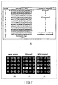
- FIG. 7 shows an example in which mutation occurring inside a tumor suppressor gene P53 is detected by comparing fluorescent spot intensities with each other which result from the probes having different nucleotide sequences.
- FIG. 7(A) shows the arrangement of the nucleic acid probes immobilized on the respective probe spots. The numbers in the table are assigned to the respective probe spots.
- the probes used for analysis are a plurality of arrangements associated with the tumor suppressor gene P53 as shown in FIG. 7(A), that is, sense including sense, antisense, sense including mismatch, and antisense including mismatch.
- FIG. 7(B) schematically shows probe spots which are provided in a DNA microarray and to which the respective numbers are assigned. The nucleic probes shown in FIG.
- FIGS. 7(C) and 7(D) are diagrams schematically showing the results of hybridization and analysis of the probes fixed in accordance with the pattern shown in FIG. 7(B) as well as a subject nucleic acid, according to the embodiment of the present invention.
- FIG. 7(C) shows results obtained from a sample from a normal subject.
- FIG. 7(D) shows results obtained from a sample from an abnormal subject.
- the detection of a gene and the analysis of the amount of expression described above can be continuously executed on one sample in one DNA microarray.
- the apparatus and method of the present invention thus enable the determination of the stage of cancerous transformation and the accurate prediction of malignancy, the likelihood of metastasis, or the differences in drug resistance among individual patients.
- the present invention can be considered to be as described below.
- the supplementary notes below are provided by focusing on the point that the present invention is not limited to genetic examinations depending on applications but can be widely provided to medical fields as a technology for monitoring various other biological reactions (enzyme reaction, antigen antibody reaction, metabolic reaction, biological exercise dynamism tests, and the like) at a high throughput.
- the temperatures of the plurality of fine reaction sections having their positions controlled are regulated so that it is possible to simultaneously obtain an image of a plurality of reaction sections involved in two or more different biological reactions.
- the imaging means picks up a plurality of images by performing temporally intermittent or continuous image pickup operations, some or all of different reaction processes can be simultaneously monitored.
- the zoom means sets a desired number of fine reaction sections within the same visual field to enable an image to be picked up at an optimum magnification.
- the calculating means processes data in real time by converting the results of reactions within the same visual field into desired output contents for each reaction section.
- the output means checks the results of calculations of image data from the plurality of reaction sections within the same visual field, on the basis of information on the regulated temperature. This enables the plurality of reaction sections to be sorted and arranged without any mistakes. Then, data on these reaction sections can be outputted in a form that can be easily checked by a user (for example, in print, displayed image, or transmitted data form).
- the present invention can be considered to be as described below.
- the temperature transmitting means regulates the temperatures of the plurality of reaction sections and of the fluid transferring means. Consequently, various fluids (for example, an examination sample and/or a reagent can be introduced into or conducted through each of the fine reaction sections under favorable reaction conditions. This serves to reduce the costs of temperature control and various liquid treatments, the time required for examinations, and the size of the apparatus. Furthermore, for biological reactions, it is possible to spatially efficiently arrange additional functions that are conventionally difficult to arrange simultaneously. Moreover, temperature transmission and/or fluid transfer can be executed simultaneously with the additional functions. Therefore, the single apparatus can be used to automate steps (for example, preparation of a sample, replacement of the reaction sections, dispensation, and various sensing operations and measurements) other than those for biological reactions.
- steps for example, preparation of a sample, replacement of the reaction sections, dispensation, and various sensing operations and measurements
- the use of the apparatus according to the embodiment of the present invention provides a gene examining apparatus and method which enables a plurality of genes to be examined easily and quickly.
- Such an apparatus and method enables the level of hybridization of a target gene to be measured in real time while varying the conditions for the solution in the reaction sections or varying the temperature condition. Therefore, the use of this apparatus enables the accurate measurement of whether or not a target gene is expressed and the amount of expression of this gene.
Landscapes
- Health & Medical Sciences (AREA)
- Chemical & Material Sciences (AREA)
- Analytical Chemistry (AREA)
- General Health & Medical Sciences (AREA)
- Hematology (AREA)
- Clinical Laboratory Science (AREA)
- Chemical Kinetics & Catalysis (AREA)
- Apparatus Associated With Microorganisms And Enzymes (AREA)
- Measuring Or Testing Involving Enzymes Or Micro-Organisms (AREA)
Abstract
The present invention relates to a gene examining
apparatus utilizing a computer, the apparatus
comprising (1) DNA microarrays in each of which a large
number of fine liquid accommodating sections are two-dimensionally
arranged so that openings of the fine
liquid accommodating sections are located on the same
plane, in which each of the liquid accommodating
sections can three-dimensionally accommodate a liquid,
and in which hybridization reaction occurs in the
liquid accommodating section between a target nucleic
acid already labeled with an optical marker substance
and the nucleic acid probe, and (2) a microscope
comprising a stage supporting the DNA microarrays set
forth in (1), a temperature regulating section that
regulates the temperature of each DNA microarray, and
imaging means for picking up an image of an optical
signal from the DNA microarray.
Description
The present invention relates to an apparatus that
detects the gene expression level and the presence or
absence of mutation, and a method of detecting a target
nucleic acid using this apparatus.
With the recent advancement of gene analysis
techniques, the gene sequences of a large number of
creatures including human beings have been revealed.
Furthermore, the causal relationships between analyzed
gene products and certain diseases have been gradually
elucidated.
The current method of examining genes comprises: a
step of extracting nucleic acids from a living sample;
a step of amplifying a target gene to be examined using
a nucleic acid amplifying method such as a PCR method
or a NASBA method; a step of labeling the nucleic acid
using a marker substance such as a radioisotope
(hereinafter referred to as an "RI") or a fluorescent
molecule; and a step of measuring the nucleotide
sequence of the labeled target gene or its
concentration.
Recently, many capillary electrophoresis
apparatuses have been used which can quickly treat a
large number of samples using a nucleic acid labeled
with fluorescence and a plurality of capillaries.
These apparatuses can analyze a large number of samples
in a time about one-third or a quarter of the time
required by methods using conventional electrophoresis
apparatuses.
Furthermore, in recent years, an examining method
has been developed which simultaneously examines a
plurality of genes using a DNA chip. The DNA chip is
manufactured by immobilizing a large number of cDNA
probes on the surface of a glass substrate, or by
utilizing a semiconductor manufacturing process to
synthesize a large number of oligo probes in a fine
area on a silicon. With either of these methods, the
DNA chip can simultaneously determine the presence of
plural types of target sequences contained in a sample.
The use of the DNA chip has made it possible to quickly
analyze the amount of expression of a large number of
genes as well as a plurality of mutations. Moreover,
on the basis of data obtained using the DNA chip, many
genes have been classified into a plurality of groups
(that is, clustering) or information on changes in
genes associated with development or differentiation
has been obtained. Gene information thus obtained is
utilized as an easily accessible database via the
Internet.
In general, an electrophoresis method or a
microarray method is used to examine the amount of
expression of genes and to analyze mutation. The
electrophoresis method requires a long time for
examinations and limits the types of examinations that
can be made at one time. On the other hand, a method
of analyzing a gene using a DNA chip allows a large
number of examinations to be made at one time but
requires a long time for examinations. Furthermore,
this method as a whole, requires many examining steps
and complicated procedures. Thus, disadvantageously,
the results of analysis based on this method are not
reproducible. To overcome these disadvantages, methods
have been developed which allow results obtained to be
appropriately reproduced and which are intended to
quickly finish examinations that are similar to those
of the method using a DNA chip. These methods include
one using a porous filter as carrier for a DNA chip
(PCT National Publication No. 1997-504864 and PCT
Domestic Publication No. 2000-515251), and one using an
electric force to force hybridization reaction (PCT
Domestic Publication No. 2001-501301). These methods
are disadvantageous in the use of an RI or the
necessity of a membrane filter. The method of using an
electric force to force hybridization reaction requires
the provision of, for example, a mechanism that
strictly controls the voltage in a chip. Thus, these
methods cannot meet clinical demands for quick and easy
examinations of genes.
For multifactor diseases such as cancer, diabetes,
and hypertension which are caused by a combination of a
plurality of gene defects and environmental factors,
more accurate diagnoses can be made by analyzing
defects in a plurality of genes in various manners and
further analyzing external environmental factors. In
actual chemotherapy, it is also necessary to accurately
predetermine a patient's sensitivity (also construed as
the patient's constitution) to an administered drug in
order to avoid the side effects of the drug and to
improve the results of the treatment. Moreover, when
an advanced gene therapy is executed using a P53 gene
or the like, it is necessary to accurately pre-analyze
genetic information such as the amount of expression of
a oncogene and/or a antioncogene in the patient's body,
whether or not mutation is present, or the conditions
of the signaling among cells.
Under these circumstances, a gene examining system
is desired to be developed which can easily and quickly
examine a plurality of genes.
All the cited documents and patent publications
disclosed in the specification are incorporated herein
by reference.
It is an object of the present invention to
provide a gene examining apparatus that can easily and
quickly examine a plurality of genes and a method of
detecting a target nucleic acid using this gene
examining apparatus.
According to a first embodiment of the present
invention as one aspect of it, there is provided a gene
examining apparatus utilizing a computer, the apparatus
comprising:
According to a further aspect of the present
invention, there is provided a method of examining a
gene using the apparatus set forth in the first
embodiment, the method comprising;
According to an aspect of the present invention,
an apparatus is provided which can easily detect the
expression level of a gene from one subject and the
presence of mutation in the gene in a short time.
Description will be given of the basic principle
of a detection method implemented by the apparatus
according to an embodiment of the present invention.
This method uses a nucleic acid immobilized on a
substrate and having a known sequence, to detect a
nucleic acid strand contained in a subject and having a
particular sequence. The apparatus according to the
embodiment of the present invention conceptually
comprises a single strand nucleic acid (that is, a
nucleic acid probe) as a reagent immobilized on a
substrate. In operation, the immobilized nucleic acid
probe is contacted with a nucleic acid contained in a
sample and labeled with an optical marker substance.
If the nucleic acid contained in the sample has a
sequence complementary to the nucleic acid probe, it is
hybridized with the nucleic acid. Thus, a double
strand is formed and the nucleic acid is captured on
the substrate. Subsequently, by carrying out washing
to remove an nonreacted nucleic acid strand and
detecting the label of the nucleic acid, it is possible
to detect the presence of a nucleic acid having a
sequence complementary to the nucleic acid probe.
Here, the "optical marker substance" means a
fluorescent substance, a chemical light-emitting
substance, a biological light-emitting substance, and
any other substances that can emit light as an
observable signal.
An embodiment of the apparatus of the present
invention will be described with reference to the block
diagram shown in FIG. 1. The apparatus according to
the embodiment of the present invention is a gene
examining apparatus utilizing a computer.
A gene examining apparatus 1 comprises a
microscope 3 used to microscopically observe an event
in DMA microarrays 22 in which a sample is caused to
react, a stage 4 provided in the microscope 3 in order
to support a reaction block 100 that accommodates a
slide chip 2 comprising the DNA microarrays 22, imaging
means 5 for picking up an image of a signal from an
optical marker substance in each DNA microarray 22, the
substance being observed using the microscope 3, an XY
stage controller 7 that controls a motor driver 6
connected to the stage 4 in order to change the
position of a visual field observed using the
microscope 3, a zoom means driving device 18 that
drivingly controls zoom means 17 for enlarging and/or
reducing the visual field observed using the microscope
3, a pump driver 8 that transports a fluid via a joint
section connected to the DNA microarrays 22, a temperature
controller 9 that regulates the temperature of
each DNA microarray via a heater section 101 arranged
in contact with the DNA microarray 22, and a computer
10 connected directly or indirectly to all the devices
included in the gene examining apparatus 1 to
integrally control them.
The joint section 120 is connected to the DNA
microarrays 22 in the reaction block 100 so as not to
leak the fluid contained in the DNA microarrays 22 to
the exterior. A terminal of the joint section 120 is
connected to the pump driver via a tube. The pump
driver 8 is in turn connected to a reagent holding
section containing a desired reagent and the like. The
pump driver 8 moves a fluid into and out of the DNA
microarrays in response to instructions from the
computer 10 in accordance with an analysis program.
The heater section 101 is arranged between the
slide chip and the stage 4. The heater section is
connected to the temperature controller 9 and has its
temperature regulated by the temperature controller in
accordance with instructions from the computer 10.
Preferably, the heater section 101 comprises a number
of heaters the number of which corresponds to the
number of DNA microarrays 22 of the reaction block 100
and which can be individually controlled by the
controller 9.
The computer 10 includes components provided in
common computers. Although not shown in FIG. 1, the
components provided in the computer 10 may include, for
example, at least a CPU 11 (Central Processing Unit)
that is a main control section integrally controlling
each section of the computer 10, a memory 12 that
stores various programs on which control by the CPU 11
is based and files for image data or the like which is
to be displayed, a RAM (Random Access Memory) 13 that
temporarily stores, for example, the results of
execution by the CPU 11, an image processing section 14
that generates image data in accordance with instructions
from the CPU 11 based on a program or the like,
an input section 15 such as a keyboard and a mouse
which is used by an operator, for example, a user to
input information into the computer 10, and a display
section 16 such as a display or a printer which
displays information in accordance with instructions
from the computer 10.
Information obtained by the imaging means is
transmitted to the image processing section 14. The
image processing section 14 processes the information
in response to instructions from the CPU 11 in
accordance with the analysis program stored in the
memory 12. The information is thus digitized as the
intensity of an optical signal emitted by an optical
marker substance, for example, a fluorescence
intensity.
The computer that can be used in the present
invention may be any electronic computer that can be
commonly used.
If for example, the optical marker substance is a
fluorescent substance, the microscope that can be used
in the present invention may be any fluorescent
microscope that is commonly used. The microscope may
be, for example, the fluorescent microscope AX-70 or
BX-42TFR manufactured by Olympus. However, the present
invention is not limited to these microscopes.
The imaging means that can be used in the present
invention has only to be well-known means that can be
used to pick up an image of a common optical signal
corresponding to the type of the optical marker
substance. If for example, the optical marker
substance is a fluorescent substance, the imaging means
is means for picking up a fluorescent image. Such
imaging means includes, for example, a CCD (Charge
Coupled Device) and a scanning confocal camera.
However, the present invention is not limited these
imaging means.
The CCD camera has only to be one commonly used.
For example, it may be a common digital camera such as
a MegaPlus CCD camera manufactured by Kodac or a Cool
Pix camera manufactured by Photometric. The scanning
confocal camera also has only to be one commonly used.
The temperature regulating section regulating the
temperature of each DNA microarray 22 may include a
heating element (for example, an electric heater, an
electromagnetic heater, a water bath, an air bath, and
Peltier element) that contacts directly or indirectly
with the slide chip 2, comprising the DNA microarrays
22, to transmit heat to the slide chip 2, a sensor
that sense the temperature of the slide chip 2, and a
temperature controller that controls the heating of the
heating element in accordance with control provided by
the computer and information transmitted by the sensor.
The computer may be connected to the Integrated
Services Digital Network (hereinafter referred to as
the "ISDN") or to a telephone line via a modem.
The stage 4 provided in the above embodiment can
be moved in an X and Y directions by the XY stage
controller 7 as described above. However, changes in
visual field are not limited to such movement of the
stage. The visual field may be changed, for example,
by the imaging means itself or using various scanning
mechanisms such as means for changing an optical path
joining the imaging means 5 and the microarrays 22
together.
FIGS. 2(A) and 2(B) show an embodiment of the DNA
microarrays 22 used in the present invention.
FIG. 2(A) is a plan view of the slide chip 2. The
slide chip 2 comprises four DNA microarrays 22 in which
reaction occurs. FIG. 2(B) is a sectional view of the
slide chip 2.
As shown in FIG. 2(B), the slide chip 2 comprises
a filter 19 composed of a porous material and a support
plate 20 that supports the filter 19. Channels
contained in the filter 19 preferably have branches.
However, the channels need not necessarily have
branches. The support plate 20 is composed of two
members, support plates 20a and 20b. These two members
are joined together while sandwiching the filter 19
between them, to constitute the slide chip 2. As shown
in FIG. 2(B), according to an embodiment of the present
invention, the support plates 20a and 20b, located over
and under the filter 19 have openings 21 that define
the DNA microarrays 22.
As shown in FIG. 2(B), the filter 19, located
between the two support plates 20a and 20b, is composed
of one piece containing all the four DNA microarrays.
The filter 19 is flat and extends two-dimensionally
over an area including all the four DNA microarrays.
The support plate 20 is preferably composed of a
shielding member and more preferably of a dark black
member. Preferably, the supports 20a and 20b are
joined together while sandwiching the filter 19 between
them.
The filter 19 may be composed of any material
provided that it is not damaged within the range of
temperature control carried out in the filter.
The DNA microarrays 22 refer to parts of the
filter 19 that are exposed from the openings 21 formed
in the support plate 20. The channels contained in the
filter 19 may or may not have branches, but preferably
have branches. All the channels 24 provided in the
filter 19 are preferably arranged at almost equal
intervals. However, all the channels 24 may be
arranged at almost equal intervals at least in the
microarrays 22, exposed from the support plate 20.
Provided that a filter 19 is manufactured which
has a constant thickness and which comprises channels
24 the shapes of which are made as equal to one another
as possible, the channels have an almost uniform
volume. Alternatively, the filter 19 may be
sufficiently thin and each channel 24 may have a
sufficiently small diameter. Then, a required amount
of sample and/or reagent can be distributed to a large
number of channels. By forming channels the number of
which is required to accommodate a desired amount of
liquid, per particular area of one surface of the
filter, and supplying a sample and/or a reagent to this
predetermined area, stable analysis can be executed
within the porous film of the filter 19. For example,
the temperature of the liquid in the chambers can be
increased or reduced by contacting one or both surfaces
of the filter 19 with a gas having a controlled desired
temperature. On the other hand, if analysis is
executed by using a reaction container composed of
one elongate tubular capillary to accommodate a
predetermined amount of sample and/or reagent in
the capillary, a material having as high a heat
conductivity as possible can be selected to construct
the capillary. To accomplish appropriate optical
measurements, the capillary must be shaped to have a
flat surface.
FIG. 2(C) shown immediately above the slide chip 2
in FIG. 2(A) is an enlarged view of the microarray 22
(also referred to as the "DNA microarray"). The
plurality of channels 24 are present in the microarray
22. A nucleic acid probe is immobilized on the inner
wall of some of the channels in the microarray 22. An
area to which the nucleic acid probes are fixed is a
probe spot 23 (also simply referred to as a "spot").
As shown in FIG. 2(c), each DNA microarray 22 comprises
a plurality of probe spots 23.
FIG. 2(D) is an enlarged view of the probe spots
and their periphery. In FIG. 2(D), for convenience,
the channels 24 included in each probe spot 23 are
shown by black circles. The channels 24 to which no
probes are fixed are shown by white circles. The probe
spot 23 is an area composed of the channels 24
comprising a plurality of probes. Normally, one probe
spot 23 may be considered to be a minimum unit to which
one type of probe is fixed, for the channels 24 present
in parts of the filter 19 that are exposed from the
support plate 20. That is, the probe has only to be
immobilized on the inner wall surface of each of the
channels included in the probe spot 23.
Although FIGS. 2(C) and 2(D) show generally
circular areas, the contour of the probe spot 23 may be
a general circle, a general rectangle, or a polygon.
The same probe may be immobilized on a plurality
of probe spots 23 as desired. Alternatively, the inner
wall of each channel may be subjected to surface
treatment to adjust frictional resistance to a fluid or
the ability of the probes to adsorb a reagent.
The size of the present slide chip is 0.5 to
20.0 cm × 0.5 to 20 cm × 0.01 to 1.0 cm, preferably
1.0 to 10.0 cm × 1.0 to 10.0 cm × 0.05 to 0.5 cm.
Particularly preferably, it may be 3.0 to 8.0 cm × 3.0
to 8.0 cm × 0.05 to 0.2 cm. An example of an actually
produced slide chip has a size of about 7.5 cm × about
2.5 cm × about 0.1 cm.
The present microarray is 3.0 mm2 to 16 mm2,
preferably 12.0 to 400 mm2, particularly preferably
20.0 to 100.0 mm2. Circular microarrays on the
actually produced slide chip have a diameter of about
6 mm (about 28.3 mm2).
The probe spot included in the present DNA
microarray has a diameter of 100 to 300 µm, preferably
120 µm. Ten to thousand probe spots, preferably 400
probe spots may be provided per DNA microarray. The
porous filter has only to have an openness of 0.05 to
0.5 µm, preferably 0.2 µm. Different types of nucleic
acid probes may be immobilized on the respective probe
spots.
The term "DNA microarray" as used herein refers to
one reaction unit in which one type of reaction occurs.
The DNA microarray comprises a plurality of probe spots
23 each composed of a plurality of channels 24 to which
the respective nucleic probes are fixed. In a conventional
DNA chip, probes are immobilized on a surface of
a slide glass to form a two-dimensionally extending
reaction area. In contrast to such a conventional DNA
chip, the DNA microarray of the present invention has
not only a two-dimensional extension over the surface
of the substrate but also an extension perpendicular to
the surface (that is, extending in the direction of the
thickness of the substrate). The DNA microarray of the
present invention thus has a three-dimensionally
extended reaction area.
An example of a DNA microarray preferably used in
the present invention may be the device described in
PCT National Publication No. 2000-515251 or the
micromachined flow-through porous apparatus described
in PCT National Publication No. 1997-504864.
FIG. 2 shows the slide chip 2 comprising the four
microarrays 22. However, more or less than four DNA
microarrays may be provided. In the description
herein, the slide chip 2 comprises the four DNA
microarrays 22 as a preferable embodiment. However,
the present invention is not limited to this
embodiment. It is obvious to those skilled in the art
that changing the number of DNA microarrays involves
changes in other arrangements of the apparatus and in
procedures to be executed. Such changes are included
in the scope of the present invention.
If for example, a slide chip 2 comprising four DNA
microarrays 22 is used, different subjects may be
examined using the respective DNA microarrays.
Alternatively, one chip may be used to allow one
subject to undergo four types of analysis, for example,
the analysis of mutation of an oncogene, expression
analysis, the analysis of a drug resistant gene, and
determination of the expression pattern of an
intracellular signaling gene.
It is possible to appropriately change the number
and arrangement density and pattern of channels
included per microarray 22 as well as the size, for
example, the diameter of the channel. The shape and /
diameter of one channel may be varied between different
areas of the microarray 22.
In the above embodiment, the filter 19 is a flat
member appearing to have a two-dimensionally extending
plane as well as a thickness in a direction perpendicular
to the plane. However, the filter used
according to the present invention is not limited to
such a shape. Furthermore, the channels need not be
arranged perpendicularly to the flat member.
The term "nucleic acid probe" as used herein
generally refers to polynucleotide or oligonucleotide,
consisting of about 10 or more to about 100 or less
nucleic acids. This nucleic probe generally has only
to be able to be used to detect nucleic acids by
hybridization.
The probe may be any desired nucleic acid, for
example, oligonucleotide corresponding to an oncogene
such as P53 or c-myc, oligonucleotide corresponding to
an antioncogene, oligonucleotide corresponding to a
disease-related gene or a sensitive gene, or
oligonucleotide corresponding to a sequence containing
a polymorphous.
Besides the genes to be analyzed, use may be made
of the probes for housekeeping genes such as β globlin
or actin, which can be used to measure the steady state
of a sample. Using the amount of such housekeeping
genes as the reference amount of genes in a cell, it is
allowable to measure the amount of expression of an
actual oncogene, antioncogene, or drug resistant gene.
This makes it possible to more accurately measure the
amount of expression of genes in a cell.
The term "target nucleic acid" as used herein
refers to a nucleic acid contained in a sample and
which is to be detected.
According to the embodiment of the present
invention, if analysis is executed using the slide chip
2 in which the above DNA microarrays 22 are arranged,
the slide chip 2 contains a plurality of DNA
microarrays 22. The DNA microarray 22 comprises a
plurality of probe spots 23 each comprising a plurality
of channels 24 each having a three-dimensional space in
which a small amount of liquid can be accommodated.
The channel 24 has a three-dimensional space, but all
the openings, through which a fluid is moved into and
out of the channels 24, are two-dimensionally arranged
on the same plane. Accordingly, in a plane obtained
when the slide chip 2 is viewed from above, each probe
spot 23 appears to have a very small area. However, it
actually comprises a three-dimensional space extending
from the small-area opening.
For example, by varying conditions for each probe
spot (for example, varying the type of probe fixed or
varying surface treatment), very many pieces of
information can be sufficiently sensitively obtained
from one fine DNA microarray. Furthermore, temperature
control or measurement data analysis can be executed
for each DNA microarray. The results of reaction can
be quickly obtained from the small apparatus for
multiple items. Alternatively, temperature control or
measurement data analysis can be executed for each
probe spot. In this case, the results of reaction can
be quickly obtained for multiple items.
In the above described embodiment of the present
invention, the example is shown in which the probe is
immobilized on the inner wall of each channel in
the porous film. The probe need not necessarily
immobilized. The present invention is also applicable
to a reaction system in which a reagent is not
immobilized on the inner wall of the channel in the
porous film but is allowed to float freely in a liquid
phase or is freely suspended in it. This system is
similar to the above described embodiment except that
the probe is not immobilized. In this case, the "probe
spot" can be referred to as a "reaction spot".
However, the "reaction spot" is included and described
as an embodiment of the probe spot.
The DNA microarray 22 according to the embodiment
of the present invention has the three-dimensional
structure described above. Thus, even in the same
visual field of the microscope, the DNA microarray 22
has a surface area about 300 to about 800 times as
large as that of a conventional planar DNA chip and in
a practical range, about 500 times as large. Moreover,
in the DNA microarray 22 according to the embodiment of
the present invention, a fluid such as a sample flows
along the inner wall of a fine filter structure such as
the one described above. Thus, with the DNA microarray
22, reaction rises significantly quickly compared to
the conventional planar DNA chip. Detection
sensitivities about 100 times higher, or about 10 to
50 times higher than that obtained with the conventional
planar DNA chip are obtained in about 5 or about
15 minutes, respectively, after the start of reaction.
Under these advantageous conditions, a large number of
fine liquid accommodating sections that can three-dimensionally
accommodate a liquid are two-dimensionally
arranged so that their openings are
located on the same plane. Accordingly, by using a DNA
microarray to cause hybridization reaction between a
target nucleic acid already labeled with an optical
marker substance and the nucleic acid probe, a large
number of separate reaction areas (probe spots) can be
arranged within a visual field smaller than that
required in the prior art. At a low magnification, the
imaging means provided with the zoom means 17 as shown
in FIG. 1 can preferably command an entire view of a
large number of reaction areas. At a large magnification,
the imaging means can preferably observe a
desired limited number of reaction areas by enlarging
them. The zoom means 17 preferably comprises an
optical-path changing mechanism based on a galvano
mirror. It is thus possible to position a visual field
for image pickup so that for an area on the array which
contains a large number of reaction areas within the
range of the visual field at a reduced magnification,
the visual field accommodates a desired number of
arbitrary reaction areas at a desired magnification.
Furthermore, the zoom means driving device 18 enlarges
and/or reduces the imaging visual field to automatically
measure specified desired reaction areas and to
instantaneously display target reaction areas on the
display in response to an operator's instruction.
The reaction block 100 has at least one reaction
liquid accommodating section, preferably, a plurality
of reaction liquid accommodating sections, for example,
four reaction liquid accommodating sections as shown in
FIG. 8. Each of the reaction liquid accommodating
sections has an upper well opened in the top surface of
the reaction block 100, a lower well 112 located under
the upper well 152, and a flow passage that allows the
lower well 112 to communicate with an external space.
In the subsequent description, the reaction block
100 is not limited to the one described above but is
assumed to have four reaction liquid accommodating
sections.
The reaction block 100 further has the DNA
microarray 22 arranged between the upper well 152 and
the lower well 112 as a reaction section. In other
words, the upper well 152 and the lower well 112 are
separated from each other by the DNA microarray 22,
composed of the filter 19. The DNA microarray 22 has
the nucleic acid probes each immobilized on the inner
wall of the porous member as described in FIG. 2.
The reaction block 100 has the upper well 152
opened in its top surface. The upper well 152 enables
a reaction section 132 to be optically observed from
above the reaction block 100.
To obtain the above described structure, the
reaction block 100 has a base 110 and an upper plate
150 both constituting a container main body, and an
alumina porous member 130 having the reaction section
132 as shown in FIG. 9. The base 110 and the upper
plate 150 are made of, for example, polycarbonate and
are fixed to each other via the alumina porous member
130 using an arbitrary appropriate technique such as
screwing or adhesion. The material for the reaction
block 100 according to the embodiment of the present
invention is not limited to polycarbonate. However,
any material may be used provided that it has a high
pressure resistance and a high heat conduction level.
In this case, as shown in FIG. 9, packing members
such as O rings 155 and 117 are preferably used for
each upper well 152 and for each lower well 112,
respectively, to ensure air tightness. The air
tightness is preferably ensured for each well using the
packing members because it is possible to avoid not
only the adverse effects of an external space but also
adverse effects that may be produced between the wells.
The upper plate 150 has a tapered through-hole
defining the upper well 152 and a groove 154 extending
from the through-hole (upper well 152) through the top
surface of the upper plate 150.
The base 110 has a concave portion defining the
lower well 112 and the flow passage 114 that allows the
concave portion (lower well 112) to communicate with
the external space. More specifically, the base 110
has a flat side 118, and the flow passage 114 extends
from a bottom surface of the concave portion (lower
well 112) and terminates with a joint section 120 at
the side 118 of the base 110. In the side 118 (that
is, a terminal surface of the flow passage), the base
110 further has an O ring 119 disposed in a ring groove
116 surrounding an opening end of the flow passage 114.
In this example, four joint sections 120 are linked to
separate tubes in turn connected to the pump driver 8.
The base 110 may further have one or more
projections formed on the bottom surface of the concave
portion (lower well 112) to suppress the deformation of
the reaction in order to avoid damage to the reaction
section 132, that is, its tear or breakage. The
projections may be shaped like pins or plates.
As described previously, the reaction liquid
accommodating section is composed of the upper well
152, the lower well 112, and the flow passage 114 as
shown in FIG. 9. The sum of the volumes of the lower
well 112 and flow passage 114 is larger than the volume
of the upper well 152. Accordingly, the lower well 112
and the flow passage 114 can accommodate the total
amount of reaction liquid initially filled into the
upper well 152. The flow channel 114 has an extended
portion, that is, a so-called reservoir, in order to
obtain a sufficient volume.
To suppress the evaporation of the reaction
liquid, the reaction block 100 preferably has a flat
top surface and an observation window 410 that resists
pressure and heat is placed on the top surface so that
there is a small clearance above the top surface of the
DNA microarray 22. The observation window 410 is
arranged so as to cover the entire upper well 152 while
partly covering the groove 154. Covering the entire
upper well 152 minimizes the evaporation of the
reaction liquid. The observation window that can be
used in the embodiment of the present invention may be
formed of, for example, glass, polymethylpentene, and
polycarbonate.
In the embodiment of the present invention, an
examination is started by the operator setting, on the
stage 4, the closed reaction block 100 integrated by
accommodating a sample and a reagent, reaction
components, in each DNA microarray 22 and attaching the
observation window 410 to the reaction block 100.
Now, description will be given of software
required to allow the functioning of the above
described gene examining apparatus according to the
embodiment of the present invention. Furthermore,
description will be given of an example in which a
fluorescent substance is used as an optical marker
substance according to the embodiment of the present
invention. However, the present invention is not
limited to this aspect.
The memory 21 provided in the computer 10, shown
in FIG. 1, stores, for example, programs used to
control the present apparatus via the CPU 11,
information such as tables which is retrieved by the
CPU 11 and used as bases for control and
determinations, and image data utilized to display
results obtained.
For example, an analysis program is used to carry
out gene analysis and may contain commands relating to
the procedure of operations required to allow the
computer to execute the analysis.
For example, a reaction progress program may
contain commands relating to the procedure of
operations required to allow the computer to cause
reaction in the DNA microarrays 22. The reaction
progress program may pre-contain commands relating to a
reagent selected for hybridization, the amount of
reagent used, reaction conditions such as a reaction
time and a reaction temperature, the number of pumping
operations and the time required for the pumping, and
conditions for liquid transportation and agitation at
the start of the pumping. Alternatively, the reaction
progress program may contain commands instructing the
operator to input these pieces of information at the
start of the analysis. Alternatively, these reaction
conditions may be stored in the memory 12 as a reaction
condition program that is different from the procedure
of reaction.
The above programs are examples of programs used
to control the present apparatus. However, other
required programs may be stored in the memory 12.
For example, a gene correspondence table may
specify the associations between fluorescence
intensities obtained and reaction conditions and the
amount of expression of genes, expressed genes,
mutation of genes, and the like.
Operations of the present embodiment will be
described with reference to the flow chart shown in
FIG. 3. Furthermore, description will be given of an
example in which a fluorescent substance is used as an
optical marker substance according to the embodiment of
the present invention. However, the present invention
is not limited to this aspect.
In the above description, the information on the
reaction conditions inputted by the operator in S2 may
be, for example, the reaction temperature, the reaction
time, the number of reactions, and the selected
reagent. Alternatively, the information may be
contained in the reaction progress program or reaction
condition program pre-stored in the memory 12 rather
than being inputted by the operator in S2.
In the above described example of a procedure, the
DNA microarrays 22 are individually analyzed. However,
all the DNA microarrays 22 may be simultaneously
analyzed. Furthermore, in the above description, the
DNA microarray 22 to be analyzed is automatically
selected in the order of the already assigned
recognition numbers. However, for each analysis, the
operator may select the DNA microarray 22 to be
analyzed and input an instruction on the execution of
desired analysis through the input section 15.
Furthermore, by connecting the computer to the
ISDN or a telephone line, the results obtained by the
analysis can be compared with information obtained by
searching a desired genome database or nucleotide
sequence database. This procedure may be set so that
on the basis of a comparison program stored in the
memory 12, the CPU 11 searches a database and compares
the results of the search with the results obtained by
the apparatus for identification.
The reaction in (S4) will be further described
with reference to FIG. 4.
Example of analyses that can be executed using the
apparatus of the present invention include clinical
therapeutic and diagnostic analyses as well as various
gene analyses even in non-clinical basic research, such
as detection of mutation of an oncogene or the like in
the subject, analysis of the expression of a gene in
the Subject, analysis of the expression of a drug
resistant gene, determination of the gene type of a
disease-related or sensitivity gene in the subject, and
determination of the expression pattern of an
intracellular signaling gene in the subject.
In general, the sample used for gene examinations
may be, in the case of human beings, blood, a cultured
cell, or a living tissue such as a cell or tissue which
is obtained during biopsy or an operation.
For example, a tissue section endoscopically
obtained is fixed to a slide glass, stained, and
pathologically examined. Then, only a part of the
tissue which corresponds to the cancer focus is
collected from the slide glass using the laser capture
system LCS200, which is a microdissection system
manufactured by Olympus. Then, this part can be used
as a sample.
Before the present apparatus is used to make
analysis, the living sample thus obtained is treated
with a nucleic acid extracting reagent utilizing a
phenol and chloroform method, a microcolumn method, or
a magnetic particle method, or the like to extract a
DNA and/or RNA. Moreover, the extracted DNA and/or RNA
is subjected to gene amplification using a PCR method,
an RT-PCR method, a T7 amplifying method, or the like.
However, if the sample has a large amount of nucleic
acid, a cDNA may be prepared without carrying out gene
amplification. However, in any case, the composition
of the reagent is preferably optimized so that a marker
substance, for example, any fluorescent marker
substance such as FITC, rhodamine, Cy3, or Cy5 is added
to a 5' end of a primer or any site in a synthesized
nucleotide.
The preparation of such a sample used for analysis
may be generally carried out using a well-known method
as descried in, for example, "DNA Microarray and Latest
PCR Method" (separate volume of Cell Engineering;
Genome Science Series 1, Shujunsha, published on March
16, 2000).
After the fluorescent labeling has been carried
out, the operator may use a pipette to dispense the
manually prepared sample to the DNA microarray.
Subsequently, the above described apparatus may be used
to execute analysis.
As described above, the inventors have completed a
gene examining system as an embodiment of the present
invention in which the a reaction section comprises
three-dimensional DNA microarrays expected to quickly
and efficiently accomplish hybridization using a filter
and in which a pump for solution control, a temperature
regulating system for temperature regulation, and a
sensitive fluorescent detecting device are combined
with an imaging device controlled by a computer.
Description will be given below of an example in which
fluorescence is used as an optical signal. However,
the present invention is not limited to this aspect.
A method of analyzing a gene using such a system
is included in the scope of the present invention. The
method of the present invention will be described with
reference to the flow chart in FIG. 5.
In this example, two reactions are consecutively
caused using respective sets of reaction conditions.
However, it is possible to increase the number of
consecutive reactions and the number of measurements of
the fluorescence intensity. In this case, the steps
from (Sf) to (Sg) may be repeated a required number of
times.
The apparatus described above as the embodiment of
the present invention is configured so that dispensation
and agitation of a liquid as well as control and
measurement of temperature can always be executed on a
reaction element placed on the stage. Accordingly, any
type of reaction system can be easily established using
a small space. Therefore, the apparatus of the present
invention can constitute excellent means useful in any
genetic examinations.
Furthermore, according to the present invention,
at least one DNA microarray is small enough to allow
imaging means such as a CCD camera or a scanning
confocal camera to pick up an image of the entire DNA
microarray. It is thus unnecessary to optically scan
the plurality of separate probe spots in the DNA
microarray to be measured. This makes it possible to
simultaneously and continuously monitor reaction in
each spot in the same DNA microarray. This is very
advantageous in simultaneously examining multiple
items.
According to further aspect of the present
invention, the present invention provides an apparatus
that can consecutively execute a plurality of
examinations on the same sample to obtain a plurality
of detection results quickly or at an arbitrary time.
According to the present invention, there is
provided analysis software that operates in such a
measuring apparatus to analyze measurement data while
checking the type of the reagent (for example, a
nucleic acid probe and a nucleic acid primer) applied
to each probe spot as well as each reaction condition
against measurement data obtained for each reagent or
for each reaction condition.
In particular, the apparatus according to the
present invention can simultaneously or sequentially
cause plural types of reactions in the same probe spot.
Accordingly, the apparatus according to the present
invention may comprise new reading means for enabling
the easy establishment of reaction conditions required
to cause the plural types of reactions and the accurate
reading and processing of a plurality of data obtained
from the plural types of reactions.
For example, such reading means may execute the
following:
Accordingly, such reading means comprises storage
means for storing data such as the examination item
information, the monitored control conditions, and the
measurement results and data, and data processing means
such as a CPU which reads, compares, and checks data
stored in the storage means and which executes required
calculating processes.
Such new reading means and an apparatus comprising
this reading means are also provided as embodiments of
the present invention.
According to this reading means, for all the spots
in the same visual field of the imaging means (for
example, one visual field of a CCD), it is possible to
store the results of reactions in the memory or the
like without any mistakes, the results of reactions
including the results of different types of reactions
all or some of which are temporally superimposed on one
another among a plurality of spots and the results of
reactions occurring in at least one spot under
different sets of reaction conditions. It is further
possible to retrieve these results as required and
output desired determination results.
In the above described embodiment, description has
been given mainly of the example in which a fluorescent
material is used as an optical marker substance.
However, the present invention is not limited to this
substance. That is, the optical marker substance used
can be varied as required. Accordingly, if such a
light emitting substance as described above is used,
the required parts of the embodiment may be
correspondingly changed. The changed embodiment is
still included in the scope of the present invention.
The embodiment of the present invention has been
described in detail. However, the above detailed
description and drawings are intended to illustrate the
embodiment and are thus not intended to limit the
present invention. The present invention includes
various improved or varied inventions based on various
equivalents and the present obvious technical
knowledge.
Gene analysis is carried out using the embodiment
of the present invention shown in FIGS. 1 and 2.
As a container used to measure a gene, a chip is
used which contains a porous filter having a plurality
of genes immobilized on its surface, the genes being
complementary to a target gene to be examined. A slide
chip containing this porous filter is installed on a
reaction section (incubator section) placed on a stage
of a fluorescent microscope. The fluorescent
microscope is configured so that its excitation light
shutter and fluorescent cube as well as movement of the
stage can be automatically controlled by a host
computer. A device such as a CCD which photographs
images is installed in the fluorescent microscope.
Photographing timings for the device are also
controlled by the host computer. Exposure time, image
saving, and a cooling state can also be controlled by
the computer. Furthermore, the incubator is provided
with a pump used to transport a liquid and a heater or
Peltier element used to control temperature. These
devices can also be controlled by the host computer.
A sample is dripped onto a measurement area of the
chip. Then, the pump is used to move a reaction liquid
so that the liquid moves forward and backward in
channels. This accelerates the hybridization reaction.
The solution leading to channels formed at the bottom
of the incubator is moved. When the level of the
reaction liquid reaches the top surface of the filter,
the excitation light shutter is opened. Then, the
imaging device such as a CCD camera or a scanning
confocal camera is used to photograph a fluorescent
image of the surface of the filter. The photographed
image data is saved to a folder in a specified memory
of the computer. A separately installed analysis
program analyzes the results of measurements.
By thus arranging, around the periphery of the
incubator, the pump, which facilitates hybridization,
the heater, which varies the temperature of the chip,
and as required, a pipetter system that varies the
composition of the solution, it is possible to use the
single examining system to continuously obtain patterns
of hybridization at various temperatures and in various
solution conditions. Furthermore, a target substance
can be excited using different wavelengths corresponding
to the types of fluorescent labels used for
measurements so that images can be photographed at
different fluorescent wavelengths. Consequently, even
if a sample contains a substance labeled with a
plurality of fluorescent dyes, for example, the
fluorescence intensity ratio of two colors can be
easily measured by automatically switching the filter
cube. On the basis of the fluorescence intensities of
the spots thus obtained, the amounts of the probes
immobilized on the chip surface and of the hybridized
target gene are analyzed. This examining apparatus can
be used to sensitively detect the amount of expression
of a gene such as C-myc or the like, which varies
markedly with the cancerous transformation.
Furthermore, by analyzing the pattern of a
variation in the fluorescence intensity of the
fluorescent spot caused by a variation in the
temperature of the incubator, it is possible to detect
mutation of a gene such as K-Pas or P53 which
significantly contributes to cancerous transformation.
Thus, the same apparatus can be used to quickly analyze
two pathologically important variations in a gene,
which controls complicated cellular functions inside a
cell, that is, the amount of expression of the gene and
mutation occurring inside the gene. The method used
herein to prepare a sample is similar to that used for
conventional gene examinations. The results obtained
by this apparatus can be easily compared with gene
information stored in a database such as GenBank which
is laid open on the Internet.
Using the apparatus according to the embodiment of
the present invention, the level of hybridization of a
target gene can be measured in real time while varying
the conditions for the solution in the reaction section
or varying the temperature condition.
The use of the above apparatus according to the
embodiment of the present invention has enabled the
level of hybridization of a target gene to be measured
in real time while varying the conditions for the
solution in the reaction section or varying the
temperature condition. The present invention has
enabled the amount of expression of a target gene to be
accurately measured.
Furthermore, by automatically changing the
temperature of the microarray or the composition of
the solution in the reaction container after the
measurement of the amount of expression, it is possible
to forcedly vary the efficiency of hybridization among
different probes to detect the type of mutation
occurring in the target gene, for example, single
nucleotide polymorphism (hereinafter referred to as
"SNP"). The use of this system is expected to enable
the accurate prediction of the level of progress or
malignancy of cancer or the like, the possibility of
metastasis, or the stage of the disease.
It is also possible to simultaneously check the
amount of expression of a drug sensitive gene such as
P450 which affects the sensitivity to a drug as well as
SNPs, which affect activity. By thus checking defects
in a causal gene for a disease and defects in a gene
sensitive to a drug, it is possible to optimize the
type of a drug selected and the temperature in
accordance with a patient's constitution. Furthermore,
on the basis of information on gene defects obtained, a
gene can be accurately selected which is used for a
gene therapy expected to be very effective in the
future.
FIG. 6 shows an example of a slide chip used to
measure the amounts of expression of c-myc, an estrogen
receptor, and telomerase. FIG. 6(A) shows the
arrangement of nucleic acid probes and housekeeping
genes immobilized on respective probe spots on the
slide chip. The numbers in the table are assigned to
the respective probe spots. Probes and housekeeping
genes for a plurality of genes including c-myc as shown
in FIG. 6(A) are immobilized. FIG. 6(B) schematically
shows probe spots which are provided in a DNA
microarray and to which the respective numbers are
assigned. A nucleic acid probe shown in association
with a corresponding number in FIG. 6(A) and a
housekeeping gene are immobilized to each probe spot.
Each type of nucleic acid probe is immobilized to the
corresponding probe spot by spotting thereof.
FIGS. 6(C) and 6(D) are diagrams schematically
showing the results of hybridization and analysis of
the probes fixed in accordance with the pattern shown
in FIG. 6(B) as well as a subject nucleic acid,
according to the embodiment of the present invention.
FIG. 6(C) shows results obtained from a sample from a
normal subject. FIG. 6(D) shows results obtained from
a sample from an abnormal subject. By determining
whether fluorescence is present on the basis of these
results, it is possible to detect a gene expressed in
the subject.
Optimum reaction conditions for each probe are
established by using the above slide chip, varying the
ambient temperature of the chip on which expression
analysis has been executed as well as the composition
of the solution, or setting the temperatures of the
labeled nucleic acid in the sample and of the vicinity
of the probe to be close to a TM (Melting Temperature).
This makes it possible to analyze mutation occurring
inside these genes.
FIG. 7 shows an example in which mutation
occurring inside a tumor suppressor gene P53 is
detected by comparing fluorescent spot intensities
with each other which result from the probes having
different nucleotide sequences. FIG. 7(A) shows the
arrangement of the nucleic acid probes immobilized on
the respective probe spots. The numbers in the table
are assigned to the respective probe spots. The probes
used for analysis are a plurality of arrangements
associated with the tumor suppressor gene P53 as shown
in FIG. 7(A), that is, sense including sense,
antisense, sense including mismatch, and antisense
including mismatch. FIG. 7(B) schematically shows
probe spots which are provided in a DNA microarray and
to which the respective numbers are assigned. The
nucleic probes shown in FIG. 7(A) are immobilized on
the respective probe spots in association with their
numbers. Each type of nucleic acid probe is
immobilized on the corresponding probe spot by
spotting. FIGS. 7(C) and 7(D) are diagrams
schematically showing the results of hybridization and
analysis of the probes fixed in accordance with the
pattern shown in FIG. 7(B) as well as a subject nucleic
acid, according to the embodiment of the present
invention. FIG. 7(C) shows results obtained from a
sample from a normal subject. FIG. 7(D) shows results
obtained from a sample from an abnormal subject. These
results indicate that the amount of expression can be
detected on the basis of differences in fluorescence
intensity.
The detection of a gene and the analysis of
the amount of expression described above can be
continuously executed on one sample in one DNA
microarray.
The apparatus and method of the present invention
thus enable the determination of the stage of cancerous
transformation and the accurate prediction of
malignancy, the likelihood of metastasis, or the
differences in drug resistance among individual
patients.
With the advancement of gene examining technology
and computer science, for many genes, variations in the
amount of expression, types of mutation, or SNPs have
already been identified as genetic defects. Well-known
information on these genetic defects is laid open on
the Internet as a database and is thus easily
available. More clinically useful and accurate
determinations can be made by comparing the results of
gene examinations using the apparatus and method of the
present invention, with well-known information for
evaluation as described above. For example, it is
possible to accurately predict metastasis or determine
a treatment guideline in accordance with the standards
provided by National Cancer Institute (NCI). This in
turn makes it possible to reduce the possibility of
mis-determination resulting from the differences
between in determination criteria between the nation
and the facility. Important information is expected to
be provided in selecting an introductory gene for
genetic treatment.
Taking into account the configurations and
operations of the gene examining apparatus in the above
described examples and of the detection method using
this apparatus, the present invention can be considered
to be as described below. The supplementary notes
below are provided by focusing on the point that
the present invention is not limited to genetic
examinations depending on applications but can be
widely provided to medical fields as a technology for
monitoring various other biological reactions (enzyme
reaction, antigen antibody reaction, metabolic
reaction, biological exercise dynamism tests, and the
like) at a high throughput.
According to the embodiment of the present
invention set forth in Supplementary Notes 1 to 7, the
temperatures of the plurality of fine reaction sections
having their positions controlled are regulated so that
it is possible to simultaneously obtain an image of a
plurality of reaction sections involved in two or more
different biological reactions. In this case, when
the imaging means picks up a plurality of images by
performing temporally intermittent or continuous image
pickup operations, some or all of different reaction
processes can be simultaneously monitored. The zoom
means sets a desired number of fine reaction sections
within the same visual field to enable an image to be
picked up at an optimum magnification. The calculating
means processes data in real time by converting the
results of reactions within the same visual field into
desired output contents for each reaction section. The
output means checks the results of calculations of
image data from the plurality of reaction sections
within the same visual field, on the basis of
information on the regulated temperature. This enables
the plurality of reaction sections to be sorted and
arranged without any mistakes. Then, data on these
reaction sections can be outputted in a form that can
be easily checked by a user (for example, in print,
displayed image, or transmitted data form).
According to further embodiment, the present
invention can be considered to be as described below.
With the arrangement set forth in Supplementary
Note 14, even if a fluid required for reaction (that
is, a liquid and/or a gas) moves into or out of the
reaction block, it moves through the flow passage,
having its temperature regulated. This prevents the
temperature of the DNA microarray 22 from varying
inconveniently.
According to the embodiment of the present
invention set forth in Supplementary Notes 8 to 15,
the temperature transmitting means regulates the
temperatures of the plurality of reaction sections and
of the fluid transferring means. Consequently, various
fluids (for example, an examination sample and/or a
reagent can be introduced into or conducted through
each of the fine reaction sections under favorable
reaction conditions. This serves to reduce the costs
of temperature control and various liquid treatments,
the time required for examinations, and the size of the
apparatus. Furthermore, for biological reactions, it
is possible to spatially efficiently arrange additional
functions that are conventionally difficult to arrange
simultaneously. Moreover, temperature transmission
and/or fluid transfer can be executed simultaneously
with the additional functions. Therefore, the single
apparatus can be used to automate steps (for example,
preparation of a sample, replacement of the reaction
sections, dispensation, and various sensing operations
and measurements) other than those for biological
reactions.
The use of the apparatus according to the
embodiment of the present invention provides a gene
examining apparatus and method which enables a
plurality of genes to be examined easily and quickly.
Such an apparatus and method enables the level of
hybridization of a target gene to be measured in real
time while varying the conditions for the solution in
the reaction sections or varying the temperature
condition. Therefore, the use of this apparatus
enables the accurate measurement of whether or not a
target gene is expressed and the amount of expression
of this gene.
Claims (22)
- A gene examining apparatus utilizing a computer, the apparatus comprising:(1) DNA microarrays in each of which a large number of fine liquid accommodating sections are two-dimensionally arranged so that openings of the fine liquid accommodating sections are located on the same plane, in which each of the liquid accommodating sections can three-dimensionally accommodate a liquid, and in which hybridization reaction occurs in the liquid accommodating section between a target nucleic acid already labeled with an optical marker substance and the nucleic acid probe; and(2) a microscope comprising a stage supporting the DNA microarrays set forth in (1), a temperature regulating section that regulates the temperature of each DNA microarray, and imaging means for picking up an image of an optical signal from the DNA microarray.
- The gene examining apparatus utilizing a computer according to claim 1, characterized in that the DNA microarray comprises a porous film having a branching channel, and the nucleic acid probe is immobilized on an inner wall of the channel in the porous film.
- The gene examining apparatus utilizing a computer according to claim 1, further comprising:(a) an input section which is used by an operator to input information to a computer integrally controlling the gene examining apparatus; and(b) a display section which displays an image picked up by the imaging means.
- The gene examining apparatus utilizing a computer according to claim 1, further comprising an image processing section which determines the intensity of an optical signal for each of the probe spots on the basis of the image picked up by the imaging means.
- A method of examining a gene using the apparatus according to claim 1, the method comprising;(1) amplifying a nucleic acid extracted from a tissue or a cell obtained from a subject and adding an optical marker substance as a marker substance to afford a labeled nucleic acid;(2) adding the labeled nucleic acid obtained in (1) to a DNA microarray comprising a desired nucleic acid probe;(3) using the DNA microarray in (2) to cause hybridization reaction under desired conditions;(4) measuring the intensity of an optical signal from the optical marker substance in the DNA microarray obtained in (3); and(5) on the basis of the intensity of the optical signal obtained in (4), determining the amount of an expressed gene and/or whether or not any mutated gene is present, to obtain results of gene examinations.
- A method of examining a gene using the apparatus according to claim 1, the method comprising;(1) amplifying a nucleic acid extracted from a tissue or a cell obtained from a subject and adding an optical marker substance as a marker substance to afford a labeled nucleic acid;(2) adding the labeled nucleic acid obtained in (1) to a DNA microarray comprising a desired nucleic acid probe;(3) using the DNA microarray in (2) to cause hybridization reaction under desired conditions;(4) after the reaction in (3) has been finished, collecting a solution contained in the DNA microarray, at the bottom of the array;(5) measuring the intensity of an optical signal from the optical marker substance in the DNA microarray obtained in (3);(6) agitating again the liquid collected at the bottom of the array in (4);(7) using the DNA microarray in (6) to repeat hybridization reaction under desired conditions as required;(8) measuring the intensity of an optical signal from the DNA microarray obtained in (6); and(9) on the basis of the intensities of the optical signals obtained in (4) and (8), determining the amount of an expressed gene and/or whether or not any mutated gene is present, to obtain results of gene examinations.
- The method according to claim 5, further comprising comparing information obtained by determining, on the basis of the intensity of the optical signal obtained in (4), the amount of an expressed gene and/or whether or not any mutated gene is present, with well-known information disclosed in a database and/or information obtained from a standard sample, thereby obtaining the results of gene examinations.
- The method according to claim 6, characterized in that operations from (5) to (8) are repeated twice or more.
- A gene examining apparatus utilizing a computer, the apparatus comprising:(1) DNA microarrays in each of which a large number of fine liquid accommodating sections are two-dimensionally arranged so that openings of the fine liquid accommodating sections are located on the same plane, in which each of the liquid accommodating sections can three-dimensionally accommodate a liquid, and in which hybridization reaction occurs in the liquid accommodating section between a target nucleic acid already labeled with an optical marker substance and the nucleic acid probe;(2) a microscope comprising a stage supporting the DNA microarrays set forth in (1), a temperature regulating section that regulates the temperature of each DNA microarray, and imaging means for picking up an image of an optical signal from the DNA microarray; and(3) fluid transporting section connected to the DNA microarray arranged on the stage of the microscope set forth in (2), to move a fluid into and out of the DNA microarray.
- The apparatus utilizing a computer according to claim 9, characterized in that the DNA microarray comprises a porous film having a branching channel, and the nucleic acid probe is immobilized on an inner wall of the channel in the porous film.
- The gene examining apparatus utilizing a computer according to claim 9, further comprising:(a) an input section which is used by an operator to input information to a computer integrally controlling the gene examining apparatus; and(b) a display section which displays an image picked up by the imaging means.
- The gene examining apparatus utilizing a computer according to claim 9, further comprising an image processing section which determines the intensity of an optical signal for each of the probe spots on the basis of the image picked up by the imaging means.
- A method of examining a gene using the apparatus according to claim 9, the method comprising;(1) amplifying a nucleic acid extracted from a tissue or a cell obtained from a subject and adding an optical marker substance as a marker substance to afford a labeled nucleic acid;(2) adding the labeled nucleic acid obtained in (1) to a DNA microarray comprising a desired nucleic acid probe;(3) using the DNA microarray in (2) to cause hybridization reaction under desired conditions;(4) measuring the intensity of an optical signal from the optical marker substance in the DNA microarray obtained in (3); and(5) on the basis of the intensity of the optical signal obtained in (4), determining the amount of an expressed gene and/or whether or not any mutated gene is present, to obtain results of gene examinations.
- A method of examining a gene using the apparatus according to claim 9, the method comprising;(1) amplifying a nucleic acid extracted from a tissue or a cell obtained from a subject and adding an optical marker substance as a marker substance to afford a labeled nucleic acid;(2) adding the labeled nucleic acid obtained in (1) to a DNA microarray comprising a desired nucleic acid probe;(3) using the DNA microarray in (2) to cause hybridization reaction under desired conditions;(4) after the reaction in (3) has been finished, collecting a solution contained in the DNA microarray, at the bottom of the array;(5) measuring the intensity of an optical signal from the optical marker substance in the DNA microarray obtained in (3);(6) agitating again the liquid collected at the bottom of the array in (4);(7) using the DNA microarray in (6) to repeat hybridization reaction under desired conditions as required;(8) measuring the intensity of an optical signal from the DNA microarray obtained in (3); and(9) on the basis of the intensities of the optical signals obtained in (4) and (8), determining the amount of an expressed gene and/or whether or not any mutated gene is present, to obtain results of gene examinations.
- The method according to claim 13, further comprising comparing information obtained by determining, on the basis of the intensity of the optical signal obtained in (4), the amount of an expressed gene and/or whether or not any mutated gene is present, with well-known information disclosed in a database and/or information obtained from a standard sample, thereby obtaining the results of gene examinations.
- The method according to claim 14, characterized in that operations from (5) to (8) are repeated twice or more.
- A gene examining apparatus utilizing a computer, the apparatus comprising:(1) DNA microarrays in each of which a large number of fine liquid accommodating sections are two-dimensionally arranged so that openings of the fine liquid accommodating sections are located on the same plane, in which each of the liquid accommodating sections can three-dimensionally accommodate a liquid, and in which hybridization reaction occurs in the liquid accommodating section between a target nucleic acid already labeled with an optical marker substance and the nucleic acid probe;(2) a microscope comprising a stage supporting the DNA microarrays set forth in (1), a temperature regulating section that regulates the temperature of each DNA microarray, and imaging means for picking up an image of an optical signal from the DNA microarray;(3) fluid transporting section connected to the DNA microarray arranged on the stage of the microscope set forth in (2), to move a fluid into and out of the DNA microarray;(4) a storage section which stores:(a) programs indicating procedures and conditions for causing reaction in the DNA microarray in (1) while controlling all sections of the apparatus including the temperature regulating section in (2) and the liquid transporting section in (3) and then processing results obtained, and(b) a score table indicating the type of the nucleic acid probe in (1) in association with coordinates of the nucleic acid probe in the DNA microarray;(5) a main control section which controls the sections in (2) and (3) to operate the apparatus for the DNA microarray in (1) in accordance with a program stored in the storage section in (4), thus integrally controlling the whole apparatus;(6) an image processing section which operates after the reaction based on the control by the main control section in (5), to process the image picked up by the imaging means set forth in (2) to determine the intensity of an optical signal for each of the probe spots, in accordance with a program contained in the storage section in (4); and(7) an output section which searches the score table stored in the storage section in (4) to output, as determination results of gene examinations, data corresponding to the intensity of an optical signal from the coordinates determined by the image processing section in (6).
- The apparatus utilizing a computer according to claim 17, characterized in that the DNA microarray comprises a porous film having a branching channel, and the nucleic acid probe is immobilized on an inner wall of the channel in the porous film.
- A method of examining a gene using the apparatus according to claim 17, the method comprising;(1) amplifying a nucleic acid extracted from a tissue or a cell obtained from a subject and adding an optical marker substance as a marker substance to afford a labeled nucleic acid;(2) adding the labeled nucleic acid obtained in (1) to a DNA microarray comprising a desired nucleic acid probe;(3) using the DNA microarray in (2) to cause hybridization reaction under desired conditions;(4) measuring the intensity of an optical signal from the optical marker substance in the DNA microarray obtained in (3); and(5) on the basis of the intensity of the optical signal obtained in (4), determining the amount of an expressed gene and/or whether or not any mutated gene is present, to obtain results of gene examinations.
- A method of examining a gene using the apparatus according to claim 17, the method comprising;(1) amplifying a nucleic acid extracted from a tissue or a cell obtained from a subject and adding an optical marker substance as a marker substance to afford a labeled nucleic acid;(2) adding the labeled nucleic acid obtained in (1) to a DNA microarray comprising a desired nucleic acid probe;(3) using the DNA microarray in (2) to cause hybridization reaction under desired conditions;(4) after the reaction in (3) has been finished, collecting a solution contained in the DNA microarray, at the bottom of the array;(5) measuring the intensity of an optical signal from the optical marker substance in the DNA microarray obtained in (3);(6) agitating again the liquid collected at the bottom of the array in (4);(7) using the DNA microarray in (6) to repeat hybridization reaction under desired conditions as required;(8) measuring the intensity of an optical signal from the DNA microarray obtained in (3); and(9) on the basis of the intensities of the optical signals obtained in (4) and (8), determining the amount of an expressed gene and/or whether or not any mutated gene is present, to obtain results of gene examinations.
- The method according to claim 19, further comprising comparing information obtained by determining, on the basis of the intensity of the optical signal obtained in (4), the amount of an expressed gene and/or whether or not any mutated gene is present, with well-known information disclosed in a database and/or information obtained from a standard sample, thereby obtaining the results of gene examinations.
- The method according to claim 20, characterized in that operations from (5) to (8) are repeated twice or more.
Applications Claiming Priority (5)
| Application Number | Priority Date | Filing Date | Title |
|---|---|---|---|
| JP2001232501 | 2001-07-31 | ||
| JP2001232501 | 2001-07-31 | ||
| JP2002192510 | 2002-07-01 | ||
| JP2002192510 | 2002-07-01 | ||
| PCT/JP2002/007809 WO2003027673A1 (en) | 2001-07-31 | 2002-07-31 | Gene inspection apparatus and target nucleic acid extraction method using the same |
Publications (2)
| Publication Number | Publication Date |
|---|---|
| EP1420250A1 true EP1420250A1 (en) | 2004-05-19 |
| EP1420250A4 EP1420250A4 (en) | 2006-03-22 |
Family
ID=26619708
Family Applications (1)
| Application Number | Title | Priority Date | Filing Date |
|---|---|---|---|
| EP02755725A Withdrawn EP1420250A4 (en) | 2001-07-31 | 2002-07-31 | Gene inspection apparatus and target nucleic acid extraction method using the same |
Country Status (5)
| Country | Link |
|---|---|
| US (2) | US20040253614A1 (en) |
| EP (1) | EP1420250A4 (en) |
| JP (1) | JPWO2003027673A1 (en) |
| CN (1) | CN1537229A (en) |
| WO (1) | WO2003027673A1 (en) |
Cited By (3)
| Publication number | Priority date | Publication date | Assignee | Title |
|---|---|---|---|---|
| DE10355593A1 (en) * | 2003-11-28 | 2005-07-07 | Advalytix Ag | Method for hybridizing biological macromolecules to PCR products bound to a solid surface |
| EP1781986A4 (en) * | 2004-08-17 | 2012-04-04 | Immunivest Corp | DIAGNOSTIC IMAGING DEVICE FOR ANALYZING RARE CIRCULATING CELLS |
| US9956556B2 (en) | 2014-09-29 | 2018-05-01 | Biosurfit S.A. | Positioning mechanism |
Families Citing this family (27)
| Publication number | Priority date | Publication date | Assignee | Title |
|---|---|---|---|---|
| JP2004191160A (en) * | 2002-12-11 | 2004-07-08 | Yokogawa Electric Corp | Biochip measuring method and measuring device |
| JP5016638B2 (en) * | 2003-05-09 | 2012-09-05 | 日立アロカメディカル株式会社 | Processing equipment |
| JP4286094B2 (en) * | 2003-09-24 | 2009-06-24 | オリンパス株式会社 | Reactor for biological materials |
| JPWO2005054844A1 (en) * | 2003-12-04 | 2007-12-06 | オリンパス株式会社 | Reaction vessel, reaction device and detection device using the same, and method for producing reaction vessel |
| JP4477009B2 (en) * | 2004-07-29 | 2010-06-09 | 日本碍子株式会社 | Hybridizing apparatus and hybridizing method |
| EP1788095B1 (en) * | 2005-11-18 | 2011-04-13 | Eppendorf Array Technologies SA | Reaction chamber for real time PCR comprising capture probes and permitting detection of the PCR product by hybridisation without opening the PCR vessel |
| WO2006104213A1 (en) * | 2005-03-29 | 2006-10-05 | Shimadzu Corporation | Reaction vessel, reaction vessel processing apparatus and diagnostic apparatus |
| CN101155917A (en) * | 2005-03-30 | 2008-04-02 | 株式会社岛津制作所 | Device for diagnosis of genetic polymorphism |
| US7858382B2 (en) | 2005-05-27 | 2010-12-28 | Vidar Systems Corporation | Sensing apparatus having rotating optical assembly |
| JP4187259B2 (en) * | 2005-10-04 | 2008-11-26 | キヤノン株式会社 | Pressure support mechanism of structure |
| JP4792278B2 (en) * | 2005-11-24 | 2011-10-12 | 株式会社島津製作所 | Reaction vessel and reaction vessel processing apparatus |
| JP4928781B2 (en) * | 2005-12-28 | 2012-05-09 | 独立行政法人理化学研究所 | Reaction vessel and reaction vessel processing apparatus |
| US7528374B2 (en) | 2006-03-03 | 2009-05-05 | Vidar Systems Corporation | Sensing apparatus having optical assembly that collimates emitted light for detection |
| US8232091B2 (en) | 2006-05-17 | 2012-07-31 | California Institute Of Technology | Thermal cycling system |
| JP2009537152A (en) * | 2006-05-17 | 2009-10-29 | カリフォルニア インスティテュート オブ テクノロジー | Temperature cycle system |
| CN101892150A (en) * | 2009-05-21 | 2010-11-24 | 蔡志明 | Mobile genetic information analysis device and method |
| JP5387328B2 (en) * | 2009-08-31 | 2014-01-15 | ソニー株式会社 | Fluorescence image acquisition apparatus, fluorescence image acquisition method, and fluorescence image acquisition program |
| US9671344B2 (en) | 2010-08-31 | 2017-06-06 | Complete Genomics, Inc. | High-density biochemical array chips with asynchronous tracks for alignment correction by moiré averaging |
| US9880089B2 (en) * | 2010-08-31 | 2018-01-30 | Complete Genomics, Inc. | High-density devices with synchronous tracks for quad-cell based alignment correction |
| US20140340499A1 (en) * | 2013-05-14 | 2014-11-20 | Life Technologies Corporation | Systems and methods for sample image capture using integrated control |
| KR101542324B1 (en) | 2014-04-09 | 2015-08-05 | 동아대학교 산학협력단 | Method of providing information for recovery rate comparison of damaged DNA |
| CN106525855A (en) * | 2016-12-07 | 2017-03-22 | 无锡艾科瑞思产品设计与研究有限公司 | Residual quantity detection system for hospital plate washer |
| CN109022543B (en) * | 2018-06-27 | 2022-03-11 | 上海宏滩生物科技有限公司 | Detection method of biochip detection system |
| CN113583799B (en) * | 2020-04-30 | 2024-11-26 | 京东方科技集团股份有限公司 | Analytical device for detecting chip, operating method thereof, and analytical system |
| CN112924621B (en) * | 2021-01-25 | 2023-05-16 | 白城师范学院 | Contact compactness detection device for computer image recognition |
| CN115141240A (en) * | 2021-03-29 | 2022-10-04 | 上海近观科技有限责任公司 | Fluorescence-labeled nucleotide analogue and gene sequencing chip |
| EP4160162B1 (en) * | 2021-09-30 | 2024-07-10 | LEICA Mikrosysteme GmbH | Control system for a liquid filling level and microscope stage including such a system |
Family Cites Families (22)
| Publication number | Priority date | Publication date | Assignee | Title |
|---|---|---|---|---|
| US2229911A (en) * | 1937-01-15 | 1941-01-28 | Anderson Charles Ralph | Merchandising and display case |
| US5605662A (en) * | 1993-11-01 | 1997-02-25 | Nanogen, Inc. | Active programmable electronic devices for molecular biological analysis and diagnostics |
| WO1995011755A1 (en) * | 1993-10-28 | 1995-05-04 | Houston Advanced Research Center | Microfabricated, flowthrough porous apparatus for discrete detection of binding reactions |
| US6893816B1 (en) * | 1993-10-28 | 2005-05-17 | Houston Advanced Research Center | Microfabricated, flowthrough porous apparatus for discrete detection of binding reactions |
| DE19633436A1 (en) * | 1996-08-20 | 1998-02-26 | Boehringer Mannheim Gmbh | Method for the detection of nucleic acids by determining the mass |
| US6484183B1 (en) * | 1997-07-25 | 2002-11-19 | Affymetrix, Inc. | Method and system for providing a polymorphism database |
| EP1002297A1 (en) * | 1997-08-07 | 2000-05-24 | Imaging Research, Inc. | A digital imaging system for assays in well plates, gels and blots |
| US6893877B2 (en) * | 1998-01-12 | 2005-05-17 | Massachusetts Institute Of Technology | Methods for screening substances in a microwell array |
| US6210910B1 (en) * | 1998-03-02 | 2001-04-03 | Trustees Of Tufts College | Optical fiber biosensor array comprising cell populations confined to microcavities |
| US7095032B2 (en) * | 1998-03-20 | 2006-08-22 | Montagu Jean I | Focusing of microscopes and reading of microarrays |
| JP2000157272A (en) * | 1998-12-01 | 2000-06-13 | Hitachi Software Eng Co Ltd | Biochip and method for producing the same |
| US6235479B1 (en) * | 1999-04-13 | 2001-05-22 | Bio Merieux, Inc. | Methods and devices for performing analysis of a nucleic acid sample |
| JP2000342264A (en) * | 1999-06-02 | 2000-12-12 | Hitachi Ltd | Polynucleotide detection chip and polynucleotide testing device |
| US6713309B1 (en) * | 1999-07-30 | 2004-03-30 | Large Scale Proteomics Corporation | Microarrays and their manufacture |
| JP3715148B2 (en) * | 1999-09-17 | 2005-11-09 | 富士写真フイルム株式会社 | High density macro array |
| US6587197B1 (en) * | 1999-12-06 | 2003-07-01 | Royce Technologies Llc | Multiple microchannels chip for biomolecule imaging, and method of use thereof |
| CA2364381C (en) * | 1999-12-22 | 2009-03-10 | Gene Logic, Inc. | Flow-thru chip cartridge, chip holder, system and method thereof |
| US6676904B1 (en) * | 2000-07-12 | 2004-01-13 | Us Gov Sec Navy | Nanoporous membrane immunosensor |
| US6643010B2 (en) * | 2000-08-07 | 2003-11-04 | Royce Technologies Llc | Multiple microchannels chip for biomolecule imaging |
| JP4155724B2 (en) * | 2001-05-18 | 2008-09-24 | 富士フイルム株式会社 | Composite material sheet for analysis of biological materials |
| US6587917B2 (en) * | 2001-05-29 | 2003-07-01 | Agilent Technologies, Inc. | Memory architecture for supporting concurrent access of different types |
| WO2003004690A2 (en) * | 2001-07-06 | 2003-01-16 | 454$m(3) CORPORATION | Method for isolation of independent, parallel chemical micro-reactions using a porous filter |
-
2002
- 2002-07-31 JP JP2003531174A patent/JPWO2003027673A1/en active Pending
- 2002-07-31 WO PCT/JP2002/007809 patent/WO2003027673A1/en not_active Ceased
- 2002-07-31 CN CNA028149971A patent/CN1537229A/en active Pending
- 2002-07-31 EP EP02755725A patent/EP1420250A4/en not_active Withdrawn
-
2004
- 2004-01-30 US US10/768,332 patent/US20040253614A1/en not_active Abandoned
-
2007
- 2007-01-19 US US11/655,316 patent/US20070134712A1/en not_active Abandoned
Cited By (5)
| Publication number | Priority date | Publication date | Assignee | Title |
|---|---|---|---|---|
| DE10355593A1 (en) * | 2003-11-28 | 2005-07-07 | Advalytix Ag | Method for hybridizing biological macromolecules to PCR products bound to a solid surface |
| DE10355593B4 (en) * | 2003-11-28 | 2005-12-01 | Advalytix Ag | Method for hybridizing biological macromolecules to PCR products bound to a solid surface |
| EP1781986A4 (en) * | 2004-08-17 | 2012-04-04 | Immunivest Corp | DIAGNOSTIC IMAGING DEVICE FOR ANALYZING RARE CIRCULATING CELLS |
| US9956556B2 (en) | 2014-09-29 | 2018-05-01 | Biosurfit S.A. | Positioning mechanism |
| US9983193B2 (en) | 2014-09-29 | 2018-05-29 | Biosurfit, S.A. | Positioning mechanism |
Also Published As
| Publication number | Publication date |
|---|---|
| US20070134712A1 (en) | 2007-06-14 |
| EP1420250A4 (en) | 2006-03-22 |
| JPWO2003027673A1 (en) | 2005-01-13 |
| WO2003027673A1 (en) | 2003-04-03 |
| US20040253614A1 (en) | 2004-12-16 |
| CN1537229A (en) | 2004-10-13 |
Similar Documents
| Publication | Publication Date | Title |
|---|---|---|
| US20070134712A1 (en) | Gene examining apparatus and method of detecting target nucleic acid using the same | |
| US7064813B2 (en) | Apparatus and method for measuring micro area in specimen | |
| US7097974B1 (en) | Support for a method for determining an analyte and a method for producing the support | |
| EP1246698B1 (en) | Ultra high throughput sampling and analysis systems and methods | |
| JP5830024B2 (en) | Nucleic acid automatic processing apparatus and method using multi-function dispensing unit | |
| JP2004163408A (en) | Systems and cartridges for processing biological samples | |
| US20110259744A1 (en) | Sensors for biomolecular detection and cell classification | |
| US20120126142A1 (en) | Fluorescent analysis method | |
| JPWO2005052578A1 (en) | Testing equipment for biological materials and its reaction stage | |
| JP2004028775A (en) | Genetic testing apparatus and method for detecting using the same | |
| WO2025218675A1 (en) | Determination system having multiple detection modes, detection method and mode switching method therefor | |
| EP1718411B1 (en) | A device for analysing an interaction between target and probe molecules | |
| JP2003232791A (en) | Probe-immobilized reaction array | |
| JP4112285B2 (en) | Inspection method for biological substances | |
| US6861218B2 (en) | Method for the targeted application of reagents onto immobilized biological material | |
| JP2004279336A (en) | Reaction vessel for physiologically related substance | |
| JPWO2008123019A1 (en) | Gene change detection method and detection apparatus | |
| JP2001269199A (en) | Single base substitution detection method by fluorescence correlation spectroscopy | |
| WO2005024424A1 (en) | Gene examining device and examining method using same | |
| Jung et al. | Portable duplex digital PCR for on-site detection of IDH mutations in gliomas | |
| CN111197002A (en) | High-throughput hybridization recognizing and reading integrated machine | |
| JP4076698B2 (en) | Method and apparatus for detecting biological material | |
| JP2004117209A (en) | Biochemically analyzing apparatus | |
| Wulfman et al. | Planar Waveguide Genetic Assay Readout Device | |
| HK1156274A1 (en) | Devices for carrying out and diagnosing microarray experiments |
Legal Events
| Date | Code | Title | Description |
|---|---|---|---|
| PUAI | Public reference made under article 153(3) epc to a published international application that has entered the european phase |
Free format text: ORIGINAL CODE: 0009012 |
|
| 17P | Request for examination filed |
Effective date: 20040220 |
|
| AK | Designated contracting states |
Kind code of ref document: A1 Designated state(s): DE FR GB IT |
|
| A4 | Supplementary search report drawn up and despatched |
Effective date: 20060208 |
|
| 17Q | First examination report despatched |
Effective date: 20061107 |
|
| STAA | Information on the status of an ep patent application or granted ep patent |
Free format text: STATUS: THE APPLICATION IS DEEMED TO BE WITHDRAWN |
|
| 18D | Application deemed to be withdrawn |
Effective date: 20081127 |