This application claims priority to Japanese Patent
Application No. 2001-219851 filed on July 19, 2001, and U.S.
Provisional Application No.60/308,848, filed on August 1, 2001, the
disclosure of which are incorporated by reference in their
entireties.
Technical Field
The present invention relates to a metal heat exchanger such
as the so-called multi-flow type aluminum heat exchanger suitably
used for a car air-conditioning condenser and the like.
Background Art
As the so-called multi-flow type heat exchanger such as a car
air-conditioning condenser, a heat exchanger shown in Figs. 9 and
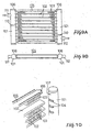
10 is generally known. The heat exchanger includes a pair of hollow
headers 101 and 101 arranged in parallel, a plurality of flat tubes
102 disposed in parallel between the headers 101 and 101 and
connected thereto and corrugated fins 103 each disposed between the
adjacent tubes 102. As shown in Fig. 10, each tube 102 is connected
to the headers 101 such that both end portions of the tube 102 are
brazed to the headers 101 in a state that the end potions are inserted
into the circumferentially extending slit-shaped tube fitting
aperture 104 formed in the opposed surfaces of the headers 101.
Furthermore a corrugated fin 103 is disposed at the outside
surface of the outermost tube 102 in order to improve the heat
exchange efficiency, and a side plate 105 is disposed at the outside
surface of the corrugated fin 103 for the purpose of protecting the
fin 103 and the like. As shown in Fig. 10, at both ends of this
side plate 105, an outwardly protruded fitting portion 106 having
a small width is formed respectively. This side plate 105 is
integrally brazed to the headers 101 in a state that the fitting
portion 106 is fitted in the side plate fitting aperture 107 having
a narrow width formed in the opposed surfaces of the headers 101
and 101. The reference numeral 110 denotes a partitioning plate,
111 denotes an inlet pipe and 112 denotes an outlet pipe.
According to the heat exchanger having the aforementioned
conventional structure, it is required to provide the protruded
fitting portions 106 at both ends of the side plate 105. However,
it is technically difficult to form such a protruded fitting portion
106 by end processing, resulting in deteriorated productivity and
an increased cost.
Furthermore, it is required to form two different types of
apertures in the external surface of each header 101, i.e., side
plate fitting apertures 107 for receiving the protruded fitting
portion 106 and the tube fitting apertures 104 for receiving the
tube 102. In other words, it is required to use different tools
for forming the side plate fitting apertures 107 and the tube fitting
apertures 104, which results in deteriorated productivity and an
increased cost.
The present invention is made in view of the aforementioned
technical background and aims to provide a heat exchanger which is
excellent in productivity and capable of decreasing the
manufacturing cost by eliminating the necessity of forming a special
fitting configuration at end portions of a side plate and enhancing
the workability for forming side plate fitting apertures and tube
fitting apertures.
Disclosure of Invention
The aforementioned object can be attained by a heat exchanger
including a hollow header having a plurality of tube fitting
apertures arranged in line, a plurality of tubes communicated with
the header, each tube having one end fitted in a corresponding tube
fitting aperture, a fin disposed at an outside of an outermost tube,
and a side plate disposed at an outside of the fin, wherein the header
is further provided with a side plate fitting aperture having the
same or approximately the same configuration as that of the tube
fitting aperture, wherein a header insertion end portion of the side
plate is formed into a cross-sectional peripheral configuration
corresponding to a cross-sectional peripheral configuration of the
side plate fitting aperture, and wherein the header insertion end
portion of the side plate is fitted in the side plate fitting aperture
and secured thereto.
Furthermore, the aforementioned object can also be attained
by a heat exchanger includes a pair of hollow headers arranged in
parallel, a plurality of tubes disposed in parallel between the
headers and communicated with the headers with opposite end portions
fitted in tube fitting apertures formed in opposed surfaces of the
pair of headers, fins disposed between adjacent tubes and at an
outside of an outermost tube, and a side plate disposed at an outside
of an outermost fin with opposite end portions fitted in side plate
fitting apertures formed in opposed surfaces of the pair of headers,
wherein a header insertion end portion constituting one of both end
portions of the side plate is formed into the same or approximately
the same cross-sectional peripheral configuration as that of an end
portion of the tube, and wherein the side plate fitting aperture
is formed into the same or approximately the same configuration as
that of the tube fitting aperture.
In the heat exchanger according to the present invention,
since the side plate fitting aperture and the tube fitting aperture
formed in the headers have the same or approximately the same
configuration, the aperture forming operations can be completed by
forming a plurality of the same or approximately the same apertures
in the header, and therefore it is not required to form a conventional
side plate fitting apertures different from the tube fitting
apertures. This enhances the workability of forming fitting
apertures in the header, which in turn reduces the manufacturing
cost. Furthermore, since the end portion of the side plate is formed
into the same or approximately the same cross-sectional peripheral
configuration as that of an end portion of the tube, it is not
required to perform specific end portion processing to an end
portion of the side plate for forming a protruded fitting portion
which is technically difficult. Accordingly, the quality of
product can be improved and the cost can be decreased because of
the enhanced workability.
As the fin, it is preferable to use a corrugated fin
constituted by an aluminum brazing sheet comprising a core member
and brazing materials coated on one side or both sides of the core
member.
It is preferable that the side plate is provided with a header
inserting portion having a contacting piece vertically extending
relative to the side plate, and wherein the side plate is secured
to the header with a header fitting surface of the contacting piece
fitted to an external surface of the header. In this case, since
the joining area increases when the header fitting surface of the
contacting piece is secured to the external surface of the header,
the joining strength increases notably. Furthermore, the
existence of the contacting piece effectively prevents the
contraction in the right-and-left direction (the longitudinal
direction of the side plate) at the time of joining such as brazing.
It is preferable that the contacting piece is extended toward
an inside of the side plate. In this case, it becomes unnecessary
to newly provide a contacting piece fitting space at the tip end
position of the external surface of the header (at the position
located outside the side plate), resulting in a shortened header
length, which in turn can meet the demand of compactness of a heat
exchanger.
It is preferable that the contacting piece is formed by
bending a cut-part of a widthwise edge portion of the header
inserting end portion. In this case, there is a merit that the
productivity can be improved regardless of the existence of the
contacting piece.
It is preferable that the header inserting end portion of the
side plate is formed into a tapered shape having a width decreasing
toward a tip thereof. By forming the header inserting end portion
into such a tapered shape, the insertion of the end portion of the
side plate into the side plate fitting aperture can be performed
smoothly, and the side plate can be fitted into the headers in a
positioned state.
Alternatively, the header inserting end portion of the side
plate may have a first tapered portion as an insertion guide at a
tip end thereof and a second tapered portion for an insertion amount
restricting portion at an inside position of the header inserting
end portion. In this case, there are merits that it becomes easy
to insert the side plate into the header and the assembly work can
be done easily because of the regulated header insertion amount.
The side plate may have a width which is the same or
approximately the same as a width of the tube and a thickness which
is the same or approximately the same as a height of the tube.
The aforementioned heat exchanger can be preferably used for
a condenser in a refrigeration cycle in which a refrigerant
compressed by a compressor is condensed by a condenser, the
condensed refrigerant is decompressed by passing through a
decompressing device, and the decompressed refrigerant is
evaporated by an evaporator and then returned to the compressor.
Brief Description of Drawings
The aforementioned objects and another objects as well as
features and advantages will be more apparent from the following
detailed description of the present invention with reference to the
attached drawings: in which
Best Mode for Carrying Out the Invention
A heat exchanger according to an embodiment of the present
invention is shown in Figs. 1 to 6. This heat exchanger is used
as a condenser for car air-conditioners, and the reference numeral
1 denotes a hollow header, 3 denotes a tube, 4 denotes a corrugated
fin, 5 denotes a side plate, 6 denotes a tube fitting aperture and
7 denotes a side plate fitting aperture.
Each of the pair of hollow headers 1 and 1 disposed in parallel
is manufactured by forming an aluminum brazing sheet including a
core member and brazing layers coated on both sides of the core member
into a cylindrical shape with opposite side end portions abutted
against each other and brazing the side end portions. The header
is a hollow tube having a round cross-section. The header may be
the so-called electric resistance welded pipe formed by joining the
side edge portions by electric resistance welding, or may be a
cylindrical aluminum extruded formed member with no side edge
portions abutted against each other.
A partitioning plate 15 is disposed in the header 1, whereby
the inner space of the header 1 is divided into a plurality of
chambers arranged in the longitudinal direction of the header.
In each peripheral wall of the opposed sides of the headers
1 and 1, as shown in Fig. 3, tube fitting apertures 6 are provided
at certain intervals along the longitudinal direction of the header.
Both ends of the tube 3 disposed in parallel between the headers
1 are inserted into the tube fitting apertures 6 and brazed thereto,
whereby the tube 3 and the header 1 are communicated with each other.
The tube 3 is constituted by a multi-bored flat aluminum
extruded member. In place of the extruded tube, the tube 3 may be
the so-called electric resistance welded pipe.
Between the adjacent tubes 3 and at the outside of the
outermost tube 3, a corrugated fin 4 is disposed respectively. This
corrugated fin 4 is constituted by an aluminum brazing sheet
including a core member and brazing layers coated on one side or
both sides of the core member.
Furthermore, at the outside of the outermost side corrugated
fin 4, the side plate 5 is disposed. Each end portion 5a of this
side plate 5 is inserted into a circumferentially extending
slit-shaped side plate fitting aperture 7 formed at both end
portions of the opposed surfaces of the headers 1 and 1, and brazed
thereto.
As shown in Fig. 3, the side plate fitting aperture 7 is formed
to have the same configuration as that of the tube fitting aperture
6. Accordingly, forming fitting apertures in the header 1 can be
done by forming a plurality of apertures each having the same
configuration. As a result, it becomes unnecessary to form an
aperture having a configuration different from that of the tube
fitting aperture, resulting in enhanced workability of forming
apertures in the header 1, which in turn can reduce the manufacturing
cost.
Furthermore, as shown in Fig. 2, the cross-sectional
peripheral configuration of the end portion 5a of the side plate
5 is formed into a cross-sectional peripheral configuration
identical to that of the end portion of the tube 3. As a result,
it becomes unnecessary to perform special end processing for forming
a fitting protrusion which is technically difficult to an end
portion of the tube 3, resulting in enhanced product quality and
workability, which in turn can reduce the manufacturing cost.
The end portion 5a of the side plate 5 may be formed to have
a cross-sectional peripheral configuration which is approximately
the same cross-sectional peripheral configuration of the end
portion of the tube 3. For example, the end portion 5a of the side
plate 5 and the end portion of the tube 3 may be formed into a
cross-sectional peripheral configuration as shown in Fig. 7.
Namely, the width of the side plate 5 may be the same or approximately
the same width of the tube 3, and the thickness of the side plate
5 may be the same or approximately the same height of the tube 3.
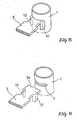
At both end portions 5a of the side plate 5, contacting pieces
10 extended inwardly and vertically relative to the side plate 5
are provided (see Figs. 1 and 6). As shown in Fig. 5, since these
contacting pieces 10 are brazed to the header 1 with the fitting
surfaces 10a of the contacting pieces fitted to the external
surfaces of the header 1, the joining area of the header 1 and the
side plate 5 increases, resulting in remarkably increased joining
strength thererbetween. Accordingly, a heat exchanger excellent
in durability can be provided. Furthermore, since such contacting
pieces 10 are protruded, the generation of contraction in the
right-and-left direction of the heat exchanger (in the
longitudinal direction of the side plate) at the time of brazing,
etc., can be effectively prevented.
In addition, since the contacting piece 10 is formed by
bending the cut-portion of the part of the widthwise edge portion
of the side plate 5, the productivity is excellent in spite of
employing additional protruded members.
Furthermore, as shown in Fig. 4, the end portion 5a of the
side plate 5 is formed into a tapered shape having a width which
decreases toward the tip end. Accordingly, the insertion of the
end portion into the side plate fitting aperture 7 can be performed
smoothly, and a proper positioning to the header can be attained.
As a tapered configuration of the end portion 5a of the side
plate 5, as shown in Fig. 8, two stepped tapered configuration may
be employed. That is, it may be constituted that the tip end portion
5a of the side plate 5 is formed into a tapered shape constituting
a first tapered portion 20 and an inner portion of the tip end portion
5a is formed into a tapered shape constituting a second tapered
portion 21. In the embodiment shown in Fig. 8, the inclination angle
of the second tapered portion 21 is set to 10° relative to the axial
direction of the side plate 5 (inclined by 10° relative to the axial
direction).
In the aforementioned embodiment, although the structure in
which the contacting pieces 10 are provided at the end portion 5a
of the side plate 5 is adopted, the structure in which such contacting
pieces are not provided may be adopt.
Now, in general, the heat exchanger according to the present
invention is manufactured by provisionally assembling each
component 1, 3, 4 and 5, and integrally secured by furnace brazing,
etc.
As mentioned above, in the heat exchanger according to the
present invention, since the side plate fitting aperture 7 and the
tube fitting aperture 6 formed in the headers 1 have the same or
approximately the same configuration, the aperture forming
operations can be performed by forming a plurality of the same or
approximately the same apertures in the header 1, and therefore it
becomes unnecessary to form conventional side plate fitting
apertures different from the tube fitting apertures. This enhances
the workability of forming fitting apertures in the header 1, which
in turn reduces the manufacturing cost.
Furthermore, since the end portion of the side plate 5 is
formed into the same or approximately the same cross-sectional
peripheral configuration as that of an end portion of the tube 3,
it is not required to perform specific end portion processing to
an end portion of the side plate 5 for forming a protruded fitting
portion which is technically difficult. Accordingly, the quality
of product can be improved and the cost can be reduced because of
an enhanced workability.
In cases where a corrugated fin constituted by an aluminum
brazing sheet comprising a core member and brazing materials coated
on one side or both sides of the core member is used as a fin, the
joining of the fins and the tubes can be collectively performed in
a furnace.
In cases where the side plate is provided with a header
inserting portion having a contacting piece vertically extending
relative to the side plate and the side plate is secured to the header
with a header fitting surface of the contacting piece fitted to an
external surface of the header, since the joining area increases
when the header fitting surface of the contacting piece is secured
to the external surface of the header, the joining strength
increases notably. Furthermore, the existence of the contacting
piece effectively prevents the contraction in the right-and-left
direction (the longitudinal direction of the side plate) at the time
of joining such as brazing.
In cases where the contacting piece is extended toward an
inside of the side plate, since the header length can be shortened,
the compactness of heat exchanger can be attained.
In cases where the contacting piece is formed by bending a
cut-part of a widthwise edge portion of the header inserting end
portion, the productivity can be improved regardless of the
existence of the contacting piece.
In cases where the header inserting end portion of the side
plate is formed into a tapered shape having a width decreasing toward
a tip thereof, the insertion of the end portion of the side plate
into the side plate fitting aperture can be performed smoothly, and
the side plate can be secured to the headers in a positioned state.
In cases where the header inserting end portion of the side
plate has a first tapered portion as an insertion guide at a tip
end thereof and a second tapered portion for an insertion amount
restricting portion at an inside position of the header inserting
end portion, it becomes easy to insert the side plate into the header
and the assembly work can be done easily because of the regulated
header insertion amount.
In cases where the side plate has a width which is the same
or approximately the same as a width of the tube and a thickness
which is the same or approximately the same as a height of the tube,
the freedom of design can be enhanced because it is only required
to design such that the width and the height of the side plate is
the same or approximately the same as those of the tube.
The terms and descriptions in this specification are used only
for explanatory purposes and the present invention is not limited
to these terms and descriptions. The present invention permits any
design-change, unless it deviates from the soul, if it is within
the limits by which the claim was performed.
Industrial Applicability
The present invention is preferably used for a metal heat
exchanger such as the so-called multi-flow type aluminum heat
exchanger used for a car air-conditioning condenser and the like.