EP1419844A1 - Electrical shield for a welding apparatus - Google Patents
Electrical shield for a welding apparatus Download PDFInfo
- Publication number
- EP1419844A1 EP1419844A1 EP03024422A EP03024422A EP1419844A1 EP 1419844 A1 EP1419844 A1 EP 1419844A1 EP 03024422 A EP03024422 A EP 03024422A EP 03024422 A EP03024422 A EP 03024422A EP 1419844 A1 EP1419844 A1 EP 1419844A1
- Authority
- EP
- European Patent Office
- Prior art keywords
- electrical
- shield
- welding apparatus
- stud
- planar side
- Prior art date
- Legal status (The legal status is an assumption and is not a legal conclusion. Google has not performed a legal analysis and makes no representation as to the accuracy of the status listed.)
- Granted
Links
- 238000003466 welding Methods 0.000 title claims abstract description 81
- 229910052751 metal Inorganic materials 0.000 claims abstract description 19
- 239000002184 metal Substances 0.000 claims abstract description 19
- 239000004033 plastic Substances 0.000 claims abstract description 12
- 239000000463 material Substances 0.000 claims description 9
- 238000000034 method Methods 0.000 claims description 7
- 229920002799 BoPET Polymers 0.000 claims description 5
- 239000005041 Mylar™ Substances 0.000 claims description 5
- 238000010276 construction Methods 0.000 claims description 5
- 239000002991 molded plastic Substances 0.000 claims description 5
- 239000012811 non-conductive material Substances 0.000 claims description 4
- 230000001681 protective effect Effects 0.000 abstract 1
- 238000005520 cutting process Methods 0.000 description 3
- 238000010438 heat treatment Methods 0.000 description 3
- WFKWXMTUELFFGS-UHFFFAOYSA-N tungsten Chemical compound [W] WFKWXMTUELFFGS-UHFFFAOYSA-N 0.000 description 3
- 229910052721 tungsten Inorganic materials 0.000 description 3
- 239000010937 tungsten Substances 0.000 description 3
- 229910052782 aluminium Inorganic materials 0.000 description 2
- XAGFODPZIPBFFR-UHFFFAOYSA-N aluminium Chemical compound [Al] XAGFODPZIPBFFR-UHFFFAOYSA-N 0.000 description 2
- 230000006698 induction Effects 0.000 description 2
- 239000012080 ambient air Substances 0.000 description 1
- 239000004020 conductor Substances 0.000 description 1
- 230000000977 initiatory effect Effects 0.000 description 1
- 239000007769 metal material Substances 0.000 description 1
- 238000012986 modification Methods 0.000 description 1
- 230000004048 modification Effects 0.000 description 1
- 238000000465 moulding Methods 0.000 description 1
- 230000002093 peripheral effect Effects 0.000 description 1
- 230000002250 progressing effect Effects 0.000 description 1
- 230000000153 supplemental effect Effects 0.000 description 1
- 238000005493 welding type Methods 0.000 description 1
Images



Classifications
-
- B—PERFORMING OPERATIONS; TRANSPORTING
- B23—MACHINE TOOLS; METAL-WORKING NOT OTHERWISE PROVIDED FOR
- B23K—SOLDERING OR UNSOLDERING; WELDING; CLADDING OR PLATING BY SOLDERING OR WELDING; CUTTING BY APPLYING HEAT LOCALLY, e.g. FLAME CUTTING; WORKING BY LASER BEAM
- B23K9/00—Arc welding or cutting
- B23K9/32—Accessories
Definitions
- the present invention relates generally to a welding apparatus and, more particularly, a portable welder having an electrical shield to prevent electrical arcing within the apparatus.
- Portable welding units transportable to a work site are known.
- Typical of such known units include a lightweight enclosure consisting of a sheet metal material, such as aluminum or other metal and which metal enclosure has a front panel and a rear panel at the ends of the enclosure to contain the various components of the welder therein and also includes a base that underlies the enclosure.
- portable welding units or apparatus are, by nature, small, compact units that can be readily carried by and individual and may easily weigh less than 15 pounds. In the construction of such portable welders, therefore, it is necessary to install a large number of components, including the various electrical components, in a relatively small space in order to provide a fully functional welder having the features desired by the user while still constructing the unit to be compact and lightweight.
- the voltage at the welding electrode and which is connected into a negative electrical receptacle externally provided in the welding apparatus can reach 12,000 volts and therefore the internal stud that is located internal of the welding apparatus and which is connected to the exterior electrical receptacle also experiences that high voltage.
- the internal stud that is located internal of the welding apparatus and which is connected to the exterior electrical receptacle also experiences that high voltage.
- there is a potential high voltage site that is, at the negative stud within that welding apparatus and, due to the extremely close quarters of the portable welding apparatus, the presence of the high voltage source can cause an arcing problem to occur within the apparatus itself.
- One of the more susceptible paths for that arcing is from the internal negative stud to the metal enclosure itself that surrounds the components of the welding apparatus; however, the problem obviously exists with respect to other electrically conductive components within the apparatus.
- the present invention is directed to an improved electrical shielding means to protect against electrical arcing within a portable welding apparatus.
- the welding apparatus itself is a portable apparatus comprised of a metal enclosure that houses the various components that are utilized in providing a variable power supply to carry out the welding process.
- the enclosure has a pair of end panels, that is, there is a front panel and a rear panel which are affixed to the enclosure to contain those components therein.
- the front and rear plastic panels are preferable constructed of a molded plastic material.
- a pair of electrical terminals In the front panel, there is provided a pair of electrical terminals. One of the terminals is a positive pole of an electric supply and the other electrical terminal is a negative pole of an electrical supply.
- Each of the electrical terminals comprises a female receptacle located on the external surface of the front panel and an electrical connector on the internal surface of the front panel.
- the internal connection is made by means of an electrical stud and which is connected to a bus bar internal of the apparatus to supply the electrical energy to that negative terminal.
- the female receptacles are adapted to be connected to cables that supply power to the welding electrode and to the workpiece.
- TIG welding the negative terminal is connected to a tungsten welding electrode and the positive terminal is connected to the workpiece.
- an electrical shield is provided that at least partially surrounds the negative electrical stud and which prevents arcs from being established from the high voltage at the negative electrical stud to the metal enclosure itself as well as to other electrically conductive components within the portable electrical apparatus.
- an electrical shield preferably formed of a non-conductive plastic material, and more preferably a plastic material commonly sold under the trademark MYLAR.
- the shield is formed of a plurality of planar sides that are pre-formed into the desired configuration and that configuration is a generally inverted U-shape that can be fitted into a plurality of ribs that can be molded into the end panel and which project outwardly from the inside surface of the end panel.
- the shield itself is preferably a one piece shield, pre-configured construction, having a large external side that is located between the electrical stud and the metal enclosure to protect against arcs between the electrical stud and that enclosure. There is also an upper planar side that extends over the top of the electrical stud, an internal planar side that is located inwardly of the electrical stud to complete the inverted U-shaped shield and there is a further lower planar side that extends inwardly from the lower edge of the internal planar side that extends inwardly toward the internal space of the enclosure.
- the overall shield surrounds the electrical stud on at least three sides and protects the electrical stud from arcing to the metal enclosure as well as other electrical and conductive components within the portable welding apparatus.
- Fig. 1 is a perspective view of a welding apparatus for which the present invention is applicable;
- Fig. 2 is a perspective view of the inside of the front panel of the welding apparatus of Fig. 1 showing the electrical shield of the present invention
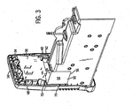
- Fig. 3 is a perspective view, taken from the side of the welding apparatus, and showing the electrical shield of the present invention in its installed position;
- Fig. 4 is an enlarged perspective view of the electrical shield of the present invention.
- the welding apparatus 10 comprises an enclosure 12 that is a sheet metal construction, preferable of aluminum, and having a front panel 14 and a rear panel 16. Both the front and rear panels 14, 16 are preferably constructed of a molded plastic material.
- the front panel 14 has a central control section and which includes the various controls for the welding functions and can include female receptacles 18, 20 that are used to connect the welding cables.
- female receptacle 18 is the positive source of electrical energy and the female receptacle 20 provides a negative source of the electrical energy.
- a control knob 22 is provided in order to control the current to the welding electrodes and a selector button 24 is provided to enable the welding apparatus 10 to be switched between TIG and stick operation. There may also be a series of LEDs 26 to provide an indication of status of the welding apparatus and to provide information as to its operation.
- a remote connector plug 28 is also used for the operation of a remote control such as a foot operated switch for the welding apparatus 10.
- a base 30 is located underneath the enclosure 12 and can also be a molded plastic construction and, as can be seen, the base 30 can be actually elevated with respect to the floor such that the welding apparatus 10 contacts the floor through the front and rear panels 14, 16.
- Fig. 1 shows the external surface 32 of the front panel 14, that is, the surface that faces outwardly of the internal space that is enclosed by the enclosure 12 and the front and rear panels 14, 16 to contain the various components used in the functioning of the welding apparatus 10.
- Fig. 2 taken along with Fig. 1, there is shown a perspective view of the front panel 14 and illustrating the internal surface 34 thereof.
- the front panel 14 includes a plurality of louvers 36 that allow the ambient air to circulate, by means of a fan (not shown) through the welding apparatus 10 in order to cool the various components contained in the internal space within the enclosure 12.
- a similar set of louvers is formed in the rear panel 14.
- circuitboard 38 for carrying out certain of the electrical functions of the overall welding apparatus 10 and, in the preferred embodiment, that circuitboard 38 is located in the upper area of the front panel 14 and affixed to the internal surface 34 thereof.
- the circuitboard 38 obviously includes a number of electrical components that are utilized and other conductive components.
- a positive electrical terminal 40 is provided to conduct the electric current through the front panel from a connector 42 at the internal surface 34 of the front panel 14 to the female receptacle 18 located at the external surface 32 of the front panel 14.
- the term electrical stud 46 is intended to mean any electrical connector, electrical contact or mounting hardware used in connection therewith.
- the arc starting system that is conventionally used on large welding apparatus can be used with the present portable welding apparatus 10 and therefore there will periodically be a high voltage in the range of about 12,000 volts at 60 hertz, present at the electrical stud 46 as well as with the various mounting. hardware or other components touching or abutting against and thus in conductive relationship with the electrical stud 46.
- an electrical shield 50 that is affixed to the Internal surface 34 of front panel 14 and which at least partially surrounds the electrical stud 46.
- the electrical shield 50 is preferable pre-configured into a desired shape and, in the preferred embodiment, that shape is an inverted U-shape.
- the electrical shield 50 is constructed of a non-conductive material, preferably a plastic material and, more preferable, a plastic material available under the trademark MYLAR and preferably has a thickness of about 10 to 15 thousandths of an inch.
- the inverted U-shape configuration is comprised of an external planar side 52 having an upper external edge 54 and a lower edge 56. As can be seen, the lower edge 56 extends a considerable distance below the electrical stud 46 in order to prevent the possible arc from passing around the lower edge 56 of the external planar side 52 from the electrical stud 46 to reach the metal enclosure 12.
- An upper planar side 58 extends inwardly toward the internal space of the enclosure 12 to an upper internal edge 60 and the upper planar side 58 is preferably approximately in a plane a right angle to the plane of the external planar side 52 and extends inwardly to the upper internal edge 60.
- Extending downwardly from the upper internal edge 60 is an internal planar side 62 and which is preferably in a plane approximately at a right angle to the plane of the upper planar side 58 and the Internal planar side 52 extends downwardly to a lower internal edge 64 that is located below the electrical stud 46.
- the external planar side 52, the upper planar side 58 and the internal planar side 62 form the Inverted generally U-shape of the electrical shield.
- a rib 70 that extends outwardly from the internal surface 34 of the front panel 14 and preferably the rib 70 is molded into the front panel 14 during the molding of the front panel 14 itself.
- the electrical shield 50 fits snugly against the rib 70 and the rib 70 helps to hold the electrical shield 50 in its position affixed to the internal surface 34.
- Fig, 3 there is shown a perspective view of the front panel 14 and showing the electrical shield 50 affixed thereto.
- further ribs 70 that affix the electrical shield 50 in position to the internal surface 34 of the front panel 14.
- the electrical shield 50 can be simply inserted into the proper position and held in that position by the plurality of ribs 70 to hold the electrical shield in that position.
- some supplemental means may be used to make sure the electrical shield 50 is sufficiently held in its desired position to the internal surface 34 of the front panel 14.
- Fig. 4 taken along with Figs. 1-3, there is shown a perspective view of the electrical shield 50 constructed in accordance with the present invention.
- the external planar side 52 is the longest side of the electrical shield 50 in view of its location intermediate the electrical stud 46 and the metal enclosure 12 when the welding apparatus 10 is assembled as in Fig. 1.
- the upper planar side 58 is, in the preferred embodiment, in a plane that is generally at a right angle with respect to the plane of the external planar side 52 and extends inwardly from the upper external edge 54 of that external planar side 52.
- the internal planar side 62 extends downwardly in a plane that is generally at a right angle with respect to the plane of the upper planar side 58.
- the inverted U-shape that is formed by the external planar side 52, the upper planar side 58 and the internal planar side 62 so that, as seen in Fig 2, the inverted U-shape at least partially surrounds the electrical stud 44.
- the space directly below the electrical stud 44 can be basically left with no shielding material since there are no conductive components in the near vicinity in the downward direction since only the plastic louvers 36 are in that area.
- the inward planar side 66 extends inwardly from the lower internal edge 64 of the internal planar side 62 to prevent arcs from passing around the lower internal edge 64 to reach the circuitboard 38.
- welding devices not only includes welders, but also includes any system that requires high power outputs, such as heating and cutting systems. Therefore, the present invention is equivalently applicable with any device requiring high power output, including welders, plasma cutters, induction heaters, and the like.
- Reference to welding power, welding-type power, or welders generally, includes welding, cutting or heating power.
- Description of a welding apparatus illustrates just one embodiment in which the present invention may be implemented. The present invention is equivalently applicable with many high power systems, such as cutting and induction heating systems, or any similar systems.
Landscapes
- Engineering & Computer Science (AREA)
- Physics & Mathematics (AREA)
- Plasma & Fusion (AREA)
- Mechanical Engineering (AREA)
- Arc Welding Control (AREA)
- Shielding Devices Or Components To Electric Or Magnetic Fields (AREA)
Abstract
Description
Claims (20)
- A portable welding apparatus comprising a metal enclosure and an end panel affixed to the metal enclosure forming an Internal space for containing electrically conductive components, the end panel having an electrical terminal with an external receptacle for receiving an external cable and an Internal electrical stud extending inwardly into the internal space, an electrical shield at least partially surrounding the Internal stud to prevent arcing between said Internal stud and an electrically conductive component or the metal enclosure.
- The welding apparatus as defined in claim 1 wherein the electrical shield is comprised of a thin non-conductive material.
- The welding apparatus as defined in claim 2 wherein the electrical shield is comprised of MYLAR plastic.
- The welding apparatus as defined in claim 1 wherein the end panel is a molded plastic construction and the end panel has a plurality of molded ribs extending inwardly into the internal space and wherein the electrical shield is fitted into the molded ribs.
- The welding apparatus as defined in claim 1 wherein the electrical shield has an external planar side having an upper edge and oriented in a vertical plane intermediate the Internal electrical stud and the metal enclosure.
- T he welding apparatus as defined in claim 5 wherein the electrical shield has an upper planar side extending inwardly from the upper edge of the external planar side into the internal space to form an inner edge displaced inwardly of the internal stud and the upper planar side is oriented in a horizontal plane located above the internal electrical stud.
- The welding apparatus as defined in claim 6 wherein the electrical shield has an internal planar side extending downwardly from the inner edge of the upper planar side and the inner planar side is oriented in a generally vertical plane and having a lower edge located below the internal electrical stud.
- The welding apparatus as defined in claim 7 wherein the electrical shield has a lower planar side extending inwardly toward the internal space from the lower edge of the internal planar side and the lower planar side has an inner edge displaced a predetermined distance inwardly therefrom.
- A shield for preventing arcing from a electrical stud of a portable welding apparatus, said shield comprising a generally inverted U-shaped configuration adapted to at least partially surround the electrical stud, said shield constructed of a non-conductive material, said inverted U-shaped shield having an first planar side having an upper edge, a second planar side extending inwardly from the upper edge of the first planar side and having an inner edge, said second planar side oriented in a plane generally perpendicular to the plane of the first planar side, a third planar side extending from the inner edge of the second planar side, said third planar side oriented in a plane generally parallel to the plane of the first planar side to form the inverted U-shape.
- The shield as defined in claim 9 where the non-conductive material is a plastic material and is preformed into the inverted U-shaped configuration.
- The shield as defined in claim 9 where the plastic material is MYLAR plastic and has a thickness of about 10-15 thousandths of an inch.
- A method of providing electrical shielding to prevent arcing in a portable welding apparatus, said method comprising the steps of:providing a portable welding apparatus comprising a conductive enclosure having an end panel, the end panel having an external surface and an internal surface to form an enclosed space with the conductive enclosure to contain conductive components, the end panel having an electrical terminal having a receptacle on the external surface and an electrical stud on the internal surface, the internal surface having a plurality of ribs extending outwardly therefrom,providing a pre-configured electrical shield, andaffixing the electrical shield to the internal surface of the end panel to at least partially surround the electrical stud by fitting the electrical shield into the ribs to shield the electrical stud against arcing to the conductive components or the conductive enclosure.
- The method of providing electrical shielding as defined in claim 12 wherein the step of providing a pre-configured electrical shield comprises providing a non-conductive electrical shield pre-configured in a generally U-shaped configuration.
- The method of providing electrical shielding as defined in claim 12 wherein the step of providing a portable welding apparatus comprises providing a portable welding apparatus having a molded plastic end panel and the plurality of ribs extending outwardly from the internal surface are molded into the end panel.
- A portable welding apparatus having a enclosure and at least one end panel joined to the enclosure to form an enclosed space for containing electrically conductive components, the end panel having a electrical stud affixed thereto and extending inwardly toward the enclosed space, a non-conductive shield comprising at least three planar sides, the non-conductive shield being affixed to the end panel to at least partially surrounding the electrical stud to prevent arcing between the electrical stud and an electrically conductive component.
- The portable welding apparatus of claim 15 wherein the at least three planar sides form a generally U-shaped configuration.
- The portable welding apparatus of claim 15 wherein the at least three planar sides are constructed of MYLAR plastic.
- The pprtable welding apparatus of claim 15 wherein the end panel has a plurality of ribs extending outwardly proximate the electrical stud and the non-conductive shield is affixed to the end panel by being interfitted within the ribs.
- The portable welding apparatus of claim 15 wherein one of the planar sides of the non-conductive shield is located intermediate the electrical stud and the enclosure.
- The portable welding apparatus of claim 15 wherein the portable welding apparatus has a circuitboard located within the enclosure and at least one of the planar sides of the non-conductive shield is located between the electrical stud and the circuitboard.
Applications Claiming Priority (2)
| Application Number | Priority Date | Filing Date | Title |
|---|---|---|---|
| US10/065,774 US6861586B2 (en) | 2002-11-18 | 2002-11-18 | Electrical shield for a welding apparatus |
| US65774 | 2002-11-18 |
Publications (2)
| Publication Number | Publication Date |
|---|---|
| EP1419844A1 true EP1419844A1 (en) | 2004-05-19 |
| EP1419844B1 EP1419844B1 (en) | 2008-12-10 |
Family
ID=32174098
Family Applications (1)
| Application Number | Title | Priority Date | Filing Date |
|---|---|---|---|
| EP03024422A Expired - Lifetime EP1419844B1 (en) | 2002-11-18 | 2003-10-23 | Electrical shield for a welding apparatus |
Country Status (3)
| Country | Link |
|---|---|
| US (2) | US6861586B2 (en) |
| EP (1) | EP1419844B1 (en) |
| DE (1) | DE60325161D1 (en) |
Cited By (1)
| Publication number | Priority date | Publication date | Assignee | Title |
|---|---|---|---|---|
| US20090188902A1 (en) * | 2008-01-29 | 2009-07-30 | Swartz John A | System and method for configuring a tig welding system using workpiece characteristics |
Families Citing this family (20)
| Publication number | Priority date | Publication date | Assignee | Title |
|---|---|---|---|---|
| USD520038S1 (en) * | 2004-01-02 | 2006-05-02 | Esab Ab | Welding machine |
| US8546728B2 (en) * | 2005-03-04 | 2013-10-01 | Illinois Tool Works Inc. | Welder with integrated wire feeder having single-knob control |
| US7411154B2 (en) * | 2005-03-24 | 2008-08-12 | Illinois Tool Works Inc. | Control panel for a welding-type apparatus |
| US8604389B2 (en) | 2006-02-06 | 2013-12-10 | Illinois Tool Works Inc. | Welding wire feed speed control system method |
| US9399263B2 (en) * | 2007-08-31 | 2016-07-26 | Hobart Brothers Company | Portable battery powered welder |
| US8569654B2 (en) | 2009-06-11 | 2013-10-29 | Illinois Tool Works Inc. | Systems and methods for wire feed speed control |
| CA2830995C (en) | 2011-03-25 | 2019-05-14 | Illinois Tool Works Inc. | Welding systems with means for adjust and displaying ranges of parameters for setting the latter; method of setting such welding parameters |
| AU339763S (en) * | 2011-11-15 | 2011-12-07 | Ensitech Ip Pty Ltd | Electrical Machinery Housing |
| USD679738S1 (en) * | 2012-03-21 | 2013-04-09 | Segala Bruno S.R.L. | Welding machine |
| US10369650B2 (en) | 2015-03-16 | 2019-08-06 | Illinois Tool Works Inc. | Welding parameter selection and notification systems and methods |
| US10773328B2 (en) | 2015-12-15 | 2020-09-15 | Illinois Tool Works Inc. | Welding system user interface having a color display for setting welding parameters |
| USD862545S1 (en) * | 2016-03-14 | 2019-10-08 | Zhejiang Lin Long Welding Equipment Co., Ltd. | Welding machine case |
| USD853457S1 (en) * | 2016-03-14 | 2019-07-09 | Zhejiang Lin Long Welding Equipment Co., Ltd. | Welding machine case |
| USD860276S1 (en) * | 2016-03-14 | 2019-09-17 | Zhejiang Lin Long Welding Equipment Co., Ltd. | Welding machine case |
| USD853458S1 (en) * | 2016-03-14 | 2019-07-09 | Zhejiang Lin Long Welding Equipment Co., Ltd. | Welding machine case |
| USD862544S1 (en) * | 2016-04-22 | 2019-10-08 | Zhejiang Lin Long Welding Equipment Co., Ltd. | Welding machine case |
| USD849809S1 (en) * | 2018-03-16 | 2019-05-28 | Lincoln Global, Inc. | Welder enclosure |
| USD844035S1 (en) * | 2018-03-16 | 2019-03-26 | Lincoln Global, Inc. | Welder enclosure |
| USD1074769S1 (en) * | 2022-08-31 | 2025-05-13 | Esab Ab | Power source housing element |
| USD1021986S1 (en) * | 2023-07-03 | 2024-04-09 | Shenzhen Jin Qing Innovation Technology Co., LTD | Welding machine |
Citations (6)
| Publication number | Priority date | Publication date | Assignee | Title |
|---|---|---|---|---|
| GB450800A (en) * | 1934-11-01 | 1936-07-24 | British Thomson Houston Co Ltd | Improvements in and relating to electric transformers |
| US3636637A (en) * | 1970-05-06 | 1972-01-25 | Graphic Pollution Control Inc | Method and apparatus for drying liquid deposited on liquid receptive material |
| US3749967A (en) * | 1971-12-23 | 1973-07-31 | Avco Corp | Electron beam discharge device |
| US5129843A (en) * | 1991-06-19 | 1992-07-14 | Emerson Electric Co. | Connector block for a terminal assembly |
| US5742000A (en) * | 1993-11-03 | 1998-04-21 | Carolina Power & Light Company | Device and method for preventing arcing and resultant flashing during repairs performed inside pad-mounted transformers |
| US6193548B1 (en) * | 1997-01-09 | 2001-02-27 | Illinois Tool Works Inc. | Connector for a power supply |
Family Cites Families (2)
| Publication number | Priority date | Publication date | Assignee | Title |
|---|---|---|---|---|
| US6225596B1 (en) * | 1996-03-20 | 2001-05-01 | Century Mfg. Co. | Portable welding unit |
| US6075226A (en) * | 1998-10-20 | 2000-06-13 | Kishbaugh; Daniel J. | Portable holding oven for welding electrodes utilizing exhaust heat from welding machine |
-
2002
- 2002-11-18 US US10/065,774 patent/US6861586B2/en not_active Expired - Lifetime
-
2003
- 2003-10-23 EP EP03024422A patent/EP1419844B1/en not_active Expired - Lifetime
- 2003-10-23 DE DE60325161T patent/DE60325161D1/en not_active Expired - Lifetime
-
2004
- 2004-03-29 US US10/811,520 patent/US20040178183A1/en not_active Abandoned
Patent Citations (6)
| Publication number | Priority date | Publication date | Assignee | Title |
|---|---|---|---|---|
| GB450800A (en) * | 1934-11-01 | 1936-07-24 | British Thomson Houston Co Ltd | Improvements in and relating to electric transformers |
| US3636637A (en) * | 1970-05-06 | 1972-01-25 | Graphic Pollution Control Inc | Method and apparatus for drying liquid deposited on liquid receptive material |
| US3749967A (en) * | 1971-12-23 | 1973-07-31 | Avco Corp | Electron beam discharge device |
| US5129843A (en) * | 1991-06-19 | 1992-07-14 | Emerson Electric Co. | Connector block for a terminal assembly |
| US5742000A (en) * | 1993-11-03 | 1998-04-21 | Carolina Power & Light Company | Device and method for preventing arcing and resultant flashing during repairs performed inside pad-mounted transformers |
| US6193548B1 (en) * | 1997-01-09 | 2001-02-27 | Illinois Tool Works Inc. | Connector for a power supply |
Cited By (3)
| Publication number | Priority date | Publication date | Assignee | Title |
|---|---|---|---|---|
| US20090188902A1 (en) * | 2008-01-29 | 2009-07-30 | Swartz John A | System and method for configuring a tig welding system using workpiece characteristics |
| WO2009097190A1 (en) * | 2008-01-29 | 2009-08-06 | Illinois Tool Works Inc. | System and method for configuring a tig welding system using workpiece characteristics |
| US9174295B2 (en) * | 2008-01-29 | 2015-11-03 | Illinois Tool Works, Inc. | System and method for configuring a TIG welding system using workpiece characteristics |
Also Published As
| Publication number | Publication date |
|---|---|
| US20040178183A1 (en) | 2004-09-16 |
| EP1419844B1 (en) | 2008-12-10 |
| DE60325161D1 (en) | 2009-01-22 |
| US6861586B2 (en) | 2005-03-01 |
| US20040095704A1 (en) | 2004-05-20 |
Similar Documents
| Publication | Publication Date | Title |
|---|---|---|
| US6861586B2 (en) | Electrical shield for a welding apparatus | |
| US9040869B2 (en) | Plasma cutter having microprocessor control | |
| CN103828489B (en) | Plasma spray gun with ergonomic gun handle | |
| CN111496349A (en) | Welding system and apparatus with configurable personal computer user interface | |
| US6815641B2 (en) | Handle for welding gun and system using same | |
| US20130081842A1 (en) | Non-welding device powered by a welding power supply | |
| JP3160347U (en) | Load testing equipment | |
| US7022935B1 (en) | Plasma-cutting torch with integrated high frequency starter | |
| CA2399539A1 (en) | A welding torch for use in gas metal arc welding | |
| JP2018125952A (en) | Power supply control device | |
| CN110214070B (en) | Hand-held power tool | |
| US20080116177A1 (en) | System for improved high frequency arc starting of a welding process | |
| CA2466787A1 (en) | Stud welder | |
| CA2831285C (en) | Plasma torch systems having improved plasma nozzles | |
| JP5319472B2 (en) | DC outlet | |
| US9486873B2 (en) | Fingertip and foot pedal amperage control combination apparatus and method | |
| JP7144857B2 (en) | Battery TIG Welder | |
| JPS57165178A (en) | Arc welding device | |
| US10335886B1 (en) | Vibrating welding system | |
| JP2015123540A (en) | Power tool | |
| JP5566479B2 (en) | Capacitor-circuit board interface for welding system components | |
| CA2350977A1 (en) | A device with a plasma torch | |
| JP3132166B2 (en) | Arc welding equipment | |
| US20120024823A1 (en) | Collet assembly with a universal collet | |
| KR20040018138A (en) | Power source device |
Legal Events
| Date | Code | Title | Description |
|---|---|---|---|
| PUAI | Public reference made under article 153(3) epc to a published international application that has entered the european phase |
Free format text: ORIGINAL CODE: 0009012 |
|
| AK | Designated contracting states |
Kind code of ref document: A1 Designated state(s): AT BE BG CH CY CZ DE DK EE ES FI FR GB GR HU IE IT LI LU MC NL PT RO SE SI SK TR |
|
| AX | Request for extension of the european patent |
Extension state: AL LT LV MK |
|
| 17P | Request for examination filed |
Effective date: 20040823 |
|
| AKX | Designation fees paid |
Designated state(s): DE FR IT |
|
| 17Q | First examination report despatched |
Effective date: 20060824 |
|
| GRAP | Despatch of communication of intention to grant a patent |
Free format text: ORIGINAL CODE: EPIDOSNIGR1 |
|
| GRAS | Grant fee paid |
Free format text: ORIGINAL CODE: EPIDOSNIGR3 |
|
| GRAA | (expected) grant |
Free format text: ORIGINAL CODE: 0009210 |
|
| AK | Designated contracting states |
Kind code of ref document: B1 Designated state(s): DE FR IT |
|
| REF | Corresponds to: |
Ref document number: 60325161 Country of ref document: DE Date of ref document: 20090122 Kind code of ref document: P |
|
| PLBE | No opposition filed within time limit |
Free format text: ORIGINAL CODE: 0009261 |
|
| STAA | Information on the status of an ep patent application or granted ep patent |
Free format text: STATUS: NO OPPOSITION FILED WITHIN TIME LIMIT |
|
| 26N | No opposition filed |
Effective date: 20090911 |
|
| PGFP | Annual fee paid to national office [announced via postgrant information from national office to epo] |
Ref country code: FR Payment date: 20121107 Year of fee payment: 10 Ref country code: DE Payment date: 20121029 Year of fee payment: 10 |
|
| PGFP | Annual fee paid to national office [announced via postgrant information from national office to epo] |
Ref country code: IT Payment date: 20121023 Year of fee payment: 10 |
|
| REG | Reference to a national code |
Ref country code: DE Ref legal event code: R119 Ref document number: 60325161 Country of ref document: DE Effective date: 20140501 |
|
| REG | Reference to a national code |
Ref country code: FR Ref legal event code: ST Effective date: 20140630 |
|
| PG25 | Lapsed in a contracting state [announced via postgrant information from national office to epo] |
Ref country code: DE Free format text: LAPSE BECAUSE OF NON-PAYMENT OF DUE FEES Effective date: 20140501 Ref country code: IT Free format text: LAPSE BECAUSE OF NON-PAYMENT OF DUE FEES Effective date: 20131023 Ref country code: FR Free format text: LAPSE BECAUSE OF NON-PAYMENT OF DUE FEES Effective date: 20131031 |