EP1419723B1 - AC/DC hand portable wet/dry vacuum having improved portability and convenience - Google Patents
AC/DC hand portable wet/dry vacuum having improved portability and convenience Download PDFInfo
- Publication number
- EP1419723B1 EP1419723B1 EP03025864A EP03025864A EP1419723B1 EP 1419723 B1 EP1419723 B1 EP 1419723B1 EP 03025864 A EP03025864 A EP 03025864A EP 03025864 A EP03025864 A EP 03025864A EP 1419723 B1 EP1419723 B1 EP 1419723B1
- Authority
- EP
- European Patent Office
- Prior art keywords
- battery
- power supply
- utility vacuum
- power
- assembly
- Prior art date
- Legal status (The legal status is an assumption and is not a legal conclusion. Google has not performed a legal analysis and makes no representation as to the accuracy of the status listed.)
- Expired - Lifetime
Links
- 239000007788 liquid Substances 0.000 claims abstract description 15
- 238000001816 cooling Methods 0.000 claims description 22
- 230000000903 blocking effect Effects 0.000 claims 1
- 239000000463 material Substances 0.000 description 17
- 230000008878 coupling Effects 0.000 description 9
- 238000010168 coupling process Methods 0.000 description 9
- 238000005859 coupling reaction Methods 0.000 description 9
- 239000000428 dust Substances 0.000 description 9
- 238000001914 filtration Methods 0.000 description 8
- 238000010276 construction Methods 0.000 description 6
- 238000004891 communication Methods 0.000 description 3
- 239000004744 fabric Substances 0.000 description 3
- 239000012530 fluid Substances 0.000 description 3
- 230000007246 mechanism Effects 0.000 description 3
- 230000008901 benefit Effects 0.000 description 2
- 238000007664 blowing Methods 0.000 description 2
- 229920001971 elastomer Polymers 0.000 description 2
- 239000013536 elastomeric material Substances 0.000 description 2
- 239000006260 foam Substances 0.000 description 2
- 238000003780 insertion Methods 0.000 description 2
- 230000037431 insertion Effects 0.000 description 2
- 230000035515 penetration Effects 0.000 description 2
- 239000004033 plastic Substances 0.000 description 2
- 238000011045 prefiltration Methods 0.000 description 2
- 238000009436 residential construction Methods 0.000 description 2
- 230000004044 response Effects 0.000 description 2
- 238000007789 sealing Methods 0.000 description 2
- 239000000872 buffer Substances 0.000 description 1
- 235000019504 cigarettes Nutrition 0.000 description 1
- 230000000694 effects Effects 0.000 description 1
- 239000000806 elastomer Substances 0.000 description 1
- 230000005611 electricity Effects 0.000 description 1
- 239000002657 fibrous material Substances 0.000 description 1
- 230000002209 hydrophobic effect Effects 0.000 description 1
- 230000008595 infiltration Effects 0.000 description 1
- 238000001764 infiltration Methods 0.000 description 1
- 239000012528 membrane Substances 0.000 description 1
- 238000005555 metalworking Methods 0.000 description 1
- 238000012986 modification Methods 0.000 description 1
- 230000004048 modification Effects 0.000 description 1
- 239000003921 oil Substances 0.000 description 1
- 239000002245 particle Substances 0.000 description 1
- 239000004810 polytetrafluoroethylene Substances 0.000 description 1
- 229920001343 polytetrafluoroethylene Polymers 0.000 description 1
- 239000012858 resilient material Substances 0.000 description 1
- 230000035939 shock Effects 0.000 description 1
- 230000003068 static effect Effects 0.000 description 1
- 230000001629 suppression Effects 0.000 description 1
- 238000012360 testing method Methods 0.000 description 1
- 238000012546 transfer Methods 0.000 description 1
- 238000011144 upstream manufacturing Methods 0.000 description 1
- 238000005406 washing Methods 0.000 description 1
- XLYOFNOQVPJJNP-UHFFFAOYSA-N water Substances O XLYOFNOQVPJJNP-UHFFFAOYSA-N 0.000 description 1
Images


Classifications
-
- A—HUMAN NECESSITIES
- A47—FURNITURE; DOMESTIC ARTICLES OR APPLIANCES; COFFEE MILLS; SPICE MILLS; SUCTION CLEANERS IN GENERAL
- A47L—DOMESTIC WASHING OR CLEANING; SUCTION CLEANERS IN GENERAL
- A47L9/00—Details or accessories of suction cleaners, e.g. mechanical means for controlling the suction or for effecting pulsating action; Storing devices specially adapted to suction cleaners or parts thereof; Carrying-vehicles specially adapted for suction cleaners
- A47L9/28—Installation of the electric equipment, e.g. adaptation or attachment to the suction cleaner; Controlling suction cleaners by electric means
- A47L9/2889—Safety or protection devices or systems, e.g. for prevention of motor over-heating or for protection of the user
-
- A—HUMAN NECESSITIES
- A47—FURNITURE; DOMESTIC ARTICLES OR APPLIANCES; COFFEE MILLS; SPICE MILLS; SUCTION CLEANERS IN GENERAL
- A47L—DOMESTIC WASHING OR CLEANING; SUCTION CLEANERS IN GENERAL
- A47L11/00—Machines for cleaning floors, carpets, furniture, walls, or wall coverings
- A47L11/40—Parts or details of machines not provided for in groups A47L11/02 - A47L11/38, or not restricted to one of these groups, e.g. handles, arrangements of switches, skirts, buffers, levers
- A47L11/4013—Contaminants collecting devices, i.e. hoppers, tanks or the like
- A47L11/4016—Contaminants collecting devices, i.e. hoppers, tanks or the like specially adapted for collecting fluids
- A47L11/4019—Fill level sensors; Security means to prevent overflow, e.g. float valves
-
- A—HUMAN NECESSITIES
- A47—FURNITURE; DOMESTIC ARTICLES OR APPLIANCES; COFFEE MILLS; SPICE MILLS; SUCTION CLEANERS IN GENERAL
- A47L—DOMESTIC WASHING OR CLEANING; SUCTION CLEANERS IN GENERAL
- A47L5/00—Structural features of suction cleaners
- A47L5/12—Structural features of suction cleaners with power-driven air-pumps or air-compressors, e.g. driven by motor vehicle engine vacuum
- A47L5/14—Structural features of suction cleaners with power-driven air-pumps or air-compressors, e.g. driven by motor vehicle engine vacuum cleaning by blowing-off, also combined with suction cleaning
-
- A—HUMAN NECESSITIES
- A47—FURNITURE; DOMESTIC ARTICLES OR APPLIANCES; COFFEE MILLS; SPICE MILLS; SUCTION CLEANERS IN GENERAL
- A47L—DOMESTIC WASHING OR CLEANING; SUCTION CLEANERS IN GENERAL
- A47L5/00—Structural features of suction cleaners
- A47L5/12—Structural features of suction cleaners with power-driven air-pumps or air-compressors, e.g. driven by motor vehicle engine vacuum
- A47L5/22—Structural features of suction cleaners with power-driven air-pumps or air-compressors, e.g. driven by motor vehicle engine vacuum with rotary fans
- A47L5/24—Hand-supported suction cleaners
-
- A—HUMAN NECESSITIES
- A47—FURNITURE; DOMESTIC ARTICLES OR APPLIANCES; COFFEE MILLS; SPICE MILLS; SUCTION CLEANERS IN GENERAL
- A47L—DOMESTIC WASHING OR CLEANING; SUCTION CLEANERS IN GENERAL
- A47L5/00—Structural features of suction cleaners
- A47L5/12—Structural features of suction cleaners with power-driven air-pumps or air-compressors, e.g. driven by motor vehicle engine vacuum
- A47L5/22—Structural features of suction cleaners with power-driven air-pumps or air-compressors, e.g. driven by motor vehicle engine vacuum with rotary fans
- A47L5/36—Suction cleaners with hose between nozzle and casing; Suction cleaners for fixing on staircases; Suction cleaners for carrying on the back
-
- A—HUMAN NECESSITIES
- A47—FURNITURE; DOMESTIC ARTICLES OR APPLIANCES; COFFEE MILLS; SPICE MILLS; SUCTION CLEANERS IN GENERAL
- A47L—DOMESTIC WASHING OR CLEANING; SUCTION CLEANERS IN GENERAL
- A47L7/00—Suction cleaners adapted for additional purposes; Tables with suction openings for cleaning purposes; Containers for cleaning articles by suction; Suction cleaners adapted to cleaning of brushes; Suction cleaners adapted to taking-up liquids
- A47L7/0004—Suction cleaners adapted to take up liquids, e.g. wet or dry vacuum cleaners
- A47L7/0023—Recovery tanks
- A47L7/0028—Security means, e.g. float valves or level switches for preventing overflow
-
- A—HUMAN NECESSITIES
- A47—FURNITURE; DOMESTIC ARTICLES OR APPLIANCES; COFFEE MILLS; SPICE MILLS; SUCTION CLEANERS IN GENERAL
- A47L—DOMESTIC WASHING OR CLEANING; SUCTION CLEANERS IN GENERAL
- A47L7/00—Suction cleaners adapted for additional purposes; Tables with suction openings for cleaning purposes; Containers for cleaning articles by suction; Suction cleaners adapted to cleaning of brushes; Suction cleaners adapted to taking-up liquids
- A47L7/0004—Suction cleaners adapted to take up liquids, e.g. wet or dry vacuum cleaners
- A47L7/0023—Recovery tanks
- A47L7/0038—Recovery tanks with means for emptying the tanks
-
- A—HUMAN NECESSITIES
- A47—FURNITURE; DOMESTIC ARTICLES OR APPLIANCES; COFFEE MILLS; SPICE MILLS; SUCTION CLEANERS IN GENERAL
- A47L—DOMESTIC WASHING OR CLEANING; SUCTION CLEANERS IN GENERAL
- A47L7/00—Suction cleaners adapted for additional purposes; Tables with suction openings for cleaning purposes; Containers for cleaning articles by suction; Suction cleaners adapted to cleaning of brushes; Suction cleaners adapted to taking-up liquids
- A47L7/0004—Suction cleaners adapted to take up liquids, e.g. wet or dry vacuum cleaners
- A47L7/0042—Gaskets; Sealing means
-
- A—HUMAN NECESSITIES
- A47—FURNITURE; DOMESTIC ARTICLES OR APPLIANCES; COFFEE MILLS; SPICE MILLS; SUCTION CLEANERS IN GENERAL
- A47L—DOMESTIC WASHING OR CLEANING; SUCTION CLEANERS IN GENERAL
- A47L9/00—Details or accessories of suction cleaners, e.g. mechanical means for controlling the suction or for effecting pulsating action; Storing devices specially adapted to suction cleaners or parts thereof; Carrying-vehicles specially adapted for suction cleaners
- A47L9/0009—Storing devices ; Supports, stands or holders
- A47L9/0018—Storing devices ; Supports, stands or holders integrated in or removably mounted upon the suction cleaner for storing parts of said suction cleaner
- A47L9/0027—Storing devices ; Supports, stands or holders integrated in or removably mounted upon the suction cleaner for storing parts of said suction cleaner specially adapted for holding the suction cleaning tools
-
- A—HUMAN NECESSITIES
- A47—FURNITURE; DOMESTIC ARTICLES OR APPLIANCES; COFFEE MILLS; SPICE MILLS; SUCTION CLEANERS IN GENERAL
- A47L—DOMESTIC WASHING OR CLEANING; SUCTION CLEANERS IN GENERAL
- A47L9/00—Details or accessories of suction cleaners, e.g. mechanical means for controlling the suction or for effecting pulsating action; Storing devices specially adapted to suction cleaners or parts thereof; Carrying-vehicles specially adapted for suction cleaners
- A47L9/0009—Storing devices ; Supports, stands or holders
- A47L9/0018—Storing devices ; Supports, stands or holders integrated in or removably mounted upon the suction cleaner for storing parts of said suction cleaner
- A47L9/0045—Storing devices ; Supports, stands or holders integrated in or removably mounted upon the suction cleaner for storing parts of said suction cleaner specially adapted for holding the suction tube
-
- A—HUMAN NECESSITIES
- A47—FURNITURE; DOMESTIC ARTICLES OR APPLIANCES; COFFEE MILLS; SPICE MILLS; SUCTION CLEANERS IN GENERAL
- A47L—DOMESTIC WASHING OR CLEANING; SUCTION CLEANERS IN GENERAL
- A47L9/00—Details or accessories of suction cleaners, e.g. mechanical means for controlling the suction or for effecting pulsating action; Storing devices specially adapted to suction cleaners or parts thereof; Carrying-vehicles specially adapted for suction cleaners
- A47L9/22—Mountings for motor fan assemblies
-
- A—HUMAN NECESSITIES
- A47—FURNITURE; DOMESTIC ARTICLES OR APPLIANCES; COFFEE MILLS; SPICE MILLS; SUCTION CLEANERS IN GENERAL
- A47L—DOMESTIC WASHING OR CLEANING; SUCTION CLEANERS IN GENERAL
- A47L9/00—Details or accessories of suction cleaners, e.g. mechanical means for controlling the suction or for effecting pulsating action; Storing devices specially adapted to suction cleaners or parts thereof; Carrying-vehicles specially adapted for suction cleaners
- A47L9/24—Hoses or pipes; Hose or pipe couplings
- A47L9/242—Hose or pipe couplings
-
- A—HUMAN NECESSITIES
- A47—FURNITURE; DOMESTIC ARTICLES OR APPLIANCES; COFFEE MILLS; SPICE MILLS; SUCTION CLEANERS IN GENERAL
- A47L—DOMESTIC WASHING OR CLEANING; SUCTION CLEANERS IN GENERAL
- A47L9/00—Details or accessories of suction cleaners, e.g. mechanical means for controlling the suction or for effecting pulsating action; Storing devices specially adapted to suction cleaners or parts thereof; Carrying-vehicles specially adapted for suction cleaners
- A47L9/26—Incorporation of winding devices for electric cables
-
- A—HUMAN NECESSITIES
- A47—FURNITURE; DOMESTIC ARTICLES OR APPLIANCES; COFFEE MILLS; SPICE MILLS; SUCTION CLEANERS IN GENERAL
- A47L—DOMESTIC WASHING OR CLEANING; SUCTION CLEANERS IN GENERAL
- A47L9/00—Details or accessories of suction cleaners, e.g. mechanical means for controlling the suction or for effecting pulsating action; Storing devices specially adapted to suction cleaners or parts thereof; Carrying-vehicles specially adapted for suction cleaners
- A47L9/28—Installation of the electric equipment, e.g. adaptation or attachment to the suction cleaner; Controlling suction cleaners by electric means
- A47L9/2868—Arrangements for power supply of vacuum cleaners or the accessories thereof
- A47L9/2878—Dual-powered vacuum cleaners, i.e. devices which can be operated with mains power supply or by batteries
-
- H—ELECTRICITY
- H02—GENERATION; CONVERSION OR DISTRIBUTION OF ELECTRIC POWER
- H02J—CIRCUIT ARRANGEMENTS OR SYSTEMS FOR SUPPLYING OR DISTRIBUTING ELECTRIC POWER; SYSTEMS FOR STORING ELECTRIC ENERGY
- H02J2207/00—Indexing scheme relating to details of circuit arrangements for charging or depolarising batteries or for supplying loads from batteries
- H02J2207/40—Indexing scheme relating to details of circuit arrangements for charging or depolarising batteries or for supplying loads from batteries adapted for charging from various sources, e.g. AC, DC or multivoltage
-
- Y—GENERAL TAGGING OF NEW TECHNOLOGICAL DEVELOPMENTS; GENERAL TAGGING OF CROSS-SECTIONAL TECHNOLOGIES SPANNING OVER SEVERAL SECTIONS OF THE IPC; TECHNICAL SUBJECTS COVERED BY FORMER USPC CROSS-REFERENCE ART COLLECTIONS [XRACs] AND DIGESTS
- Y10—TECHNICAL SUBJECTS COVERED BY FORMER USPC
- Y10S—TECHNICAL SUBJECTS COVERED BY FORMER USPC CROSS-REFERENCE ART COLLECTIONS [XRACs] AND DIGESTS
- Y10S15/00—Brushing, scrubbing, and general cleaning
- Y10S15/01—Rechargeable batter
Definitions
- the present invention generally relates to vacuum appliances and more particularly to an AC/DC powered hand-portable wet/dry vacuum having improved convenience and performance.
- wet/dry vacuums Vacuum appliances that are capable of picking up both wet and dry materials are commonly known as wet/dry vacuums. Such wet/dry vacuums are well known in the art and are commercially available in a variety of sizes and configurations. Recent consumer trends have placed significant cost pressures the commercially available wet/dry vacuums and as such, many manufacturers are presently producing low-end, relatively small capacity low-cost units and/or high-end, relatively high capacity high-cost professional grade units.
- the low-end, low-cost units are frequently employed by professional users, such as installers, service technicians and trades people in residential construction. These professionals are commonly required to clean their job site prior to leaving for their next job and as such, they frequently prefer the smaller size and portability that are typical of these units. These units, however, are known to have several drawbacks.
- One such drawback relates to convenience of the known wet/dry vacuums and in particular the relatively long amount of time that is necessary for their set-up, the frequency with which the hose becomes disconnected during transport or use and the frequency with which the attachments are lost. Due to the relative bulk of the known wet/dry vacuums and their attachments, the professional user frequently makes a dedicated trip to transport the wet/dry vacuum to or from a jobsite.
- Another drawback relates to the availability of electrical power on a given jobsite.
- new residential construction it is relatively common to encounter a jobsite where electrical power from an electrical utility is unavailable.
- a portable generator is required.
- the inconvenience of heavy extension cords and the expense and inconvenience of a portable generator is highly undesirable to a professional user, particularly considering that the professional user frequently uses the wet/dry vacuum for less than 10 minutes on a given jobsite.
- CH-A-575548 discloses a utility vacuum comprising a canister, a powerhead assembly coupled to the canister and comprising a fan with a fan inlet, a motor and a power supply controller for distributing electrical power to the motor.
- a shut-off device configured to prevent the fan from drawing a liquid into the fan inlet when the volume of the liquid in the canister exceeds a predetermined volume.
- an electrical power cord associated with the power supply controller and configured via a plug means to selectively couple the power supply controller to a source of alternating current power.
- a utility vacuum comprising the features of claim 1.
- a hand-portable wet/dry vacuum constructed in accordance with the teachings of the present invention is generally indicated by reference numeral 10.
- the vacuum 10 is shown to include a powerhead assembly 12, a canister assembly 14, a filter system 16, a hose assembly 18, a plurality of conventional hose-end attachments 20, a shoulder strap 22, a first electrical cord 24, a second electrical cord 26 and a battery pack 28.
- the powerhead assembly 12 may be removably attached to the canister assembly 14 and includes a housing 40, a motor 42, a fan 44 and a controller 46.
- the housing 40 defines an inlet port 50, an outlet port 52, a handle 54 and a central cavity 56 into which the motor 42, fan 44 and controller 46 are housed.
- the inlet port 50 may be routed to the canister assembly 14 on a first side of the filter system 16 while the outlet port 52 may be routed to the canister assembly 14 on a second side of the filter system 16. Air flowing into the inlet port 50 flows into the canister assembly 14 and through the filter system 16 prior to being directed out of the outlet port 52.
- the motor 42 and the fan 44 which is coupled for rotation with the output shaft (not shown) of the motor 42, cooperate to blow air out of the outlet port 52 to thereby draw air into the powerhead assembly 12 via the inlet port 50.
- the controller 46 is illustrated to preferably include a first electrical socket 60, a second electrical socket 62, a receptacle assembly 64, a power supply 66, a power switch 68 and a charger circuit 70.
- Each of the first and second electrical sockets 60 and 62 and the receptacle assembly 64 are electrically coupled to the power supply 66 and configured to conduct electrical power thereto as will be described in detail, below.
- the power supply 66 is electrically coupled to the motor 42 and the power switch 68 in a conventional manner to permit the user to selectively enable or disable the flow of electrical power to the motor 42.
- the first electrical cord 24 preferably includes a conventional pronged plug end 74, which is configured to be electrically coupled to a conventional electrical outlet 76, and a conventional first connector-end 78 that is configured electrically coupled to the first electrical socket 60. Accordingly, the first electrical cord 24 permits the user of the wet/dry vacuum 10 to couple the power supply 66 to a source of alternating current (AC) power.
- AC alternating current
- the second electrical cord 26 preferably includes a conventional cylindrical plug-end 84, which is configured to be electrically coupled to a conventional cigarette lighter socket 86 of an automotive vehicle, and a conventional second connector-end 88, which is configured to be electrically coupled to the second electrical socket 62. Accordingly, the second electrical cord 26 permits the user to couple the power supply 66 to a source of direct current (DC) power, such, as to the electrical system and battery of an automotive vehicle.
- DC direct current
- the receptacle assembly 64 is illustrated as being flexibly connected to the housing 40 via a flexible gasket 90.
- the gasket 90 is made of a flexible resilient material, such as rubber or another elastomer.
- the receptacle assembly 64 includes a receptacle housing 94, which is configured to receive the battery pack 28, and a connector 96 that is floatingly disposed in the receptacle housing 94 to minimize the shock received by a battery pack 28 if the wet/dry vacuum 10 is dropped.
- the connector 96 has a plurality of terminals (not shown) with a configuration that contacts the associated terminals (not shown) of the battery pack 28.
- the battery pack 28, terminals, - receptacle housing 94 and connector 96 are configured in the manner disclosed in U.S. Patent No. 5,144,217 .
- the receptacle assembly 64 permits the user to couple the power supply 66 to the battery pack 28 so that the wet/dry vacuum 10 may be operated without either of the first and second electrical cords 24 and 26 being coupled thereto, as when, for example, a source of AC or DC electrical power is unavailable or inconvenient to access.
- the power supply 66 is compatible with battery packs having various different voltages (e.g., 18v, 14v, 12v, and/or 9.6v) in a manner that is well known in the art.
- any manual or automatic means may be employed to select the source of power for the wet/dry vacuum 10.
- a conventional rotary switch may be provided to permit the user to manually select between AC power, DC power (from the second power cord 26) and a battery pack 28.
- an automatic switch (comprising transistors or any other suitable electrical device) may be employed such that the power supply 66 will "look" for one power type, such as AC power, first, and should it not be available, look for "DC" power from the second power cord 26 next and thereafter from the battery pack 28.
- the charger circuit 70 is coupled to the power supply 66 and the receptacle assembly 64 in a manner that is well known in the art.
- the charger circuit 70 allows for the charging of battery packs having different voltages, as is well known in the art.
- An example of a suitable charger circuit is disclosed in U.S.. - Patent No. 6,427,070 .
- a user can charge a battery pack 28, when the motor 42 is not running, by placing the battery pack 28 in the receptacle assembly 64 such that the terminals of the connector 96 electrically engage the associated terminals of the battery pack 28 and providing the wet/dry vacuum 10 with another source of electrical power via one of the first and second electrical cords 24 and 26.
- the battery pack 28 may then be removed from the receptacle assembly 64 and employed to power another device, such as the heavy-duty audio equipment of U.S. Patent No. 6,427,070 or the cordless drill/driver of U.S. Patent No. 6,431,289 .
- the canister assembly 14 preferably includes a canister 100 and a latching system 102 that releasably secures the canister 100 to the powerhead assembly 12.
- the particular canister illustrated has a capacity of about 7.57 litres (two gallons), but those skilled in the art will appreciate that the canister 100 may in the alternative have a capacity that is larger or smaller.
- the filter system 16 may be completely attached to the powerhead assembly 12 but in the particular example provided, is carried canister 100 and includes a plenum 110 that is releasably attachable to the powerhead assembly 12, a float ball 112, a primary filter 114 and a secondary filter 116.
- the plenum 110 may have a hollow, cage-like construction that permits air to flow therethrough.
- the plenum 110 serves to retain and support the primary filter 114 as well as retain and guide the float ball 112 in a generally vertical orientation.
- the float ball 112 rises automatically within the plenum 110 to close off the filter system 16 from the fan 44 (which cuts off the flow of air through the powerhead assembly 12) when liquid in the canister 100 reaches a predetermined level.
- the primary filter 114 may include a filter structure (not specifically shown), which is formed from a rigid plastic material, and a fabric filter material (not specifically shown) that completely surrounds at least side of the filter structure.
- the fabric filter material is preferably formed of a washable filter material so as to permit the primary filter 114 to be washed when loaded with dust or dirt, rather than disposed of and replaced.
- the primary filter 114 may be made of any suitable filtering material, including an open-cell foam or a conventional filter paper (in which case the primary filter 114 would be disposable).
- a pre-filter structure (not shown) may also be employed. Suitable pre-filter structures include wire mesh or plastic screens, or open-cell foam which serve to collect dust and dirt (e.g., drywall dust) before the dust-carrying airflow contacts the primary filter 114.
- the secondary filter 116 which is optional and in the particular example provided carried by the powerhead assembly 12, is disposed upstream of the primary filter 114 and is of a generally finer mesh or porosity so as to collect relatively small dust particles before they are expelled through the outlet port 52.
- the secondary filter 116 is preferably removable from the filter system 16 without disassembling the canister assembly from the powerhead assembly 12.
- an access port 130 is formed in the housing 40 between the primary filter 114 and the fan 44. When the secondary filter 116 is received into the access port 130, a gasketed door 132 that may be hingedly coupled to the housing 40 is closed to seal the access port 130 and ensure that air flowing to the fan 44 encounters the primary filter 114 and then the secondary filter 116.
- the purpose of the secondary filter 116 is to provide very fine filtering of the air passing through the wet/dry vacuum 10 so that dirt and dust are not expelled from the outlet port 52 when the wet/dry vacuum 10 is operated.
- the wet/dry vacuum 10 may also be used without the secondary filter 116 when the expelling of relatively fine dust from the outlet port 52 is not an issue.
- the hose assembly 18 is preferably a flexible vacuum hose which is fixedly coupled to the inlet port 50. Also preferably, the hose assembly 18 is at least partially retractable into the inlet port 50 so as to provide a convenient means for storage of the hose assembly 18. Alternatively, the hose assembly 18 may be removably friction fitted on a selective basis to the inlet port 50 (for vacuuming) or the outlet port 52 (for blowing).
- the distal end of the hose assembly 18 may be friction-fittable to any of the hose-end attachments 20.
- hose-end attachments 20 are well known in the art and as such, a detailed discussion of their construction and use need not be provided herein.
- a plurality of receiving slots 140 may be formed into the housing 40 and/or canister 100.
- the receiving slots 140 may be constructed to frictionally engage an associated one of the hose-end attachments 20.
- each hose-end attachment 20 may be coupled to the housing 40 and/or canister 100 via its associated receiving slot 140.
- the shoulder strap 22 which is optional, is coupled to the powerhead assembly 12 and permits the user of the wet/dry vacuum 10 to wear the unit over their shoulder so that their hands may be used for other tasks, including transporting other equipment or manipulating the hose assembly 18 when the wet/dry vacuum 10 is in use.
- the shoulder strap 22 is coupled to the handle 54, which is integrally formed with the housing 40.
- the hose assembly 18 is preferably fixedly coupled to the inlet port 50 and as such, is not connectable to the outlet port 52 so that the wet/dry vacuum 10 can be used as a blower in a conventional manner (i.e., by connecting the hose assembly 18 to the outlet port 52).
- the wet/dry vacuum 10 may include a valve assembly 150 that selectively controls the flow of air to the fan 44. More specifically, the valve assembly 150 may be a two-position four-way valve that includes an actuator 154 and a valve element 156. In the particular embodiment illustrated, the actuator 154 is a rotary style actuator that is movable between a first setting 160 and a second setting 162.
- the valve element 156 is coupled for rotation with the actuator 154 such that when the actuator 154 is positioned in the first setting 160, air is drawn from the inlet port 50 through the filter system 16 and into the fan 44 in the manner described above.
- the valve element 156 moves (e.g., rotates in the example provided) to cause the outlet port 52 to be in fluid communication with the inlet side of the filter system 16 and the inlet port 50 to be in fluid communication with the discharge side of the fan 44.
- various components of the wet/dry vacuum 10, such as the motor 42, the fan 44 and the primary filter 114, may be constructed and/or arranged in a manner that is well known in the art. Such components, constructions and arrangements are illustrated and discussed, for example, in U.S. Patent No. 6,363,574 .
- a second wet/dry vacuum constructed in accordance with the teachings of the present invention is generally indicated by reference numeral 10a.
- the wet/dry vacuum 10a is generally similar to the wet/dry vacuum 10 of Figure 1 except that the filter system .. 16a is integrated with the canister assembly 14a. More specifically, the plenum 110a is coupled to the canister 100a and the primary filter 114a completely shrouds the plenum 110a.
- a gasket 170 is compressed between the primary filter 114a and the powerhead assembly 12a to thereby sealingly engage the primary filter 114a to the powerhead assembly 12a.
- the primary filter 114a is removed from the canister 100a and the canister 100a may be overturned to empty its contents.
- the primary filter 114a is preferably at least partially constructed from a washable and re-usable filtering material to thereby eliminate the need for replacement filters. This configuration is advantageous in that all of the dirty components are located together and remain in an upright condition when they are being removed. In contrast to the known wet/dry vacuums wherein the filter system is coupled to the powerhead, dust and other debris remain contained within the canister 100a when the powerhead assembly 12a is removed. Furthermore, removal and/or replacement of the primary filter 114a is quick and efficient, as no fasteners are employed to fix the position of the primary filter 114a relative to the powerhead assembly 12a.
- FIG. 10b Another wet/dry vacuum constructed in accordance with the teachings of the present invention is generally indicated by reference numeral 10b.
- the wet/dry vacuum 10b is generally similar to the wet/dry vacuum 10a of Figure 7 except that the powerhead assembly 12b is pivotally (via a hinge 179, for example) attached to a housing 180 that houses the canister assembly 14b.
- the powerhead assembly 12b When the canister assembly 14b is to be removed from or inserted into the housing 180, the powerhead assembly 12b is pivoted upwardly as shown in Figure 9 . Once the canister assembly 14b is seated within the housing 180, the powerhead assembly 12b is pivoted downwardly so that a gasket 182 that is carried by the powerhead assembly 12b sealingly engages the canister 100b. Those skilled in the art will appreciate that the gasket 182 may alternatively be carried by the canister 100b. A conventional latch mechanism 183 may be employed to secure the powerhead assembly 12b to the canister assembly 14b.
- a fourth wet/dry vacuum constructed in accordance with the teachings of the present invention is generally indicated by reference numeral 10c.
- the wet/dry vacuum 10c is generally similar to the wet/dry vacuum 10b of Figures 8 and 9 except that the powerhead assembly 12c is fixedly attached to the housing 180c that houses the canister assembly 14c.
- the canister assembly 14c is therefore inserted to and removed from the housing 180c by sliding the canister assembly 14c into or out of the housing 180c.
- FIG. 10d yet another wet/dry vacuum constructed in accordance with the teachings of the present invention is generally indicated by reference numeral 10d.
- the wet/dry vacuum 10d is generally similar to the wet/dry vacuum 10c of Figures 10 and 11 , except that a secondary filter 116d is incorporated into the filter system 16d.
- the secondary filter 116d may be located between the fan 44 and the primary filter 114d and is relatively finer in porosity/mesh so that dirt and dust are not expelled from the outlet port 52 when the wet/dry vacuum 10d is operated.
- the secondary filter 116d may be removed and cleaned or replaced without removal of the canister assembly 14d.
- a sixth vacuum constructed in accordance with the teachings of the present invention is generally indicated by reference numeral 10e.
- the vacuum 10e is shown to preferably include a powerhead assembly 12e, a canister assembly 14e, a filter system 16e, a hose assembly 18e, a plurality of conventional hose-end attachments 20e, a shoulder strap 22e, an electrical cord 24e and a battery pack 28e.
- the powerhead assembly 12e may be removably attached to the canister assembly 14e and may include a housing 40e, a motor 42e, a fan 44e and a controller 46e.
- the housing 40e may define one or more of an inlet port 50e, an outlet port 52e, a handle 54e and a central cavity 56e into which the motor 42e, fan 44e and controller 46e may be housed.
- the inlet port 50e is routed into the canister assembly 14e on a first side of the filter system 16e while the outlet port 52e routes air out of the powerhead assembly 12e on a second side of the filter system 16e.
- Air flowing into the inlet port 50e may flow into the canister assembly 14e and through the filter system 16e prior to being directed out of the outlet port 52e.
- the motor 42e and the fan 44e which is coupled for rotation with the output shaft (not shown) of the motor 42e, cooperate to preferably blow air out of the outlet port 52e which thereby draws air into the canister assembly 14e via the inlet port 50e.
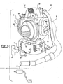
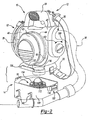
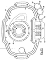
- the housing 40e may be configured to aid in the cooling of the motor 42e during its operation. More specifically, the housing 40e may be configured with one or more cooling inlet apertures 500 and one or more cooling outlet apertures 502, with both of the cooling inlet and outlet apertures 500 and 502 being in fluid communication with the central cavity 56e as will be described in greater detail, below. In the embodiment provided, a single cooling inlet aperture 500 and a single cooling outlet aperture 502 are employed. With additional reference to Figures 16 and 17 , the cooling inlet aperture 500 is illustrated as being concentrically disposed about the inlet port 50e to thereby disguise its location on the housing 40e, but those skilled in the art will appreciate that the cooling inlet aperture(s) 500 may be located at various other locations on the housing 40e.
- the cooling outlet aperture 502 may be located in the portion of the housing 40e that defines the outlet port 52e.
- the cooling outlet aperture 502 extends through a trailing portion 510 of a protrusion 512 that is formed on the wall 514 of the outlet port 52e and oriented in a direction such that a longitudinal axis of the protrusion 512 is generally parallel to the flow of air through the outlet port 52e.
- the particular vacuum 10e provided is configured such that during its operation, air flows through the outlet port 52e to create a zone 520 of relatively low static pressure proximate the cooling outlet aperture 502, causing air to flow from the central cavity 56e through the cooling outlet aperture 502 where it merges with the air flowing through the outlet port 52e.
- the air departing from the central cavity 56e likewise draws fresh air into the central cavity 56e through the cooling inlet aperture 500.
- the exchange of air in the central cavity 56e permits the motor 42e to reject relatively higher levels of heat. More specifically, the air flowing through the central cavity 56e provides an air stream permits that flows against the motor 42e to thereby permit the motor 42e to reject heat therefrom with a convective heat transfer mechanism.
- the controller 46e is illustrated to preferably include a receptacle assembly 64e, a power supply 66e, a power switch 68e and an optional charger circuit 70e.
- the receptacle assembly 64e is electrically coupled to the power supply 66e and configured to conduct electrical power thereto as will be described in detail, below.
- the power supply 66e is electrically coupled to the motor 42e and the power switch 68e to permit the user to selectively enable or disable the flow of electrical power to the motor 42e.
- the electrical cord 24e may include a conventional pronged plug end 74e, which is configured to be electrically coupled to a conventional electrical outlet 76e, and an opposite end (not shown) which is electrically coupled in a conventional manner to the power supply 66e. Accordingly, the electrical cord 24e may permit the user of the wet/dry vacuum 10e to couple the power supply 66e to a source of alternating current (AC) power.
- AC alternating current
- the receptacle assembly 64e may be generally similar to the receptacle assembly 64 of Figures 3 and 4 and as such, need not be discussed in significant detail.
- the receptacle assembly 64e is illustrated in Figure 19 to be disposed in a battery enclosure 550 that is coupled to or integrally formed with the housing 40e.
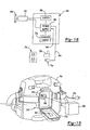
- a lid 552 may be hingedly coupled to the battery enclosure 550 and is movable between a closed position ( Figure 14 ), which substantially closes the battery enclosure 550, and an open position, which substantially clears the battery enclosure 550.
- An over-center camming latch mechanism 556 may be employed to selectively maintain the lid 552 in the closed position.
- An optional battery pack gasket 560 and leaf spring 562 may also be employed.
- the battery pack gasket 560 may be disposed between the battery pack 28e and one or both of the receptacle assembly 64e and the battery enclosure 550 (i.e., battery pack gaskets 560 in the latter example), while the leaf spring 562 may be attached to the lid 552 and positioned so as to push the battery pack 28e into electrical contact with the receptacle assembly 64e and sealing contact with the battery pack gasket 560 when the lid 552 is positioned in the closed position.
- the battery pack gasket 560 inhibits liquids from entering the receptacle assembly 64e and the interior of the housing 40e despite the presence of vent apertures 564 ( Figure 25 ) that extend through the battery enclosure 550 and/or lid 552.
- the receptacle assembly 64e permits the user to couple the power supply 66e to the battery pack 28e so that the wet/dry vacuum 10e may be operated when, for example, a source of AC electrical power is unavailable or inconvenient to access.
- the power supply 66e is compatible with battery packs having various different voltages (e.g., 18v, 14v, 12v, and/or 9.6v). Stated another way, the power supply 66e is preferably configured such that a first battery pack having a first output voltage and a second battery pack having a second output voltage that is different than the first output voltage may be used interchangeably to power the power supply 66e.
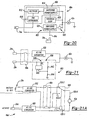
- the power supply 66e includes an AC/DC converter 600 and a DC/DC converter 602 as shown in Figure 20 .
- the AC/DC converter 600 preferably has an electromagnetic interference suppression module 610, a rectifier 612 for rectifying alternating current power input thereto from the electrical cord 24e, and a switching power supply 614 for pulse-modulating the rectified (i.e., direct current) power provided by the rectifier 612.
- the switching power supply 614 switches (i.e., turns on and off) to control its output to the motor 42e. By controlling the duration of each of the "on” and “off” events, the switching power supply 614 is able to apply power of a desired voltage to the motor 42e.
- a feedback loop 620 may optionally be included in the power supply 66e for more accurate control of the voltage.
- the DC/DC converter 602 may include a switching power supply 624 that is similar to the switching power supply 614 of the AC/DC converter 600 in that it switches (i.e., turns on and off) to control its output to the motor 42e to thereby apply power of a desired voltage,to the motor 42e. Consequently, electrical power of a relatively identical voltage may be provided to the motor 42e regardless of the voltage of the battery pack 28e.
- the power supply 66e preferably includes a switch device 630 for automatically selecting the source of power for the wet/dry vacuum 10e.
- the switch device 630 is illustrated to be optionally integrated with the DC/DC converter 602 and may include, for example, an integrated circuit 640, first and second resistors 642 and 644, respectively, and a transistor 646.
- the integrated circuit 640 may be configured such that if it receives power from the AC/DC converter 600, the integrated circuit 640 will turn the transistor 646 "off" so that the power from the battery pack 28e will not be transmitted to the motor 42e.
- the switch device 630 may be configured so that the battery pack 28e will power the vacuum 10e unless the vacuum 10e is coupled to a source of alternating current power in the manner described above.
- FIG. 21A an alternately constructed power supply 66e' is illustrated.
- the power supply 66e' differs from the power supply 66e of Figure 21 in that the switch device 630 is associated with the AC/DC converter 600. More specifically, the switch device 630 is illustrated as being a relay 630-1 with first and second contacts 630-2, 630-3, respectively, that are employed to control the flow of electricity.
- the relay 630-1 is illustrated in its normal condition wherein a lead 630-4 from the motor 42e is electrically coupled to the first contact 630-2, which is in turn electrically coupled to the DC/DC converter 602 (via the power switch 68e).
- the relay 630-1 remains in its normal condition unless the AC/DC converter 600 provides power (through the power switch 68e in the example provided) to the relay 630-1.
- the relay 630-1 causes the lead 630-4 from the motor 42e to be electrically coupled to the second contact 630-3, which is in turn electrically coupled to the AC/DC converter 600 (via the power switch 68e).
- the charger circuit 70e may be coupled to the power supply 66e and the receptacle assembly 64e.
- the charger circuit 70e allows for the charging of battery packs having different voltages, as is well known in the art.
- An example of a suitable charger circuit is disclosed in U.S. Patent Nos. 6,427,070 and 6,496,688 .
- a user can charge a battery pack 28e, when the power supply 66e is coupled to a source of alternating current power by placing the battery pack 28e in the receptacle assembly 64e such that the terminals (not shown) of the connector (not shown) of the receptacle assembly 64e electrically engage the associated terminals (not shown) of the battery pack 28e.
- the battery pack 28e may then be employed to power the vacuum 10e or removed from the receptacle assembly 64e and employed to power another device, such as the heavy-duty audio equipment of U.S. Patent No. 6,427,070 or the cordless drill/driver of U.S. Patent No. 6,431,289 .
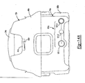
- the housing 40e may be configured so as to define a recess 41e into which the power switch 68e is disposed.
- the power switch 68e is a toggle switch.
- the canister assembly 14e preferably includes a canister 100e and an over-center cam latching system 102e that employs a pair of over-center cam latches 700 to releasably secure the canister 100e to the powerhead assembly 12e.
- the particular canister 100e illustrated has a capacity of about 7.57 litres (two gallons), but those skilled in the art will appreciate that the canister 100e may in the alternative have a capacity that is larger or smaller.
- the canister assembly 14e also includes a reservoir emptying means 101e that permits a liquid to be emptied from the interior of the canister 100e without removing the powerhead assembly 12e from the canister assembly 12e.
- the reservoir emptying means 101e may be a valve (not shown), such as a ball valve or gate valve.
- the reservoir empting means 101e includes a threaded boss 101-1, a gasket 101-2 and a threaded cap 101-3.
- the threaded boss 101-1 extends outwardly from the canister 100e and is threaded about at least a portion of its exterior surface.
- the threaded cap 101-3 includes an internal thread that is configured to threadably engage the threaded boss 101-1.
- the gasket 101-2 which is formed from a resilient, elastomeric material in the example provided, is disposed between the end of the threaded boss 101-1 and an interior surface of the threaded cap 101-3; the gasket 101-2 sealingly engages the end of the threaded boss 101-1 and the threaded cap 101-3 when the threaded cap 101-3 is tightened against the threaded boss 101-1.
- the filter system 16e may be configured to be carried entirely by the powerhead assembly 12e as is shown in Figure 15 .
- the filter system 16e includes a shut-off device 740, a primary filter 114e and an optional secondary filter 116e.
- the secondary filter 116e may be a pad of fibrous material that is coupled to the fan inlet 742, but it could also be made of a mesh or screen material or omitted altogether depending upon the filtering capabilities of the primary filter 114e.
- the secondary filter 116e may be coupled to the power head assembly 12e at a point after (downstream) of the fan 44e.
- the shut-off device 740 is associated with the powerhead assembly 12e and configured to prevent the fan 44e from drawing a liquid into the fan inlet 742 when a volume of liquid in the canister assembly 14e exceeds a predetermined volume.
- the shut-off device 740 may be configured in various ways and may, for example, prevent electrical power from being transmitted to the motor 42e or close-off the fan inlet 742 in response to a volume of liquid in the canister assembly 14e increasing above the predetermined volume.
- the shut-off device 740 includes a plenum 110e and a float 112e.
- the plenum 110e may be a hollow, cage-like construction that permits air to flow therethrough and which serves to retain and guide the float 112e along a generally vertical axis.
- the float 112e which is illustrated in the example provided as being a hollow sphere, is configured to rise automatically within the plenum 110e to close off the fan inlet 742e (to thereby halt the flow of air into the fan 44e and through the powerhead assembly 12e) when liquid in the canister 100e reaches a predetermined level.
- the float 112e may be configured with a shape that may not be spherical or even closed.
- the float 112e may have a generally cylindrical shape that is closed on a single end.
- the primary filter 114e may include a filter body 760, an internal support structure 762, a lower end cap 764 and an upper end cap 766.
- the filter body 760 may be formed from any appropriate filter material, including paper or fabric.
- the filter body is formed from a pleated material that is air and vapor permeable, but resistant to the infiltration or penetration of liquids therethrough so that the filter body 760 may be readily cleaned as through washing.
- the material from which the filter body 760 is made is also hydrophobic and/or oleophobic so that the filter body 760 will not be wetted by water and/or oils that are drawn into the canister assembly 14e.
- one particularly suitable material for the filter body 760 is comprised of a filter media support bonded to a porous expanded PTFE membrane, with one such suitable material being marketed as Gore Wet/Dry Filter Products manufactured by W. L. Gore & Associates, a Delaware Corporation having a place of business in Elkton, Maryland.
- the filter body 760 may be configured to provide HEPA (high efficiency particulate air) filtration or ULPA (ultra low penetration air) filtration.
- the internal support structure 762 may be a cage-like structure that is disposed about the interior of the filter body 760 and fixedly coupled to one or both of the lower and upper end caps 764 and 766.
- the internal support structure 762 is configured to axially and radially support the filter body 760 during the operation of the vacuum 10e to thereby prevent the filter body 760 from crushing or distorting in response to a pressure differential between the interior and exterior surfaces of the filter body 760.
- the lower end cap 764 may be a plate-like structure that is formed from a rigid material and is sealingly bonded to a lower end of the filter body 760. Alternatively, the lower end cap 764 may be wholly or partially formed from the material from which the filter body 760 is manufactured.
- the upper end cap 766 may be an annular flange that is sealingly bonded to an upper end of the filter body 760.
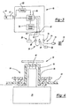
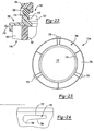
- the upper end cap 766 preferably includes a body 770 that defines a receiving aperture 772, which receives the plenum 110e therethrough when the primary filter 114e is coupled to the powerhead assembly 12e, a seal engagement structure 774, which is illustrated as extending axially from the body 770 and oriented generally concentric with the receiving aperture 772, and a plurality of retaining tabs 776 that are circumferentially spaced about the perimeter of the body 770 and which extend radially outward therefrom.
- the seal engagement structure 774 is sized to engage a corresponding filter gasket 780 that is formed from an elastomeric material and disposed about the fan inlet 742 adjacent a lower surface of the housing 40e.
- the filter gasket 780 is fixedly coupled to the housing 40e, but could alternatively be fixedly coupled to the upper end cap 766 or removably coupled to either the housing 40e or the upper end cap 766.
- the retaining tabs 776 may be configured to matingly engage corresponding retaining slots 790 that are formed in the housing 40e in an area proximate the fan inlet 742.
- the retaining tabs 776 are illustrated as having a generally flat upper surface 792, a tapered lower surface 794 and an engagement feature 796.
- the retaining slots 790 may be formed in the inner surface 800 of a collar 802 that extends generally perpendicularly from the bottom surface of the housing 40e concentric to the fan inlet 742.
- Each retaining slot 790 may be generally L-shaped, with a first portion 810, which is configured to axially receive a corresponding one of the retaining tabs 776, and a second portion 812 that extends around a portion of the circumference of the collar 802.
- the second portion 812 includes an engagement surface 814 that is configured to engage the lower surface 794 of a corresponding one of the retaining tabs 776.
- the engagement surface 814 is tapered and includes a notch-like retaining feature 816 that is configured to receive therein the engagement feature 796 of a corresponding one of the retaining tabs 776.
- the primary filter 114e when the primary filter 114e is to be coupled to the housing 40e, the primary filter 114e is installed over the plenum 110e and the retaining tabs 776 are each inserted to the first portion 810 of an associated retaining slot 790. The primary filter 114e may then be rotated to move the retaining tabs 776 into the second portion 812 of the retaining slots 790.
- the engagement features 796 of each of the retaining tabs 776 are coupled with an associated retaining feature 816 (i.e., received into an associated retaining feature 816 in the particular example provided) to thereby hinder opposite rotation of the primary filter 114e so that the primary filter 114e will not disengage the housing 40e during the operation of the vacuum 10e.
- the tapered lower surface 794 on the retaining tabs 776 and the tapered engagement surface 814 cooperate when the primary filter 114e is being rotated so as to translate the primary filter 114e axially toward the housing 40e.
- the seal engagement structure 774 is forced into sealing engagement with the filter gasket 780 to thereby inhibit the introduction of liquids into the fan 44e from a point between the upper end cap 766 and the housing 40e.
- the ability to seal the primary filter 114e against the housing 40e is of particular importance in those instances where a HEPA or ULPA filter material is employed for the filter body 760, since the filter gasket 780 also inhibits debris from infiltrating between the housing 40e and the upper end cap 766.
- both the second portion 812 of the retaining slots 790 and the tapered lower surfaces 794 of the retaining tabs 776 are tapered in a way that not only facilitates axial movement of the primary filter 114e as the primary filter 114e is rotated relative to the housing 40e but also distributes the load that is exerted by the resilient filter gasket 780 over the entire width of the retaining tabs 776.
- the lower surface 794 of the retaining tabs 776 need not be tapered, and that the retaining tabs 776 and retaining slots 790 could, in the alternative, be formed on the housing 40e and the upper end cap 766, respectively.
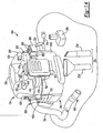
- the hose assembly 18e is preferably a flexible vacuum hose which may be removably coupled to either the inlet port 50e or the outlet port 52e.
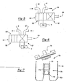
- the hose assembly 18e preferably includes a coupling end 850 with a tapered cylindrical body 852 and a pair of attachment lugs 854.
- the tapered cylindrical body 852 is constructed to be inserted into and frictionally engage a desired one of the inlet and outlet ports 50e and 52e.
- the attachment lugs 854 extend outwardly from the tapered cylindrical body 852 and are configured to be received into corresponding lug slots 860 formed in the walls of the inlet and outlet ports 50e and 52e.
- each of the lug slots 860 may be L- or J-shaped having an insertion portion 864, which receives an associated one of the attachment lugs 854 when the coupling end 850 is axially inserted into the associated inlet or outlet port 50e or 52e, and a retaining portion 866, which extends around a portion of the inner circumference of the associated inlet or outlet port 50e or 52e.
- the terminal end 868 of the retaining portion 866 is somewhat elongated in a direction that is generally parallel to the insertion portion 864 so that when an attachment lug 854 is disposed therein and a force is applied to the hose assembly 18e that tends to withdraw it from the powerhead assembly 12e, the attachment lug 854 is able to move forwardly somewhat.
- the exemplary coupling end 850 illustrated must be further inserted to the port and rotated to effect the uncoupling of the hose assembly 18e from the powerhead assembly 12e. The need to both further insert and rotate the coupling end 850 aids in resisting the uncoupling of the hose assembly 18e from the port at an undesired time.
- the opposite end 880 of the hose assembly 18e may be friction-fittable to any of the hose-end attachments 20e.
- hose-end attachments 20e are well known in the art and as such, a detailed discussion of their construction and use need not be provided herein.
- the vacuum 10e preferably includes a tool retainer 890 that may be integrally formed with the housing 40e or discretely formed and coupled to the housing 40e, as with screws (not shown).
- the tool retainer 890 includes a pair of cylindrical recesses 900, which are configured to receive therein a crevice tool 20e' and a nozzle 20e", and a C-shaped collar 802 that is configured to frictionally engage (i.e., clamp about the perimeter of) the hose assembly 18e.
- the user may store the hose assembly 18e in a storage position as shown in Figure 28 by inserting the coupling end 850 of the hose assembly 18e to the inlet port 50e, wrapping the hose assembly 18e about a lateral side of the vacuum 10e such that the hose assembly 18e is captured below the battery enclosure 550 and lid 552 and clipping a portion of the hose assembly 18e into the C-shaped collar 802.
- the opposite end 880 of the hose assembly 18e is maintained in a stationary position, which may have additional utility in situations where the vacuum 10e is being operated to remove debris from an object and the user of the vacuum 10e is using one hand to hold an object and the other hand to aid in clearing debris from the object.
- the C-shaped collar 802 may be used as a "third hand" to hold the opposite end 880 of the hose assembly 18e as necessary.
- the portion of the hose assembly 18e between the C-Shaped collar 802 and the coupling end 850 i.e., the body of the hose assembly 18e
- the portion of the hose assembly 18e between the C-Shaped collar 802 and the coupling end 850 is in a state of tension (owing to the stretchy nature of the body of the hose assembly 18e) so that the body of the hose assembly 18e is secured to the housing 40 and canister 100e when the hose assembly 18e is placed in the storage position.
- the coupling end 850 of the hose assembly 18e may be inserted to one of the inlet and outlet ports 50e and 52e, the hose assembly 18e wrapped about a lateral side of the vacuum 10e such that the hose assembly 18e is captured below the battery enclosure 550 and lid 552 and the opposite end 880 coupled to the other one of the inlet and outlet ports 50e and 52e as is illustrated in Figure 29 .
- the portion of the hose assembly 18e between the opposite end 880 and the coupling end 850 i.e., the body of the hose assembly 18e
- the portion of the hose assembly 18e between the opposite end 880 and the coupling end 850 is in a state of tension (owing to the stretchy nature of the body of the hose assembly 18e) so that the body of the hose assembly 18e is secured to the housing 40 and canister 100e when the hose assembly 18e is placed in this storage position.
- the shoulder strap 22e may be coupled to the powerhead assembly 12e to permit the user of the wet/dry vacuum 10e to selectively wear the unit over their shoulder so that their hands may be used for other tasks, including transporting other equipment or manipulating the hose assembly 18e when the wet/dry vacuum 10e is in use.
- the shoulder strap 22e is coupled to the two clips 920 that extend from the housing 40e in areas proximate the inlet and outlet ports 50e and 52e.
- an optional cord wrap 930 is also included with the vacuum 10e.
- the cord wrap 930 comprises two L-shaped brackets 960 that are coupled to the housing 40e.
- the brackets 960 include a large flange 962 that is spaced apart from the housing 40e to define therebetween a cord-wrap cavity 964 about which the electrical cord 24e may be wrapped for storage.
- a tool set constructed in accordance with the teachings of the present invention is generally indicated by reference numeral 1000.
- the tool set 1000 includes various power tools 1002 and the above-described utility vacuum 10e, which includes the battery pack 28e.
- Each of the power tools 1002 are of a construction that includes a receptacle assembly 64e with a configuration that is compatible and preferably similar or identical to the receptacle assembly 64e of the utility vacuum 10e to thereby permit the battery pack 28e to be selectively coupled to a given one of the power tools 1002 to transmit electrical power thereto for the operation of the given power tool 1002.
- the battery pack 28e may be selectively coupled to any of the components of the tool set 1000 to thereby power the selected power tool 1002 or the utility vacuum 10e.
- the particular power tools 1002 are illustrated to include a drill driver 1002a, a circular saw 1002b, a reciprocating saw 1002c and a flashlight 1002d, those skilled in the art will appreciate in light of this disclosure that the particular power tool may be of any desired type and may include, for example, hammer drills, jig saws, screw drivers, impact wrenches, rotary hammers, routers, spiral saws, plate joiners, metal working shears, grinders, sanders, buffers, self-leveling rotary lasers, manually-leveled rotary lasers and heavy-duty audio equipment.
Abstract
Description
- This application claims the benefit of
U.S. Provisional Application No. 60/425,371 - The present invention generally relates to vacuum appliances and more particularly to an AC/DC powered hand-portable wet/dry vacuum having improved convenience and performance.
- Vacuum appliances that are capable of picking up both wet and dry materials are commonly known as wet/dry vacuums. Such wet/dry vacuums are well known in the art and are commercially available in a variety of sizes and configurations. Recent consumer trends have placed significant cost pressures the commercially available wet/dry vacuums and as such, many manufacturers are presently producing low-end, relatively small capacity low-cost units and/or high-end, relatively high capacity high-cost professional grade units.
- The low-end, low-cost units are frequently employed by professional users, such as installers, service technicians and trades people in residential construction. These professionals are commonly required to clean their job site prior to leaving for their next job and as such, they frequently prefer the smaller size and portability that are typical of these units. These units, however, are known to have several drawbacks.
- One such drawback relates to convenience of the known wet/dry vacuums and in particular the relatively long amount of time that is necessary for their set-up, the frequency with which the hose becomes disconnected during transport or use and the frequency with which the attachments are lost. Due to the relative bulk of the known wet/dry vacuums and their attachments, the professional user frequently makes a dedicated trip to transport the wet/dry vacuum to or from a jobsite.
- Another drawback relates to the availability of electrical power on a given jobsite. In new residential construction, it is relatively common to encounter a jobsite where electrical power from an electrical utility is unavailable. In some situations, it may be possible to acquire electrical power from a nearby location (e.g., a neighbor) through long, heavy extension cords. Alternatively, a portable generator is required. The inconvenience of heavy extension cords and the expense and inconvenience of a portable generator is highly undesirable to a professional user, particularly considering that the professional user frequently uses the wet/dry vacuum for less than 10 minutes on a given jobsite.
- Yet another drawback concerns the filter system of the known wet/dry vacuums. These filter systems typically employ a disposable filter that is fixedly attached to the lid of the vacuum or some other supporting structure that fits around and covers the fan. When clogged, the disposable filter can severely limit the flow of air through the fan, which significantly impairs the ability of the wet/dry vacuum to pick up debris. Often times, however, a replacement filter is not available to the professional user so that the wet/dry vacuum is simply used at reduced efficiency. Other drawbacks of the known filtering systems include the inconvenience of servicing a filter, which usually entails disassembly of the wet/dry vacuum so as to expose the jobsite to the contents of the canister, and insufficient filtering that results in the discharge of dust from the wet/dry vacuum when the wet/dry vacuum is turned on.
-
CH-A-575548 - Accordingly, there remains a need in the art for a wet/dry vacuum having improved convenience and performance.
- According to an aspect of the present invention, there is provided a utility vacuum comprising the features of claim 1.
- Further areas of applicability of the present invention will become apparent from the detailed description provided hereinafter. It should be understood that the detailed description and specific examples, while indicating the preferred embodiment of the invention, are intended for purposes of illustration only and are not intended to limit the scope of the invention.
- Additional advantages and features of the present invention will become apparent from the subsequent description and the appended claims, taken in conjunction with the accompanying drawings, wherein:
-
Figure 1 is a perspective view of a wet/dry utility vacuum constructed in accordance with the teachings of the present invention; -
Figure 2 is an exploded view of the wet/dry vacuum ofFigure 1 ; -
Figure 3 is a schematic illustration of a portion of the wet/dry vacuum ofFigure 1 illustrating the controller and charging circuit in detail; -
Figure 4 is a sectional view of a portion of the wet/dry vacuum ofFigure 1 illustrating the receptacle assembly in greater detail; -
Figure 5 is a schematic view of the wet/dry vacuum ofFigure 1 illustrating the flow path when the wet/dry vacuum is used in the vacuuming mode; -
Figure 6 is a schematic view of the wet/dry vacuum ofFigure 1 illustrating the flow path when the wet/dry vacuum is used in the blowing mode; -
Figure 7 is a sectional view of a second wet/dry vacuum constructed in accordance with the teachings of the present invention; -
Figure 8 is a sectional view of a third wet/dry vacuum constructed in accordance with the teachings of the present invention; -
Figure 9 is a sectional view similar toFigure 8 but illustrating the powerhead assembly in a raised condition and the canister assembly removed from the housing; -
Figure 10 is a sectional view of a fourth wet/dry vacuum constructed in accordance with the teachings of the present invention; -
Figure 11 is a sectional view similar toFigure 10 but illustrating the canister assembly removed from the housing; -
Figure 12 is a sectional view of a fifth wet/dry vacuum constructed in accordance with the teachings of the present invention; -
Figure 13 is a sectional view similar toFigure 12 but illustrating the secondary filter in a removed condition; -
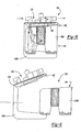
Figure 14 is a perspective view of a sixth wet/dry vacuum constructed in accordance with the teachings of the present invention; -
Figure 14A is a front elevation view of the wet/dry vacuum ofFigure 14 ; -
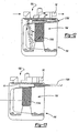
Figure 15 is a longitudinal section view of the wet/dry vacuum ofFigure 14 ; -
Figure 16 is an enlarged portion ofFigure 15 illustrating the cooling inlet aperture in greater detail; -
Figure 17 is an enlarged portion ofFigure 15 illustrating the cooling outlet aperture in greater detail; -
Figure 18 is a schematic view of a portion of the wet/dry vacuum ofFigure 14 illustrating the controller in greater detail; -
Figure 19 is a perspective view of the wet/dry vacuum ofFigure 14 illustrating the lid in a lowered condition and the battery pack exploded from the battery pack enclosure; -
Figure 20 is a schematic view of a portion of the wet/dry vacuum of 14 illustrating the power supply in greater detail; -
Figure 21 is a schematic view of a portion of the wet/dry vacuum ofFigure 14 illustrating the switching device in greater detail; -
Figure 21A is a schematic view similar to that ofFigure 21 but illustrating an alternately constructed controller; -
Figure 22 is an enlarged portion ofFigure 15 illustrating the primary filter in greater detail; -
Figure 23 is a top plan view of the primary filter; -
Figure 24 is a side elevation view of a portion of the primary filter illustrating the configuration of the retaining tab in greater detail; -
Figure 25 is a bottom view of a portion of the wet/dry vacuum ofFigure 14 illustrating the housing of the powerhead assembly in greater detail; -
Figure 26 is a side elevation view of a portion of the housing of the powerhead assembly illustrating one of the retaining slots in greater detail; -
Figure 27 is a top plan view of a portion of the wet/dry vacuum ofFigure 14 illustrating the coupling end of the hose assembly in greater detail; -
Figure 28 is a rear elevation view of the wet/dry vacuum ofFigure 14 illustrating the hose assembly in a first stored condition; -
Figure 29 is a view similar to that ofFigure 28 but illustrating the hose assembly in a second stored condition; -
Figure 30 is a top view of a portion of the wet/dry vacuum illustrating the electrical cord in a stored condition; and -
Figure 31 is a perspective view of a tool set constructed in accordance with the teachings of the present invention. - With reference to
Figure 1 of the drawings, a hand-portable wet/dry vacuum constructed in accordance with the teachings of the present invention is generally indicated byreference numeral 10. In the particular example illustrated, thevacuum 10 is shown to include apowerhead assembly 12, acanister assembly 14, afilter system 16, ahose assembly 18, a plurality of conventional hose-end attachments 20, ashoulder strap 22, a firstelectrical cord 24, a secondelectrical cord 26 and abattery pack 28. - With additional reference to
Figure 2 , thepowerhead assembly 12 may be removably attached to thecanister assembly 14 and includes ahousing 40, amotor 42, afan 44 and acontroller 46. Thehousing 40 defines aninlet port 50, anoutlet port 52, ahandle 54 and acentral cavity 56 into which themotor 42,fan 44 andcontroller 46 are housed. Theinlet port 50 may be routed to thecanister assembly 14 on a first side of thefilter system 16 while theoutlet port 52 may be routed to thecanister assembly 14 on a second side of thefilter system 16. Air flowing into theinlet port 50 flows into thecanister assembly 14 and through thefilter system 16 prior to being directed out of theoutlet port 52. Themotor 42 and thefan 44, which is coupled for rotation with the output shaft (not shown) of themotor 42, cooperate to blow air out of theoutlet port 52 to thereby draw air into thepowerhead assembly 12 via theinlet port 50. - In
Figure 3 , thecontroller 46 is illustrated to preferably include a firstelectrical socket 60, a secondelectrical socket 62, areceptacle assembly 64, apower supply 66, apower switch 68 and acharger circuit 70. Each of the first and secondelectrical sockets receptacle assembly 64 are electrically coupled to thepower supply 66 and configured to conduct electrical power thereto as will be described in detail, below. Thepower supply 66 is electrically coupled to themotor 42 and thepower switch 68 in a conventional manner to permit the user to selectively enable or disable the flow of electrical power to themotor 42. - The first
electrical cord 24 preferably includes a conventionalpronged plug end 74, which is configured to be electrically coupled to a conventionalelectrical outlet 76, and a conventional first connector-end 78 that is configured electrically coupled to the firstelectrical socket 60. Accordingly, the firstelectrical cord 24 permits the user of the wet/dry vacuum 10 to couple thepower supply 66 to a source of alternating current (AC) power. - The second
electrical cord 26 preferably includes a conventional cylindrical plug-end 84, which is configured to be electrically coupled to a conventional cigarettelighter socket 86 of an automotive vehicle, and a conventional second connector-end 88, which is configured to be electrically coupled to the secondelectrical socket 62. Accordingly, the secondelectrical cord 26 permits the user to couple thepower supply 66 to a source of direct current (DC) power, such, as to the electrical system and battery of an automotive vehicle. - In the example of
Figures 3 and 4 , thereceptacle assembly 64 is illustrated as being flexibly connected to thehousing 40 via aflexible gasket 90. Preferably, thegasket 90 is made of a flexible resilient material, such as rubber or another elastomer. Thereceptacle assembly 64 includes areceptacle housing 94, which is configured to receive thebattery pack 28, and aconnector 96 that is floatingly disposed in thereceptacle housing 94 to minimize the shock received by abattery pack 28 if the wet/dry vacuum 10 is dropped. Theconnector 96 has a plurality of terminals (not shown) with a configuration that contacts the associated terminals (not shown) of thebattery pack 28. Preferably, thebattery pack 28, terminals, -receptacle housing 94 andconnector 96 are configured in the manner disclosed inU.S. Patent No. 5,144,217 . Accordingly, thereceptacle assembly 64 permits the user to couple thepower supply 66 to thebattery pack 28 so that the wet/dry vacuum 10 may be operated without either of the first and secondelectrical cords power supply 66 is compatible with battery packs having various different voltages (e.g., 18v, 14v, 12v, and/or 9.6v) in a manner that is well known in the art. Those skilled in the art will appreciate that any manual or automatic means may be employed to select the source of power for the wet/dry vacuum 10. For example, a conventional rotary switch may be provided to permit the user to manually select between AC power, DC power (from the second power cord 26) and abattery pack 28. Alternatively, an automatic switch (comprising transistors or any other suitable electrical device) may be employed such that thepower supply 66 will "look" for one power type, such as AC power, first, and should it not be available, look for "DC" power from thesecond power cord 26 next and thereafter from thebattery pack 28. - In
Figure 3 , thecharger circuit 70 is coupled to thepower supply 66 and thereceptacle assembly 64 in a manner that is well known in the art. Thecharger circuit 70 allows for the charging of battery packs having different voltages, as is well known in the art. An example of a suitable charger circuit is disclosed inU.S.. - Patent No. 6,427,070 . - Accordingly, a user can charge a
battery pack 28, when themotor 42 is not running, by placing thebattery pack 28 in thereceptacle assembly 64 such that the terminals of theconnector 96 electrically engage the associated terminals of thebattery pack 28 and providing the wet/dry vacuum 10 with another source of electrical power via one of the first and secondelectrical cords battery pack 28 may then be removed from thereceptacle assembly 64 and employed to power another device, such as the heavy-duty audio equipment ofU.S. Patent No. 6,427,070 or the cordless drill/driver ofU.S. Patent No. 6,431,289 . - Returning to
Figure 2 , thecanister assembly 14 preferably includes acanister 100 and alatching system 102 that releasably secures thecanister 100 to thepowerhead assembly 12. The particular canister illustrated has a capacity of about 7.57 litres (two gallons), but those skilled in the art will appreciate that thecanister 100 may in the alternative have a capacity that is larger or smaller. - The
filter system 16 may be completely attached to thepowerhead assembly 12 but in the particular example provided, is carriedcanister 100 and includes aplenum 110 that is releasably attachable to thepowerhead assembly 12, afloat ball 112, aprimary filter 114 and asecondary filter 116. Theplenum 110 may have a hollow, cage-like construction that permits air to flow therethrough. Theplenum 110 serves to retain and support theprimary filter 114 as well as retain and guide thefloat ball 112 in a generally vertical orientation. Thefloat ball 112 rises automatically within theplenum 110 to close off thefilter system 16 from the fan 44 (which cuts off the flow of air through the powerhead assembly 12) when liquid in thecanister 100 reaches a predetermined level. - The
primary filter 114 may include a filter structure (not specifically shown), which is formed from a rigid plastic material, and a fabric filter material (not specifically shown) that completely surrounds at least side of the filter structure. The fabric filter material is preferably formed of a washable filter material so as to permit theprimary filter 114 to be washed when loaded with dust or dirt, rather than disposed of and replaced. As those skilled in the art will appreciate, however, theprimary filter 114 may be made of any suitable filtering material, including an open-cell foam or a conventional filter paper (in which case theprimary filter 114 would be disposable). Optionally, a pre-filter structure (not shown) may also be employed. Suitable pre-filter structures include wire mesh or plastic screens, or open-cell foam which serve to collect dust and dirt (e.g., drywall dust) before the dust-carrying airflow contacts theprimary filter 114. - The
secondary filter 116, which is optional and in the particular example provided carried by thepowerhead assembly 12, is disposed upstream of theprimary filter 114 and is of a generally finer mesh or porosity so as to collect relatively small dust particles before they are expelled through theoutlet port 52. Thesecondary filter 116 is preferably removable from thefilter system 16 without disassembling the canister assembly from thepowerhead assembly 12. In the example provided, anaccess port 130 is formed in thehousing 40 between theprimary filter 114 and thefan 44. When thesecondary filter 116 is received into theaccess port 130, agasketed door 132 that may be hingedly coupled to thehousing 40 is closed to seal theaccess port 130 and ensure that air flowing to thefan 44 encounters theprimary filter 114 and then thesecondary filter 116. The purpose of thesecondary filter 116 is to provide very fine filtering of the air passing through the wet/dry vacuum 10 so that dirt and dust are not expelled from theoutlet port 52 when the wet/dry vacuum 10 is operated. Preferably, the wet/dry vacuum 10 may also be used without thesecondary filter 116 when the expelling of relatively fine dust from theoutlet port 52 is not an issue. - With reference to
Figures 1 and2 , thehose assembly 18 is preferably a flexible vacuum hose which is fixedly coupled to theinlet port 50. Also preferably, thehose assembly 18 is at least partially retractable into theinlet port 50 so as to provide a convenient means for storage of thehose assembly 18. Alternatively, thehose assembly 18 may be removably friction fitted on a selective basis to the inlet port 50 (for vacuuming) or the outlet port 52 (for blowing). - The distal end of the
hose assembly 18 may be friction-fittable to any of the hose-end attachments 20. Such hose-end attachments 20 are well known in the art and as such, a detailed discussion of their construction and use need not be provided herein. To prevent the hose-end attachments 20 from being lost, a plurality of receivingslots 140 may be formed into thehousing 40 and/orcanister 100. The receivingslots 140 may be constructed to frictionally engage an associated one of the hose-end attachments 20. When not in use, each hose-end attachment 20 may be coupled to thehousing 40 and/orcanister 100 via its associated receivingslot 140. - The
shoulder strap 22, which is optional, is coupled to thepowerhead assembly 12 and permits the user of the wet/dry vacuum 10 to wear the unit over their shoulder so that their hands may be used for other tasks, including transporting other equipment or manipulating thehose assembly 18 when the wet/dry vacuum 10 is in use. In the particular embodiment illustrated, theshoulder strap 22 is coupled to thehandle 54, which is integrally formed with thehousing 40. - As noted above, the
hose assembly 18 is preferably fixedly coupled to theinlet port 50 and as such, is not connectable to theoutlet port 52 so that the wet/dry vacuum 10 can be used as a blower in a conventional manner (i.e., by connecting thehose assembly 18 to the outlet port 52). As best shown inFigures 1 ,5 and 6 , the wet/dry vacuum 10 may include avalve assembly 150 that selectively controls the flow of air to thefan 44. More specifically, thevalve assembly 150 may be a two-position four-way valve that includes anactuator 154 and avalve element 156. In the particular embodiment illustrated, theactuator 154 is a rotary style actuator that is movable between afirst setting 160 and asecond setting 162. Thevalve element 156 is coupled for rotation with theactuator 154 such that when theactuator 154 is positioned in thefirst setting 160, air is drawn from theinlet port 50 through thefilter system 16 and into thefan 44 in the manner described above. When theactuator 154 is positioned in thesecond setting 162, thevalve element 156 moves (e.g., rotates in the example provided) to cause theoutlet port 52 to be in fluid communication with the inlet side of thefilter system 16 and theinlet port 50 to be in fluid communication with the discharge side of thefan 44. - As those skilled in the art will appreciate, various components of the wet/
dry vacuum 10, such as themotor 42, thefan 44 and theprimary filter 114, may be constructed and/or arranged in a manner that is well known in the art. Such components, constructions and arrangements are illustrated and discussed, for example, inU.S. Patent No. 6,363,574 . - With reference to
Figure 7 , a second wet/dry vacuum constructed in accordance with the teachings of the present invention is generally indicated byreference numeral 10a. Although schematically illustrated, the wet/dry vacuum 10a is generally similar to the wet/dry vacuum 10 ofFigure 1 except that the filter system .. 16a is integrated with thecanister assembly 14a. More specifically, theplenum 110a is coupled to thecanister 100a and theprimary filter 114a completely shrouds theplenum 110a. When thepowerhead assembly 12a is coupled to thecanister assembly 14a, agasket 170 is compressed between theprimary filter 114a and thepowerhead assembly 12a to thereby sealingly engage theprimary filter 114a to thepowerhead assembly 12a. - When the
canister 100a is to be emptied, thepowerhead assembly 12a is unlatched from thecanister 100a, theprimary filter 114a is removed from thecanister 100a and thecanister 100a may be overturned to empty its contents. Like theprimary filter 114, theprimary filter 114a is preferably at least partially constructed from a washable and re-usable filtering material to thereby eliminate the need for replacement filters. This configuration is advantageous in that all of the dirty components are located together and remain in an upright condition when they are being removed. In contrast to the known wet/dry vacuums wherein the filter system is coupled to the powerhead, dust and other debris remain contained within thecanister 100a when thepowerhead assembly 12a is removed. Furthermore, removal and/or replacement of theprimary filter 114a is quick and efficient, as no fasteners are employed to fix the position of theprimary filter 114a relative to thepowerhead assembly 12a. - With reference to
Figures 8 and 9 , another wet/dry vacuum constructed in accordance with the teachings of the present invention is generally indicated byreference numeral 10b. Although schematically illustrated, the wet/dry vacuum 10b is generally similar to the wet/dry vacuum 10a ofFigure 7 except that thepowerhead assembly 12b is pivotally (via ahinge 179, for example) attached to a housing 180 that houses thecanister assembly 14b. - When the
canister assembly 14b is to be removed from or inserted into the housing 180, thepowerhead assembly 12b is pivoted upwardly as shown inFigure 9 . Once thecanister assembly 14b is seated within the housing 180, thepowerhead assembly 12b is pivoted downwardly so that agasket 182 that is carried by thepowerhead assembly 12b sealingly engages thecanister 100b. Those skilled in the art will appreciate that thegasket 182 may alternatively be carried by thecanister 100b. Aconventional latch mechanism 183 may be employed to secure thepowerhead assembly 12b to thecanister assembly 14b. - With reference to
Figures 10 and 11 , a fourth wet/dry vacuum constructed in accordance with the teachings of the present invention is generally indicated byreference numeral 10c. Although schematically illustrated, the wet/dry vacuum 10c is generally similar to the wet/dry vacuum 10b ofFigures 8 and 9 except that thepowerhead assembly 12c is fixedly attached to thehousing 180c that houses thecanister assembly 14c. Thecanister assembly 14c is therefore inserted to and removed from thehousing 180c by sliding thecanister assembly 14c into or out of thehousing 180c. - With reference to
Figure 12 and 13 , yet another wet/dry vacuum constructed in accordance with the teachings of the present invention is generally indicated byreference numeral 10d. The wet/dry vacuum 10d is generally similar to the wet/dry vacuum 10c ofFigures 10 and 11 , except that asecondary filter 116d is incorporated into thefilter system 16d. Like thesecondary filter 116 shown inFigure 5 , thesecondary filter 116d may be located between thefan 44 and theprimary filter 114d and is relatively finer in porosity/mesh so that dirt and dust are not expelled from theoutlet port 52 when the wet/dry vacuum 10d is operated. Advantageously, thesecondary filter 116d may be removed and cleaned or replaced without removal of the canister assembly 14d. - With reference to
Figure 14 , a sixth vacuum constructed in accordance with the teachings of the present invention is generally indicated byreference numeral 10e. Thevacuum 10e is shown to preferably include apowerhead assembly 12e, acanister assembly 14e, afilter system 16e, ahose assembly 18e, a plurality of conventional hose-end attachments 20e, ashoulder strap 22e, anelectrical cord 24e and abattery pack 28e. - With additional reference to
Figure 15 , thepowerhead assembly 12e may be removably attached to thecanister assembly 14e and may include ahousing 40e, amotor 42e, afan 44e and acontroller 46e. Thehousing 40e may define one or more of aninlet port 50e, anoutlet port 52e, ahandle 54e and acentral cavity 56e into which themotor 42e,fan 44e andcontroller 46e may be housed. Theinlet port 50e is routed into thecanister assembly 14e on a first side of thefilter system 16e while theoutlet port 52e routes air out of thepowerhead assembly 12e on a second side of thefilter system 16e. Air flowing into theinlet port 50e may flow into thecanister assembly 14e and through thefilter system 16e prior to being directed out of theoutlet port 52e. Themotor 42e and thefan 44e, which is coupled for rotation with the output shaft (not shown) of themotor 42e, cooperate to preferably blow air out of theoutlet port 52e which thereby draws air into thecanister assembly 14e via theinlet port 50e. - In the example provided, the
housing 40e may be configured to aid in the cooling of themotor 42e during its operation. More specifically, thehousing 40e may be configured with one or morecooling inlet apertures 500 and one or morecooling outlet apertures 502, with both of the cooling inlet andoutlet apertures central cavity 56e as will be described in greater detail, below. In the embodiment provided, a singlecooling inlet aperture 500 and a singlecooling outlet aperture 502 are employed. With additional reference toFigures 16 and 17 , thecooling inlet aperture 500 is illustrated as being concentrically disposed about theinlet port 50e to thereby disguise its location on thehousing 40e, but those skilled in the art will appreciate that the cooling inlet aperture(s) 500 may be located at various other locations on thehousing 40e. Thecooling outlet aperture 502 may be located in the portion of thehousing 40e that defines theoutlet port 52e. In the example provided, thecooling outlet aperture 502 extends through a trailingportion 510 of aprotrusion 512 that is formed on thewall 514 of theoutlet port 52e and oriented in a direction such that a longitudinal axis of theprotrusion 512 is generally parallel to the flow of air through theoutlet port 52e. - The
particular vacuum 10e provided is configured such that during its operation, air flows through theoutlet port 52e to create azone 520 of relatively low static pressure proximate thecooling outlet aperture 502, causing air to flow from thecentral cavity 56e through thecooling outlet aperture 502 where it merges with the air flowing through theoutlet port 52e. The air departing from thecentral cavity 56e likewise draws fresh air into thecentral cavity 56e through thecooling inlet aperture 500. The exchange of air in thecentral cavity 56e permits themotor 42e to reject relatively higher levels of heat. More specifically, the air flowing through thecentral cavity 56e provides an air stream permits that flows against themotor 42e to thereby permit themotor 42e to reject heat therefrom with a convective heat transfer mechanism. - In
Figure 18 , thecontroller 46e is illustrated to preferably include areceptacle assembly 64e, apower supply 66e, apower switch 68e and anoptional charger circuit 70e. Thereceptacle assembly 64e is electrically coupled to thepower supply 66e and configured to conduct electrical power thereto as will be described in detail, below. Thepower supply 66e is electrically coupled to themotor 42e and thepower switch 68e to permit the user to selectively enable or disable the flow of electrical power to themotor 42e. - The
electrical cord 24e may include a conventionalpronged plug end 74e, which is configured to be electrically coupled to a conventionalelectrical outlet 76e, and an opposite end (not shown) which is electrically coupled in a conventional manner to thepower supply 66e. Accordingly, theelectrical cord 24e may permit the user of the wet/dry vacuum 10e to couple thepower supply 66e to a source of alternating current (AC) power. - The
receptacle assembly 64e may be generally similar to thereceptacle assembly 64 ofFigures 3 and 4 and as such, need not be discussed in significant detail. In the example provided, thereceptacle assembly 64e is illustrated inFigure 19 to be disposed in abattery enclosure 550 that is coupled to or integrally formed with thehousing 40e. Alid 552 may be hingedly coupled to thebattery enclosure 550 and is movable between a closed position (Figure 14 ), which substantially closes thebattery enclosure 550, and an open position, which substantially clears thebattery enclosure 550. An over-centercamming latch mechanism 556 may be employed to selectively maintain thelid 552 in the closed position. An optionalbattery pack gasket 560 andleaf spring 562 may also be employed. Thebattery pack gasket 560 may be disposed between thebattery pack 28e and one or both of thereceptacle assembly 64e and the battery enclosure 550 (i.e.,battery pack gaskets 560 in the latter example), while theleaf spring 562 may be attached to thelid 552 and positioned so as to push thebattery pack 28e into electrical contact with thereceptacle assembly 64e and sealing contact with thebattery pack gasket 560 when thelid 552 is positioned in the closed position. Thebattery pack gasket 560 inhibits liquids from entering thereceptacle assembly 64e and the interior of thehousing 40e despite the presence of vent apertures 564 (Figure 25 ) that extend through thebattery enclosure 550 and/orlid 552. - The
receptacle assembly 64e permits the user to couple thepower supply 66e to thebattery pack 28e so that the wet/dry vacuum 10e may be operated when, for example, a source of AC electrical power is unavailable or inconvenient to access. Also preferably, thepower supply 66e is compatible with battery packs having various different voltages (e.g., 18v, 14v, 12v, and/or 9.6v). Stated another way, thepower supply 66e is preferably configured such that a first battery pack having a first output voltage and a second battery pack having a second output voltage that is different than the first output voltage may be used interchangeably to power thepower supply 66e. In the particular example provided, thepower supply 66e includes an AC/DC converter 600 and a DC/DC converter 602 as shown inFigure 20 . The AC/DC converter 600 preferably has an electromagneticinterference suppression module 610, arectifier 612 for rectifying alternating current power input thereto from theelectrical cord 24e, and a switchingpower supply 614 for pulse-modulating the rectified (i.e., direct current) power provided by therectifier 612. The switchingpower supply 614 switches (i.e., turns on and off) to control its output to themotor 42e. By controlling the duration of each of the "on" and "off" events, the switchingpower supply 614 is able to apply power of a desired voltage to themotor 42e. Afeedback loop 620 may optionally be included in thepower supply 66e for more accurate control of the voltage. Similarly, the DC/DC converter 602 may include a switchingpower supply 624 that is similar to the switchingpower supply 614 of the AC/DC converter 600 in that it switches (i.e., turns on and off) to control its output to themotor 42e to thereby apply power of a desired voltage,to themotor 42e. Consequently, electrical power of a relatively identical voltage may be provided to themotor 42e regardless of the voltage of thebattery pack 28e. - The
power supply 66e preferably includes aswitch device 630 for automatically selecting the source of power for the wet/dry vacuum 10e. With reference toFigure 21 , theswitch device 630 is illustrated to be optionally integrated with the DC/DC converter 602 and may include, for example, anintegrated circuit 640, first andsecond resistors transistor 646. Theintegrated circuit 640 may be configured such that if it receives power from the AC/DC converter 600, theintegrated circuit 640 will turn thetransistor 646 "off" so that the power from thebattery pack 28e will not be transmitted to themotor 42e. Accordingly, theswitch device 630 may be configured so that thebattery pack 28e will power thevacuum 10e unless thevacuum 10e is coupled to a source of alternating current power in the manner described above. - With brief reference to
Figure 21A , an alternately constructedpower supply 66e' is illustrated. Thepower supply 66e' differs from thepower supply 66e ofFigure 21 in that theswitch device 630 is associated with the AC/DC converter 600. More specifically, theswitch device 630 is illustrated as being a relay 630-1 with first and second contacts 630-2, 630-3, respectively, that are employed to control the flow of electricity. The relay 630-1 is illustrated in its normal condition wherein a lead 630-4 from themotor 42e is electrically coupled to the first contact 630-2, which is in turn electrically coupled to the DC/DC converter 602 (via thepower switch 68e). The relay 630-1 remains in its normal condition unless the AC/DC converter 600 provides power (through thepower switch 68e in the example provided) to the relay 630-1. When thevacuum 10e is coupled to a source of alternating current power and thepower switch 68e is switched on, the relay 630-1 causes the lead 630-4 from themotor 42e to be electrically coupled to the second contact 630-3, which is in turn electrically coupled to the AC/DC converter 600 (via thepower switch 68e). Those skilled in the art will appreciate from this disclosure that the power supply, in its broader aspects, may be constructed somewhat differently and as such, the particular examples described and illustrated in this application are exemplary only and not intended to be limiting in any manner. - Returning to
Figure 18 , thecharger circuit 70e may be coupled to thepower supply 66e and thereceptacle assembly 64e. Thecharger circuit 70e allows for the charging of battery packs having different voltages, as is well known in the art. An example of a suitable charger circuit is disclosed inU.S. Patent Nos. 6,427,070 and6,496,688 . - Accordingly, a user can charge a
battery pack 28e, when thepower supply 66e is coupled to a source of alternating current power by placing thebattery pack 28e in thereceptacle assembly 64e such that the terminals (not shown) of the connector (not shown) of thereceptacle assembly 64e electrically engage the associated terminals (not shown) of thebattery pack 28e. Once charged, thebattery pack 28e may then be employed to power thevacuum 10e or removed from thereceptacle assembly 64e and employed to power another device, such as the heavy-duty audio equipment ofU.S. Patent No. 6,427,070 or the cordless drill/driver ofU.S. Patent No. 6,431,289 . - With brief reference to
Figure 14A , thehousing 40e may be configured so as to define arecess 41e into which thepower switch 68e is disposed. In the particular example provided, thepower switch 68e is a toggle switch. - Returning to
Figure 14 , thecanister assembly 14e preferably includes acanister 100e and an over-centercam latching system 102e that employs a pair of over-center cam latches 700 to releasably secure thecanister 100e to thepowerhead assembly 12e. Theparticular canister 100e illustrated has a capacity of about 7.57 litres (two gallons), but those skilled in the art will appreciate that thecanister 100e may in the alternative have a capacity that is larger or smaller. Preferably, thecanister assembly 14e also includes a reservoir emptying means 101e that permits a liquid to be emptied from the interior of thecanister 100e without removing thepowerhead assembly 12e from thecanister assembly 12e. The reservoir emptying means 101e may be a valve (not shown), such as a ball valve or gate valve. In the particular example provided, the reservoir empting means 101e includes a threaded boss 101-1, a gasket 101-2 and a threaded cap 101-3. The threaded boss 101-1 extends outwardly from thecanister 100e and is threaded about at least a portion of its exterior surface. The threaded cap 101-3 includes an internal thread that is configured to threadably engage the threaded boss 101-1. The gasket 101-2, which is formed from a resilient, elastomeric material in the example provided, is disposed between the end of the threaded boss 101-1 and an interior surface of the threaded cap 101-3; the gasket 101-2 sealingly engages the end of the threaded boss 101-1 and the threaded cap 101-3 when the threaded cap 101-3 is tightened against the threaded boss 101-1. - in contrast to the
filter system 16 ofFigure 1 , thefilter system 16e may be configured to be carried entirely by thepowerhead assembly 12e as is shown inFigure 15 . Thefilter system 16e includes a shut-off device 740, aprimary filter 114e and an optionalsecondary filter 116e. In the example provided, thesecondary filter 116e may be a pad of fibrous material that is coupled to thefan inlet 742, but it could also be made of a mesh or screen material or omitted altogether depending upon the filtering capabilities of theprimary filter 114e. Also, thesecondary filter 116e may be coupled to thepower head assembly 12e at a point after (downstream) of thefan 44e. - The shut-off device 740 is associated with the
powerhead assembly 12e and configured to prevent thefan 44e from drawing a liquid into thefan inlet 742 when a volume of liquid in thecanister assembly 14e exceeds a predetermined volume. The shut-off device 740 may be configured in various ways and may, for example, prevent electrical power from being transmitted to themotor 42e or close-off thefan inlet 742 in response to a volume of liquid in thecanister assembly 14e increasing above the predetermined volume. In the particular example provided, the shut-off device 740 includes aplenum 110e and afloat 112e. Theplenum 110e may be a hollow, cage-like construction that permits air to flow therethrough and which serves to retain and guide thefloat 112e along a generally vertical axis. Thefloat 112e, which is illustrated in the example provided as being a hollow sphere, is configured to rise automatically within theplenum 110e to close off the fan inlet 742e (to thereby halt the flow of air into thefan 44e and through thepowerhead assembly 12e) when liquid in thecanister 100e reaches a predetermined level. Those skilled in the art will appreciate from this disclosure that thefloat 112e may be configured with a shape that may not be spherical or even closed. For example, thefloat 112e may have a generally cylindrical shape that is closed on a single end. - The
primary filter 114e may include afilter body 760, aninternal support structure 762, alower end cap 764 and anupper end cap 766. Thefilter body 760 may be formed from any appropriate filter material, including paper or fabric. In the particular example provided, however, the filter body is formed from a pleated material that is air and vapor permeable, but resistant to the infiltration or penetration of liquids therethrough so that thefilter body 760 may be readily cleaned as through washing. Optionally, the material from which thefilter body 760 is made is also hydrophobic and/or oleophobic so that thefilter body 760 will not be wetted by water and/or oils that are drawn into thecanister assembly 14e. Our testing has shown that one particularly suitable material for thefilter body 760 is comprised of a filter media support bonded to a porous expanded PTFE membrane, with one such suitable material being marketed as Gore Wet/Dry Filter Products manufactured by W. L. Gore & Associates, a Delaware Corporation having a place of business in Elkton, Maryland. Also optionally, thefilter body 760 may be configured to provide HEPA (high efficiency particulate air) filtration or ULPA (ultra low penetration air) filtration. - The
internal support structure 762 may be a cage-like structure that is disposed about the interior of thefilter body 760 and fixedly coupled to one or both of the lower and upper end caps 764 and 766. Theinternal support structure 762 is configured to axially and radially support thefilter body 760 during the operation of thevacuum 10e to thereby prevent thefilter body 760 from crushing or distorting in response to a pressure differential between the interior and exterior surfaces of thefilter body 760. - The
lower end cap 764 may be a plate-like structure that is formed from a rigid material and is sealingly bonded to a lower end of thefilter body 760. Alternatively, thelower end cap 764 may be wholly or partially formed from the material from which thefilter body 760 is manufactured. - The
upper end cap 766 may be an annular flange that is sealingly bonded to an upper end of thefilter body 760. With reference toFigures 15 and22 through 24 , theupper end cap 766 preferably includes abody 770 that defines a receivingaperture 772, which receives theplenum 110e therethrough when theprimary filter 114e is coupled to thepowerhead assembly 12e, aseal engagement structure 774, which is illustrated as extending axially from thebody 770 and oriented generally concentric with the receivingaperture 772, and a plurality of retainingtabs 776 that are circumferentially spaced about the perimeter of thebody 770 and which extend radially outward therefrom. - The
seal engagement structure 774 is sized to engage acorresponding filter gasket 780 that is formed from an elastomeric material and disposed about thefan inlet 742 adjacent a lower surface of thehousing 40e. In the particular embodiment illustrated, thefilter gasket 780 is fixedly coupled to thehousing 40e, but could alternatively be fixedly coupled to theupper end cap 766 or removably coupled to either thehousing 40e or theupper end cap 766. - With additional reference to
Figures 25 and26 , the retainingtabs 776 may be configured to matingly engage corresponding retainingslots 790 that are formed in thehousing 40e in an area proximate thefan inlet 742. In the particular example provided, the retainingtabs 776 are illustrated as having a generally flatupper surface 792, a taperedlower surface 794 and anengagement feature 796. - The retaining
slots 790 may be formed in theinner surface 800 of acollar 802 that extends generally perpendicularly from the bottom surface of thehousing 40e concentric to thefan inlet 742. Each retainingslot 790 may be generally L-shaped, with afirst portion 810, which is configured to axially receive a corresponding one of the retainingtabs 776, and asecond portion 812 that extends around a portion of the circumference of thecollar 802. Thesecond portion 812 includes anengagement surface 814 that is configured to engage thelower surface 794 of a corresponding one of the retainingtabs 776. In the example provided, theengagement surface 814 is tapered and includes a notch-like retaining feature 816 that is configured to receive therein theengagement feature 796 of a corresponding one of the retainingtabs 776. - With reference to
Figures 22, 23 and26 , when theprimary filter 114e is to be coupled to thehousing 40e, theprimary filter 114e is installed over theplenum 110e and the retainingtabs 776 are each inserted to thefirst portion 810 of an associated retainingslot 790. Theprimary filter 114e may then be rotated to move the retainingtabs 776 into thesecond portion 812 of the retainingslots 790. With sufficient rotation of theprimary filter 114e, the engagement features 796 of each of the retainingtabs 776 are coupled with an associated retaining feature 816 (i.e., received into an associatedretaining feature 816 in the particular example provided) to thereby hinder opposite rotation of theprimary filter 114e so that theprimary filter 114e will not disengage thehousing 40e during the operation of thevacuum 10e. - The tapered
lower surface 794 on the retainingtabs 776 and the taperedengagement surface 814 cooperate when theprimary filter 114e is being rotated so as to translate theprimary filter 114e axially toward thehousing 40e. In this way, theseal engagement structure 774 is forced into sealing engagement with thefilter gasket 780 to thereby inhibit the introduction of liquids into thefan 44e from a point between theupper end cap 766 and thehousing 40e. The ability to seal theprimary filter 114e against thehousing 40e is of particular importance in those instances where a HEPA or ULPA filter material is employed for thefilter body 760, since thefilter gasket 780 also inhibits debris from infiltrating between thehousing 40e and theupper end cap 766. - In the particular example provided, both the
second portion 812 of the retainingslots 790 and the taperedlower surfaces 794 of the retainingtabs 776 are tapered in a way that not only facilitates axial movement of theprimary filter 114e as theprimary filter 114e is rotated relative to thehousing 40e but also distributes the load that is exerted by theresilient filter gasket 780 over the entire width of the retainingtabs 776. Those skilled in the art will appreciate, however, that thelower surface 794 of the retainingtabs 776 need not be tapered, and that the retainingtabs 776 and retainingslots 790 could, in the alternative, be formed on thehousing 40e and theupper end cap 766, respectively. - With renewed reference to
Figure 15 and additional reference toFigure 27 , thehose assembly 18e is preferably a flexible vacuum hose which may be removably coupled to either theinlet port 50e or theoutlet port 52e. In the example provided, thehose assembly 18e preferably includes acoupling end 850 with a taperedcylindrical body 852 and a pair of attachment lugs 854. The taperedcylindrical body 852 is constructed to be inserted into and frictionally engage a desired one of the inlet andoutlet ports cylindrical body 852 and are configured to be received intocorresponding lug slots 860 formed in the walls of the inlet andoutlet ports Figures 15 and16 , each of thelug slots 860 may be L- or J-shaped having aninsertion portion 864, which receives an associated one of the attachment lugs 854 when thecoupling end 850 is axially inserted into the associated inlet oroutlet port outlet port terminal end 868 of the retaining portion 866 is somewhat elongated in a direction that is generally parallel to theinsertion portion 864 so that when anattachment lug 854 is disposed therein and a force is applied to thehose assembly 18e that tends to withdraw it from thepowerhead assembly 12e, theattachment lug 854 is able to move forwardly somewhat. As such, theexemplary coupling end 850 illustrated must be further inserted to the port and rotated to effect the uncoupling of thehose assembly 18e from thepowerhead assembly 12e. The need to both further insert and rotate thecoupling end 850 aids in resisting the uncoupling of thehose assembly 18e from the port at an undesired time. - With reference to
Figure 14 , theopposite end 880 of thehose assembly 18e may be friction-fittable to any of the hose-end attachments 20e. Such hose-end attachments 20e are well known in the art and as such, a detailed discussion of their construction and use need not be provided herein. To ensure that the hose-end attachments 20e are secure and handy, thevacuum 10e preferably includes atool retainer 890 that may be integrally formed with thehousing 40e or discretely formed and coupled to thehousing 40e, as with screws (not shown). - In the example provided, the
tool retainer 890 includes a pair ofcylindrical recesses 900, which are configured to receive therein acrevice tool 20e' and anozzle 20e", and a C-shapedcollar 802 that is configured to frictionally engage (i.e., clamp about the perimeter of) thehose assembly 18e. Accordingly, the user may store thehose assembly 18e in a storage position as shown inFigure 28 by inserting thecoupling end 850 of thehose assembly 18e to theinlet port 50e, wrapping thehose assembly 18e about a lateral side of thevacuum 10e such that thehose assembly 18e is captured below thebattery enclosure 550 andlid 552 and clipping a portion of thehose assembly 18e into the C-shapedcollar 802. With thehose assembly 18e thus stowed, theopposite end 880 of thehose assembly 18e is maintained in a stationary position, which may have additional utility in situations where thevacuum 10e is being operated to remove debris from an object and the user of thevacuum 10e is using one hand to hold an object and the other hand to aid in clearing debris from the object. Stated another way, the C-shapedcollar 802 may be used as a "third hand" to hold theopposite end 880 of thehose assembly 18e as necessary. Preferably, the portion of thehose assembly 18e between the C-Shapedcollar 802 and the coupling end 850 (i.e., the body of thehose assembly 18e) is in a state of tension (owing to the stretchy nature of the body of thehose assembly 18e) so that the body of thehose assembly 18e is secured to thehousing 40 andcanister 100e when thehose assembly 18e is placed in the storage position. - Alternatively, the
coupling end 850 of thehose assembly 18e may be inserted to one of the inlet andoutlet ports hose assembly 18e wrapped about a lateral side of thevacuum 10e such that thehose assembly 18e is captured below thebattery enclosure 550 andlid 552 and theopposite end 880 coupled to the other one of the inlet andoutlet ports Figure 29 . Preferably, the portion of thehose assembly 18e between theopposite end 880 and the coupling end 850 (i.e., the body of thehose assembly 18e) is in a state of tension (owing to the stretchy nature of the body of thehose assembly 18e) so that the body of thehose assembly 18e is secured to thehousing 40 andcanister 100e when thehose assembly 18e is placed in this storage position. - Returning to
Figure 14 , theshoulder strap 22e may be coupled to thepowerhead assembly 12e to permit the user of the wet/dry vacuum 10e to selectively wear the unit over their shoulder so that their hands may be used for other tasks, including transporting other equipment or manipulating thehose assembly 18e when the wet/dry vacuum 10e is in use. In the particular embodiment illustrated, theshoulder strap 22e is coupled to the twoclips 920 that extend from thehousing 40e in areas proximate the inlet andoutlet ports - With additional reference to
Figure 30 , anoptional cord wrap 930 is also included with thevacuum 10e. In the example provided, thecord wrap 930 comprises two L-shapedbrackets 960 that are coupled to thehousing 40e. Thebrackets 960 include alarge flange 962 that is spaced apart from thehousing 40e to define therebetween a cord-wrap cavity 964 about which theelectrical cord 24e may be wrapped for storage. - In
Figure 31 , a tool set constructed in accordance with the teachings of the present invention is generally indicated byreference numeral 1000. The tool set 1000 includesvarious power tools 1002 and the above-describedutility vacuum 10e, which includes thebattery pack 28e. Each of thepower tools 1002 are of a construction that includes areceptacle assembly 64e with a configuration that is compatible and preferably similar or identical to thereceptacle assembly 64e of theutility vacuum 10e to thereby permit thebattery pack 28e to be selectively coupled to a given one of thepower tools 1002 to transmit electrical power thereto for the operation of the givenpower tool 1002. Advantageously, thebattery pack 28e may be selectively coupled to any of the components of the tool set 1000 to thereby power the selectedpower tool 1002 or theutility vacuum 10e. While theparticular power tools 1002 are illustrated to include adrill driver 1002a, acircular saw 1002b, areciprocating saw 1002c and aflashlight 1002d, those skilled in the art will appreciate in light of this disclosure that the particular power tool may be of any desired type and may include, for example, hammer drills, jig saws, screw drivers, impact wrenches, rotary hammers, routers, spiral saws, plate joiners, metal working shears, grinders, sanders, buffers, self-leveling rotary lasers, manually-leveled rotary lasers and heavy-duty audio equipment. - While the invention has been described in the specification and illustrated in the drawings with reference to a preferred embodiment, it will be understood by those skilled in the art that various changes may be made and equivalents may be substituted for elements thereof without departing from the scope of the invention as defined in the claims. In addition, many modifications may be made to adapt a particular situation or material to the teachings of the invention without departing from the essential scope thereof. Therefore, it is intended that the invention not be limited to the particular embodiment illustrated by the drawings and described in the specification as the best mode presently contemplated for carrying out this invention, but that the invention will include any embodiments falling within the foregoing description and the appended claims.
Claims (23)
- A hand-portable utility vacuum (10) comprising:a canister (14);a powerhead assembly (12) coupled to the canister and having a fan (44), a motor (42) for providing rotary power to the fan, and a power supply (66) for distributing electrical power to the motor, the fan including a fan inlet (742);a shut-off device (740) associated with the powerhead assembly, the shut-off device being configured to prevent the fan from drawing a liquid into the fan inlet when a volume of the liquid in the canister exceeds a predetermined volume;an electrical cord (24) associated with the power supply, the electrical cord being configured to permit a user to selectively couple the power supply to a source of alternating current power;a first battery (28) associated with the power supply, the first battery being a source of direct current electrical power for powering the power supply when the power supply is not receiving alternating current power from the source of alternating current power, and a second battery (28e) that is interchangeable with the first battery, the second battery having a voltage that is different than a voltage of the first battery, the second battery being the source of direct current electrical power for powering the power supply when the second battery is interchanged with the first battery and the power supply is not receiving alternating current power from the source of alternating current power.
- The utility vacuum of Claim 1, further comprising an electrical cord (26) associated with the power supply, the electrical cord (26) being configured to detachably couple the power supply to a second source of direct current power, the second source of direct current power being distinct and separate from that of the first battery.
- The utility vacuum according to any one of the preceding claims, wherein the first battery is removable from the utility vacuum.
- The utility vacuum according to any one of the preceding claims, wherein the first battery is detachably coupled to the powerhead assembly.
- The utility vacuum of Claim 1, wherein a voltage of the electrical power provided by the first battery is different than a voltage of the direct current power provided by the second source of direct current power.
- The utility vacuum according to any one of the preceding claims, wherein the first battery is housed in a compartment (550), the compartment being defined by the housing and a lid (552), the lid being movable relative to the housing between a first condition, which permits ingress of the first battery to the compartment and egress of the first battery pack from the compartment, and a second condition, in which the first battery is inhibits ingress of the first battery to the compartment and egress of the first battery from the compartment.
- The utility vacuum of Claim 3, further comprising a battery charger (70), the battery charger being electrically coupled to one of the power supply and the electrical cord, the battery charger being operable for charging the first or second battery when the electrical cord is coupled to the source of alternating current power.
- The utility vacuum of Claim 1, wherein the power supply includes a circuit (630, 640) for selecting between the source of alternating current power and the source of direct current power.
- The utility vacuum of Claim 8, wherein the circuit inhibits the first or second battery from transmitting electrical power to the power supply when the power supply is receiving alternating current power.
- The utility vacuum of Claim 9, wherein the power supply includes an AC/DC converter (600) and a DC/DC converter (602).
- The utility vacuum of Claim 10, wherein the AC/DC converter and the DC/DC converter each include a switching power supply (614, 624) to pulse modulate electrical energy to the motor.
- The utility vacuum of Claim 1, wherein the power supply includes at least one switching power supply to pulse modulate electrical energy to the motor.
- The utility vacuum of Claim 1, wherein the powerhead assembly includes a housing (40e) in which the fan, the motor and the power supply are housed, the housing including an inlet (50e) and an outlet (52e), wherein operation of the utility vacuum draws an intake flow of air into the canister through the inlet and discharges a discharge flow of air through the outlet.
- The utility vacuum of Claim 13, wherein a cooling air intake aperture (500) and a cooling air discharge aperture (502) are formed in the housing, the cooling air discharge aperture being associated with the outlet so that air flowing through the outlet blows across the cooling air discharge aperture to set up a zone of relatively low pressure that causes air to be drawn out of the cooling air discharge aperture to thereby cool the motor.
- The utility vacuum of Claim 14, wherein the cooling air intake aperture is positioned proximate the inlet.
- The utility vacuum of Claim 15, wherein the cooling air intake aperture is positioned concentric about the inlet.
- The utility vacuum of Claim 1, wherein the shut-off device (740) includes an object (112e) for blocking the fan inlet.
- The utility vacuum of Claim 17, wherein the object (112e) is a float.
- The utility vacuum of Claim 1, further comprising a flexible hose (18, 18e) that is configured to be coupled to the inlet.
- The utility vacuum of Claim 19, wherein the flexible hose has a first end (850), a second end (880) opposite the first end and a body interconnecting the first and second ends, the flexible hose being positionable in a storage position, wherein the first end is coupled to the inlet and the body is wrapped about a side of the utility vacuum so as to extend under the compartment.
- The utility vacuum of Claim 20, wherein the second end of the flexible hose is coupled to the outlet.
- The utility vacuum of Claim 21, wherein the body is maintained in a state of tension when the hose assembly is positioned in the storage position.
- The utility vacuum of Claim 20, wherein the second end of the flexible hose is configured to be coupled to a clip (890) attached to the housing.
Priority Applications (5)
| Application Number | Priority Date | Filing Date | Title |
|---|---|---|---|
| EP08172529A EP2036480B1 (en) | 2002-11-12 | 2003-11-11 | AC/DC hand portable wet/dry vacuum having improved portability and convenience |
| EP10164370.8A EP2215949B1 (en) | 2002-11-12 | 2003-11-11 | AC/DC Hand Portable Wet/Dry Vacuum Having Improved Portability and Convenience |
| EP07102680A EP1785079A3 (en) | 2002-11-12 | 2003-11-11 | AC/DC hand portable wet/dry vacuum having improved portability and convenience |
| EP10164369.0A EP2215948B1 (en) | 2002-11-12 | 2003-11-11 | AC/DC hand portable wet/dry vacuum having improved portability and convenience |
| EP08167861A EP2014211A3 (en) | 2002-11-12 | 2003-11-11 | AC/DC hand portable wet/dry vacuum having improved portability and convenience |
Applications Claiming Priority (4)
| Application Number | Priority Date | Filing Date | Title |
|---|---|---|---|
| US640267 | 1996-04-30 | ||
| US42537102P | 2002-11-12 | 2002-11-12 | |
| US425371P | 2002-11-12 | ||
| US10/640,267 US7653963B2 (en) | 2002-11-12 | 2003-08-13 | AC/DC hand portable wet/dry vacuum having improved portability and convenience |
Related Child Applications (5)
| Application Number | Title | Priority Date | Filing Date |
|---|---|---|---|
| EP08167861A Division EP2014211A3 (en) | 2002-11-12 | 2003-11-11 | AC/DC hand portable wet/dry vacuum having improved portability and convenience |
| EP10164370.8A Division EP2215949B1 (en) | 2002-11-12 | 2003-11-11 | AC/DC Hand Portable Wet/Dry Vacuum Having Improved Portability and Convenience |
| EP07102680A Division EP1785079A3 (en) | 2002-11-12 | 2003-11-11 | AC/DC hand portable wet/dry vacuum having improved portability and convenience |
| EP10164369.0A Division EP2215948B1 (en) | 2002-11-12 | 2003-11-11 | AC/DC hand portable wet/dry vacuum having improved portability and convenience |
| EP08172529A Division EP2036480B1 (en) | 2002-11-12 | 2003-11-11 | AC/DC hand portable wet/dry vacuum having improved portability and convenience |
Publications (3)
| Publication Number | Publication Date |
|---|---|
| EP1419723A2 EP1419723A2 (en) | 2004-05-19 |
| EP1419723A3 EP1419723A3 (en) | 2004-06-16 |
| EP1419723B1 true EP1419723B1 (en) | 2009-06-17 |
Family
ID=32180021
Family Applications (5)
| Application Number | Title | Priority Date | Filing Date |
|---|---|---|---|
| EP10164369.0A Expired - Lifetime EP2215948B1 (en) | 2002-11-12 | 2003-11-11 | AC/DC hand portable wet/dry vacuum having improved portability and convenience |
| EP10164370.8A Expired - Lifetime EP2215949B1 (en) | 2002-11-12 | 2003-11-11 | AC/DC Hand Portable Wet/Dry Vacuum Having Improved Portability and Convenience |
| EP08172529A Expired - Lifetime EP2036480B1 (en) | 2002-11-12 | 2003-11-11 | AC/DC hand portable wet/dry vacuum having improved portability and convenience |
| EP08167861A Withdrawn EP2014211A3 (en) | 2002-11-12 | 2003-11-11 | AC/DC hand portable wet/dry vacuum having improved portability and convenience |
| EP03025864A Expired - Lifetime EP1419723B1 (en) | 2002-11-12 | 2003-11-11 | AC/DC hand portable wet/dry vacuum having improved portability and convenience |
Family Applications Before (4)
| Application Number | Title | Priority Date | Filing Date |
|---|---|---|---|
| EP10164369.0A Expired - Lifetime EP2215948B1 (en) | 2002-11-12 | 2003-11-11 | AC/DC hand portable wet/dry vacuum having improved portability and convenience |
| EP10164370.8A Expired - Lifetime EP2215949B1 (en) | 2002-11-12 | 2003-11-11 | AC/DC Hand Portable Wet/Dry Vacuum Having Improved Portability and Convenience |
| EP08172529A Expired - Lifetime EP2036480B1 (en) | 2002-11-12 | 2003-11-11 | AC/DC hand portable wet/dry vacuum having improved portability and convenience |
| EP08167861A Withdrawn EP2014211A3 (en) | 2002-11-12 | 2003-11-11 | AC/DC hand portable wet/dry vacuum having improved portability and convenience |
Country Status (8)
| Country | Link |
|---|---|
| US (3) | US7653963B2 (en) |
| EP (5) | EP2215948B1 (en) |
| JP (1) | JP2004160235A (en) |
| CN (1) | CN100479733C (en) |
| AT (1) | ATE433699T1 (en) |
| AU (1) | AU2003261564A1 (en) |
| DE (1) | DE60327976D1 (en) |
| TW (1) | TW200418427A (en) |
Cited By (6)
| Publication number | Priority date | Publication date | Assignee | Title |
|---|---|---|---|---|
| EP2451002A1 (en) | 2010-11-08 | 2012-05-09 | HILTI Aktiengesellschaft | Method and charger for charging at least two batteries |
| EP2451001A1 (en) | 2010-11-08 | 2012-05-09 | HILTI Aktiengesellschaft | Mobile electric device with charge display and battery for same |
| EP2449933A1 (en) | 2010-11-08 | 2012-05-09 | HILTI Aktiengesellschaft | Vacuum cleaner with a cable holder |
| DE102010043580A1 (en) | 2010-11-08 | 2012-05-10 | Hilti Aktiengesellschaft | Vacuum cleaner with a Saugschlauchhalteeinrichtung |
| EP2468166A1 (en) | 2010-12-23 | 2012-06-27 | HILTI Aktiengesellschaft | Vacuum cleaner with tempered accumulator |
| DE102013018278A1 (en) | 2013-10-31 | 2015-04-30 | Metabowerke Gmbh | Multi-purpose vacuum cleaners |
Families Citing this family (166)
| Publication number | Priority date | Publication date | Assignee | Title |
|---|---|---|---|---|
| US6427070B1 (en) * | 1999-03-04 | 2002-07-30 | Black & Decker Inc. | Heavy-duty audio equipment |
| US8319357B2 (en) * | 2002-06-06 | 2012-11-27 | Black & Decker Inc. | Starter system for portable internal combustion engine electric generators using a portable universal battery pack |
| US20050273969A1 (en) * | 2002-11-12 | 2005-12-15 | Watson James B | AC/DC portable wet/dry vacuum having improved portability and convenience |
| US7653963B2 (en) * | 2002-11-12 | 2010-02-02 | Black & Decker Inc. | AC/DC hand portable wet/dry vacuum having improved portability and convenience |
| EP1495706B1 (en) * | 2003-07-10 | 2013-05-01 | Black & Decker Inc. | Vacuum cleaner |
| US7712182B2 (en) * | 2003-07-25 | 2010-05-11 | Milwaukee Electric Tool Corporation | Air flow-producing device, such as a vacuum cleaner or a blower |
| JP4340504B2 (en) * | 2003-09-19 | 2009-10-07 | 川崎重工業株式会社 | Back working machine |
| US8604752B2 (en) | 2003-10-14 | 2013-12-10 | Robert Bosch Gmbh | Portable battery charging and audio unit |
| US7835534B2 (en) * | 2003-10-14 | 2010-11-16 | Robert Bosch Gmbh | Battery charging jobsite lunchbox |
| MXPA06006543A (en) * | 2003-12-08 | 2006-08-23 | Shop Vac Corp | Vacuum with rechargeable battery. |
| JP4470696B2 (en) * | 2004-11-05 | 2010-06-02 | 日立工機株式会社 | Electric tool |
| DE102005063240B4 (en) * | 2004-12-22 | 2009-05-20 | Alfred Kärcher Gmbh & Co. Kg | vacuum cleaning |
| GB2428569B (en) * | 2005-07-30 | 2009-04-29 | Dyson Technology Ltd | Dryer |
| GB0515754D0 (en) * | 2005-07-30 | 2005-09-07 | Dyson Technology Ltd | Drying apparatus |
| GB0515750D0 (en) * | 2005-07-30 | 2005-09-07 | Dyson Technology Ltd | Drying apparatus |
| GB0515744D0 (en) * | 2005-07-30 | 2005-09-07 | Dyson Technology Ltd | Dryer |
| GB0515749D0 (en) * | 2005-07-30 | 2005-09-07 | Dyson Technology Ltd | Drying apparatus |
| DE102005045656A1 (en) * | 2005-09-13 | 2007-03-15 | Alfred Kärcher Gmbh & Co. Kg | Rechargeable battery |
| KR100662440B1 (en) * | 2005-12-09 | 2007-01-02 | 엘지전자 주식회사 | Steam cleaner |
| US7665727B2 (en) * | 2005-12-15 | 2010-02-23 | Evergreen Packaging Inc. | Enclosed carton magazine assembly |
| US8601640B2 (en) | 2005-12-19 | 2013-12-10 | Miele & Cie. Kg | Vacuum cleaner, especially floor vacuum cleaner |
| GB2434094A (en) | 2006-01-12 | 2007-07-18 | Dyson Technology Ltd | Drying apparatus with sound-absorbing material |
| GB2434095B (en) * | 2006-01-17 | 2011-08-17 | Dyson Technology Ltd | Drying Apparatus |
| US20070256271A1 (en) * | 2006-05-04 | 2007-11-08 | Emerson Electric Co. | Locking blower nozzle with air bleed |
| WO2008048618A2 (en) * | 2006-10-17 | 2008-04-24 | Desa Ip. Llc | Hybrid electric device |
| US8732896B2 (en) | 2006-10-17 | 2014-05-27 | Mtd Products Inc | Hybrid electric cleaning device |
| US7797791B2 (en) * | 2006-11-20 | 2010-09-21 | Black & Decker Inc. | Vacuum with panel filter |
| US8869344B2 (en) * | 2006-12-12 | 2014-10-28 | G.B.D. Corp. | Surface cleaning apparatus with off-centre dirt bin inlet |
| CA2658372C (en) | 2009-03-13 | 2016-09-27 | G.B.D. Corp. | Surface cleaning apparatus |
| US20210401246A1 (en) | 2016-04-11 | 2021-12-30 | Omachron Intellectual Property Inc. | Surface cleaning apparatus |
| US9192269B2 (en) * | 2006-12-15 | 2015-11-24 | Omachron Intellectual Property Inc. | Surface cleaning apparatus |
| US10165912B2 (en) | 2006-12-15 | 2019-01-01 | Omachron Intellectual Property Inc. | Surface cleaning apparatus |
| US11857142B2 (en) | 2006-12-15 | 2024-01-02 | Omachron Intellectual Property Inc. | Surface cleaning apparatus having an energy storage member and a charger for an energy storage member |
| TWI327511B (en) * | 2007-01-25 | 2010-07-21 | Rexon Ind Corp Ltd | Power device |
| US7779505B2 (en) * | 2007-03-09 | 2010-08-24 | Bissell Homecare, Inc. | Wet/dry vacuum cleaner |
| KR101341234B1 (en) * | 2007-06-01 | 2013-12-12 | 엘지전자 주식회사 | Cleaner and driving method thereof |
| DE102007025625A1 (en) | 2007-06-01 | 2008-12-04 | Robert Bosch Gmbh | Hand-guided implement, especially vacuum cleaner |
| US8076873B1 (en) * | 2007-06-01 | 2011-12-13 | Mtd Products Inc | Hybrid outdoor power equipment |
| US7695312B2 (en) * | 2007-08-20 | 2010-04-13 | Ford Global Technologies, Llc | Cord wrap and power plug receptacle arrangement for inflator |
| US8517760B2 (en) * | 2007-08-20 | 2013-08-27 | Ford Global Technologies, Llc | Cord wrap and power plug receptacle arrangement for inflator |
| US8146622B2 (en) | 2007-08-20 | 2012-04-03 | Ford Global Technologies, Llc | Switch and hose-valve connection arrangement for vehicle temporary mobility kit |
| US11751733B2 (en) | 2007-08-29 | 2023-09-12 | Omachron Intellectual Property Inc. | Portable surface cleaning apparatus |
| US8981921B2 (en) | 2007-09-08 | 2015-03-17 | Ford Global Technologies, Llc | Status indicator and reminder system for vehicle temporary mobility kit |
| US20090083932A1 (en) * | 2007-10-01 | 2009-04-02 | Brandon Henderson | Electrically and battery powered vacuum cleaner |
| DE102007000826A1 (en) * | 2007-10-08 | 2009-04-09 | Hilti Aktiengesellschaft | Dust extraction for a battery-powered handheld power tool |
| US8141754B2 (en) * | 2007-10-24 | 2012-03-27 | Techtronic Floor Care Technology Limited | Pressurized fluid dispenser |
| GB2457173A (en) * | 2008-02-11 | 2009-08-12 | Milwaukee Electric Tool Corp | A Power Tool |
| US8607405B2 (en) | 2008-03-14 | 2013-12-17 | Techtronic Floor Care Technology Limited | Battery powered cordless cleaning system |
| EP2110921B1 (en) | 2008-04-14 | 2013-06-19 | Stanley Black & Decker, Inc. | Battery management system for a cordless tool |
| US9776296B2 (en) | 2008-05-09 | 2017-10-03 | Milwaukee Electric Tool Corporation | Power tool dust collector |
| US8172642B2 (en) | 2008-08-20 | 2012-05-08 | Black & Decker Inc. | Multi-sander |
| US8286300B2 (en) * | 2008-10-06 | 2012-10-16 | Shop Vac Corporation | System and method of controlling current draw of a switched reluctance motor |
| EP3132730B1 (en) * | 2008-10-16 | 2019-10-16 | Royal Appliance Mfg. Co. | Battery powered cordless cleaning system |
| US9572465B2 (en) | 2008-12-08 | 2017-02-21 | Emerson Electric Co. | Slide out drum with filter for a wet/dry vacuum appliance |
| CA2687871C (en) * | 2008-12-08 | 2018-01-02 | Emerson Electric Co. | Slide out drum with filter for a wet/dry vacuum appliance |
| DE102009012184A1 (en) | 2009-02-27 | 2010-09-02 | Andreas Stihl Ag & Co. Kg | Portable, hand-held electrical appliance with a battery pack |
| US9591952B2 (en) | 2009-03-11 | 2017-03-14 | Omachron Intellectual Property Inc. | Hand vacuum cleaner with removable dirt chamber |
| US9433332B2 (en) | 2013-02-27 | 2016-09-06 | Omachron Intellectual Property Inc. | Surface cleaning apparatus |
| US9211044B2 (en) | 2011-03-04 | 2015-12-15 | Omachron Intellectual Property Inc. | Compact surface cleaning apparatus |
| US11690489B2 (en) | 2009-03-13 | 2023-07-04 | Omachron Intellectual Property Inc. | Surface cleaning apparatus with an external dirt chamber |
| US10722086B2 (en) | 2017-07-06 | 2020-07-28 | Omachron Intellectual Property Inc. | Handheld surface cleaning apparatus |
| DE102009015642A1 (en) * | 2009-03-21 | 2010-09-30 | Festool Gmbh | Suction device with function module |
| CA2674758C (en) * | 2009-07-30 | 2017-02-21 | G.B.D. Corp. | Surface cleaning apparatus |
| US9585520B2 (en) * | 2009-08-07 | 2017-03-07 | Sears Brands, L.L.C. | Stand mixer with cordless kitchen appliance |
| DE102009048053A1 (en) * | 2009-10-02 | 2011-05-05 | Wessel-Werk Gmbh | Brush attachment for vacuum cleaners |
| US8671508B2 (en) | 2009-11-17 | 2014-03-18 | Makita Corporation | Dust collector |
| JP5485715B2 (en) * | 2009-11-17 | 2014-05-07 | 株式会社マキタ | Dust collector or blower |
| JP5454904B2 (en) * | 2010-02-22 | 2014-03-26 | 日立工機株式会社 | Cutting machine |
| JP2011235749A (en) * | 2010-05-10 | 2011-11-24 | Makita Corp | Electric vehicle using battery pack as power source |
| US8748781B2 (en) | 2010-06-02 | 2014-06-10 | Brian R. Wilson | Portable grilling apparatus |
| JP5887521B2 (en) | 2010-08-04 | 2016-03-16 | パナソニックIpマネジメント株式会社 | Electric tool system |
| DE102010040336A1 (en) | 2010-09-07 | 2012-03-08 | Alfred Kärcher Gmbh & Co. Kg | Device and method for detecting a change in operating state of a power tool and vacuum cleaner |
| USD666369S1 (en) | 2010-11-12 | 2012-08-28 | Emerson Electric Co. | Combined wet/dry vacuum cleaner with integrated tool storage |
| JP6067519B2 (en) * | 2011-04-22 | 2017-01-25 | 株式会社マキタ | Fan |
| JP5367766B2 (en) * | 2011-04-22 | 2013-12-11 | 株式会社マキタ | Fan |
| US9421682B2 (en) | 2011-07-18 | 2016-08-23 | Black & Decker Inc. | Multi-head power tool with reverse lock-out capability |
| EP2581017B1 (en) * | 2011-10-12 | 2019-11-20 | Black & Decker Inc. | A motor, fan and cyclonic seperation apparatus arrangement |
| USD693068S1 (en) * | 2012-02-02 | 2013-11-05 | Foshan Shunde Xinshengyuan Electrical Applicances Co., Ltd. | Pet hair dryer |
| DE102013002251A1 (en) * | 2012-02-17 | 2013-08-22 | Festool Group Gmbh & Co. Kg | Suction device with a charging device |
| US8806702B2 (en) * | 2012-03-30 | 2014-08-19 | Shop Vac Corporation | Portable vacuum cleaner |
| CN104185737B (en) * | 2012-04-09 | 2016-08-24 | 夏普株式会社 | Pressure fan |
| JP2014018300A (en) * | 2012-07-13 | 2014-02-03 | Toshiba Corp | Vacuum cleaner |
| JP5389997B2 (en) * | 2012-09-11 | 2014-01-15 | 株式会社マキタ | Handy cleaner |
| JP5405633B2 (en) * | 2012-09-11 | 2014-02-05 | 株式会社マキタ | Handy cleaner |
| US9577493B2 (en) | 2012-09-20 | 2017-02-21 | Black & Decker Inc. | Motor and electronics cooling system for a high power cordless nailer |
| JP2014062401A (en) * | 2012-09-21 | 2014-04-10 | Kotobuki Seating Co Ltd | Electric power source holding type mobile stand |
| US9259126B2 (en) | 2012-10-10 | 2016-02-16 | Electrolux Home Care Products, Inc. | Backpack vacuum cleaner |
| US9427859B2 (en) | 2013-01-08 | 2016-08-30 | Techtrnoic Outdoor Products Technology Limited | Motor system for dual voltage devices |
| CN105142835B (en) | 2013-04-04 | 2018-06-22 | 米沃奇电动工具公司 | Electric tool |
| US9956677B2 (en) | 2013-05-08 | 2018-05-01 | Black & Decker Inc. | Power tool with interchangeable power heads |
| US9486120B2 (en) | 2013-07-17 | 2016-11-08 | Tacony Corporation | Wearer comfort backpack vacuum |
| US10582819B2 (en) | 2013-08-07 | 2020-03-10 | Perry Sickler | Vacuum plate and vacuum system |
| CN105338871B (en) * | 2013-08-21 | 2017-10-24 | 松下知识产权经营株式会社 | Electric dust collector |
| US9192270B2 (en) | 2013-09-12 | 2015-11-24 | Shop Vac Corporation | Drain system and method for vacuum cleaner |
| USD741557S1 (en) | 2014-01-15 | 2015-10-20 | Milwaukee Electric Tool Corporation | Dust collector |
| USD742081S1 (en) | 2014-01-15 | 2015-10-27 | Milwaukee Electric Tool Corporation | Dust collector |
| JP6837731B2 (en) * | 2014-04-28 | 2021-03-03 | 工機ホールディングス株式会社 | Dust collector |
| US20160336793A1 (en) * | 2014-05-18 | 2016-11-17 | Black & Decker Inc. | On-Board Battery Charging and Regenerative Braking |
| EP3422528B1 (en) | 2014-05-18 | 2020-05-20 | Black & Decker, Inc. | Power tool system |
| US9893384B2 (en) | 2014-05-18 | 2018-02-13 | Black & Decker Inc. | Transport system for convertible battery pack |
| US9683560B2 (en) * | 2014-06-06 | 2017-06-20 | Joseph Paul Rau | Shallow fluid extractor |
| CA2952254A1 (en) * | 2014-07-18 | 2016-01-18 | Omachron Intellectual Property Inc. | Portable surface cleaning apparatus |
| KR101668520B1 (en) * | 2014-09-29 | 2016-10-28 | 엘지전자 주식회사 | Vacuum cleaner |
| KR20160037460A (en) | 2014-09-29 | 2016-04-06 | 엘지전자 주식회사 | Vacuum cleaner |
| KR101645808B1 (en) * | 2014-10-01 | 2016-08-04 | 엘지전자 주식회사 | Vacuum cleaner |
| US9907234B2 (en) | 2014-11-20 | 2018-03-06 | Black & Decker, Inc. | Battery-powered backpack blower |
| USD772806S1 (en) | 2014-11-26 | 2016-11-29 | Techtronic Industries Co. Ltd. | Battery |
| EP3068028A1 (en) * | 2015-03-10 | 2016-09-14 | HILTI Aktiengesellschaft | Battery pack for a power tool, grid supplied power tool and power tool system |
| US9247690B1 (en) | 2015-03-17 | 2016-02-02 | Rimon Awad | Combined leaf blower/vacuum |
| US10898047B2 (en) * | 2015-05-11 | 2021-01-26 | Rps Corporation | Fluid collection system for floor maintenance machine |
| EP3621175B1 (en) * | 2015-05-13 | 2024-04-03 | Black & Decker Inc. | On-board battery charging and regenerative braking |
| KR101768316B1 (en) | 2015-07-29 | 2017-08-14 | 엘지전자 주식회사 | Vacuum cleaner and battery assembly |
| US10219664B2 (en) | 2015-08-05 | 2019-03-05 | Tti (Macao Commercial Offshore) Limited | Vacuum cleaner and carrier assembly |
| JP6884500B2 (en) | 2015-08-06 | 2021-06-09 | 株式会社マキタ | Electric work machine |
| KR20170019890A (en) | 2015-08-13 | 2017-02-22 | 엘지전자 주식회사 | Vacuum cleaner |
| DE102015226021A1 (en) * | 2015-12-18 | 2017-06-22 | Robert Bosch Gmbh | suction |
| US11918170B2 (en) | 2016-04-11 | 2024-03-05 | Omachron Intellectual Property Inc. | Surface cleaning apparatus |
| US10493577B2 (en) * | 2016-07-21 | 2019-12-03 | Makita Corporation | Dust collection device for electric power tool, electric power tool, and dust collection system |
| CN106169548B (en) * | 2016-08-31 | 2019-11-29 | 天佑电器(苏州)有限公司 | Battery pack switching device, electrical appliance and electric component |
| USD812826S1 (en) | 2016-09-07 | 2018-03-13 | Emerson Electric Co. | Vacuum cleaner |
| CA3034445A1 (en) * | 2016-10-12 | 2018-04-19 | Mohammed Hamad AL HAJRI | Surrogate cellularless roaming |
| DE112017006072T5 (en) * | 2016-11-30 | 2019-08-22 | Ridge Tool Company | HYBRID DRIVE TOOLS |
| WO2018119256A1 (en) | 2016-12-23 | 2018-06-28 | Black & Decker Inc. | Cordless power tool system |
| DE102017100541A1 (en) | 2017-01-12 | 2018-07-12 | Metabowerke Gmbh | Multi-purpose vacuum cleaners |
| CN108392133A (en) * | 2017-02-08 | 2018-08-14 | 株式会社牧田 | Dust catcher |
| US10973218B2 (en) * | 2017-03-02 | 2021-04-13 | Craig Neal | Belt vac system |
| JP6837908B2 (en) * | 2017-04-28 | 2021-03-03 | 京セラインダストリアルツールズ株式会社 | Rechargeable dust collector |
| US10413146B2 (en) | 2017-06-12 | 2019-09-17 | Emerson Electric Co. | Upright vacuum cleaner and system operable with AC and DC power sources |
| US20180369886A1 (en) * | 2017-06-23 | 2018-12-27 | Lincoln Global, Inc. | Portable and compact welding fume extractor |
| DE202017104107U1 (en) | 2017-07-10 | 2017-07-30 | Metabowerke Gmbh | Use of a suction hose for user control |
| US10548688B2 (en) | 2017-07-10 | 2020-02-04 | Addent, Inc. | Device and method for heating dental composite materials |
| DE102017115436A1 (en) | 2017-07-10 | 2019-01-10 | Metabowerke Gmbh | Method for user control of a multipurpose vacuum cleaner |
| US10172690B1 (en) * | 2017-07-10 | 2019-01-08 | Addent, Inc. | Device and method for heating dental composite materials |
| US10674881B2 (en) * | 2017-09-19 | 2020-06-09 | Rug Doctor, LLC | Liquid extraction apparatus and method |
| CN109557910A (en) | 2017-09-27 | 2019-04-02 | 苏州宝时得电动工具有限公司 | From mobile device and its automatic working system |
| US10512383B2 (en) * | 2017-11-30 | 2019-12-24 | Bissell Homecare, Inc. | Surface cleaning apparatus |
| TWI730281B (en) | 2018-01-03 | 2021-06-11 | 美商米沃奇電子工具公司 | Electronic braking in a power tool |
| US10932634B2 (en) | 2018-05-30 | 2021-03-02 | Omachron Intellectual Property Inc. | Surface cleaning apparatus |
| US10827889B2 (en) | 2018-05-30 | 2020-11-10 | Omachron Intellectual Property Inc. | Surface cleaning apparatus |
| US11013387B2 (en) | 2018-05-31 | 2021-05-25 | Techtronic Floor Care Technology Limited | Vacuum cleaner |
| CN112236065A (en) * | 2018-06-04 | 2021-01-15 | 米沃奇电动工具公司 | Modular vacuum system |
| US20190373822A1 (en) * | 2018-06-12 | 2019-12-12 | Ned A Hamad, JR. | Collapsible Mulch Dispenser |
| CN112469317B (en) | 2018-07-02 | 2023-06-23 | 尚科宁家运营有限公司 | Vacuum pod configured to be coupled to one or more accessories |
| CN112384116B (en) | 2018-08-27 | 2023-05-05 | 创科地板护理技术有限公司 | Floor cleaner |
| CN215777744U (en) | 2018-08-30 | 2022-02-11 | 米沃奇电动工具公司 | Vacuum cleaner with a vacuum cleaner head |
| CN112911981A (en) * | 2018-09-07 | 2021-06-04 | 尚科宁家运营有限公司 | Battery and suction motor assembly for surface treatment apparatus and surface treatment apparatus having the same |
| US11490773B2 (en) * | 2018-10-30 | 2022-11-08 | Shop Vac Corporation | Filter system for a vacuum cleaner |
| CN113056224A (en) * | 2018-11-19 | 2021-06-29 | 必胜公司 | Vacuum cleaner with small area extraction |
| FR3089777B1 (en) * | 2018-12-14 | 2021-01-08 | Seb Sa | BREATHING MACHINE |
| AU2019416021B2 (en) | 2018-12-28 | 2023-03-23 | Techtronic Floor Care Technology Limited | Portable extractor |
| EP3721776A1 (en) * | 2019-04-09 | 2020-10-14 | Hilti Aktiengesellschaft | Wet suction device and arrangement of components in such a wet suction device |
| TWI748220B (en) * | 2019-08-06 | 2021-12-01 | 萬潤科技股份有限公司 | Connection method, connection structure, and cleaning device using the connection structure |
| JP7305506B2 (en) * | 2019-10-02 | 2023-07-10 | 株式会社やまびこ | Backpack blower |
| US11658546B2 (en) | 2019-11-08 | 2023-05-23 | Milwaukee Electric Tool Corporation | Battery-powered stand-alone motor unit |
| US11497371B2 (en) | 2019-12-19 | 2022-11-15 | Techtronic Floor Care Technology Limited | Floor cleaner |
| US11689081B2 (en) * | 2019-12-20 | 2023-06-27 | Milwaukee Electric Tool Corporation | Gas engine replacement electronics modularity for feature expansion |
| US11791687B2 (en) | 2019-12-23 | 2023-10-17 | Milwaukee Electric Tool Corporation | Battery-powered stand-alone motor unit |
| WO2021138122A1 (en) | 2020-01-03 | 2021-07-08 | Techtronic Cordless Gp | Adapter for vacuum cleaner assembly |
| US11261782B1 (en) * | 2020-04-24 | 2022-03-01 | Donald W. Alvis | Portable AC power pack |
| CN113827130A (en) * | 2020-06-24 | 2021-12-24 | 江苏美的清洁电器股份有限公司 | Cleaning machine and control method thereof |
| CN220631979U (en) * | 2020-07-09 | 2024-03-22 | 米沃奇电动工具公司 | Accessory for use with a vacuum cleaner |
| JP7344852B2 (en) * | 2020-07-14 | 2023-09-14 | 日立グローバルライフソリューションズ株式会社 | vacuum cleaner charging stand |
| EP3981310A1 (en) * | 2020-10-06 | 2022-04-13 | Guido Valentini | Electrically operated mobile vacuum cleaner |
| US11845178B2 (en) * | 2020-11-03 | 2023-12-19 | Techtronic Cordless Gp | Modular work station |
| GB2603523A (en) * | 2021-02-08 | 2022-08-10 | Numatic Int Ltd | Vacuum cleaner |
| US11850969B1 (en) | 2022-08-23 | 2023-12-26 | Intercontinental Mobility Company | Portable motorized vehicles |
Family Cites Families (171)
| Publication number | Priority date | Publication date | Assignee | Title |
|---|---|---|---|---|
| US1260282A (en) | 1915-09-28 | 1918-03-19 | United Electric Company | Means for air-cooling motors. |
| US1936761A (en) | 1930-12-11 | 1933-11-28 | Hoover Co | Suction cleaner |
| US1963944A (en) | 1932-02-09 | 1934-06-19 | Jr Arthur W Hahn | Amusement device |
| US2233167A (en) | 1935-03-22 | 1941-02-25 | Gen Electric | Vacuum cleaner |
| US2114780A (en) | 1935-04-15 | 1938-04-19 | Juelson Agnes | Suction cleaner |
| US2175647A (en) | 1936-12-28 | 1939-10-10 | Ohio Citizens Trust Company | Air-method cleaner antechamber type |
| US2218035A (en) | 1937-08-09 | 1940-10-15 | Benson Frank Arthur | Suction cleaner |
| US2276844A (en) | 1937-11-10 | 1942-03-17 | Gen Electric | Vacuum cleaner |
| US2380382A (en) * | 1941-11-29 | 1945-07-31 | Black & Decker Mfg Co | Vacuum cleaner |
| US2642616A (en) | 1949-05-07 | 1953-06-23 | Archie S Browne | Reverse air flow convertible household vacuum cleaner |
| US2739999A (en) * | 1952-08-13 | 1956-03-27 | J A Weaver Company | Service entrance head |
| US2769999A (en) | 1953-05-22 | 1956-11-13 | Gen Electric | Suction cleaner hose and handle arrangement |
| US2757753A (en) | 1954-06-18 | 1956-08-07 | Royal Appliance Mfg | Suction cleaner diverter valve construction |
| US2898621A (en) | 1955-11-30 | 1959-08-11 | Hoover Co | Combination suction cleaners |
| US2884185A (en) | 1956-06-29 | 1959-04-28 | American Lincoln Corp | Suction tank head |
| NL108588C (en) | 1957-04-12 | |||
| US3060082A (en) | 1958-09-18 | 1962-10-23 | Kokurewicz Joseph | Treatment of plants employing tannin materials |
| NL125280C (en) | 1963-10-01 | |||
| DE1453075A1 (en) | 1963-12-07 | 1969-02-06 | Siemens Elektrogeraete Gmbh | Hand vacuum cleaner |
| US3331090A (en) * | 1964-12-01 | 1967-07-18 | Scott Aviation Corp | Liquid suction, storage and discharge device |
| US3525912A (en) | 1966-03-28 | 1970-08-25 | Scovill Manufacturing Co | Selectable power source for a motor driven appliance |
| US3383765A (en) | 1967-03-07 | 1968-05-21 | Henry E. Meltzer | Forced air cooled hair clipper |
| US3550181A (en) | 1968-01-24 | 1970-12-29 | Scott & Fetzer Co | Apparatus for cleaning floors |
| US3599273A (en) | 1968-10-01 | 1971-08-17 | Tokyo Electric Co Ltd | Vacuum cleaner |
| US3730642A (en) | 1971-10-14 | 1973-05-01 | Vernco Corp | Cooling means for motor of a wet pick-up vacuum sweeper |
| FR2186706B1 (en) * | 1972-06-02 | 1974-12-27 | Commissariat Energie Atomique | |
| US3771191A (en) | 1972-07-03 | 1973-11-13 | Hoover Co | Tool caddy |
| US3869265A (en) | 1972-07-10 | 1975-03-04 | Sunbeam Corp | Canister type vacuum cleaner |
| CH546567A (en) | 1973-04-17 | 1974-03-15 | Sutter A Ag | VACUUM CLEANER. |
| CH563147A5 (en) | 1973-07-25 | 1975-06-30 | Sutter A Ag Muenchwilen | |
| US3970912A (en) | 1973-08-28 | 1976-07-20 | Hoffman Philip A | Battery charging circuit |
| US3874023A (en) | 1973-09-13 | 1975-04-01 | Hoover Co | Resiliently mounted motor and fan arrangement for a canister cleaner or the like |
| CH575748A5 (en) | 1974-12-17 | 1976-05-31 | Baehni Heinz | Multi purpose cleaning machine - has drum containing dual suction motors and liquid container suspended above shampoo |
| GB1472384A (en) | 1975-01-24 | 1977-05-04 | Wright G | Vacuum cleaners |
| US4120616A (en) | 1975-10-06 | 1978-10-17 | Breuer Electric Manufacturing Company | Vacuum cleaner-blower assembly with sound absorbing arrangement |
| US4080104A (en) | 1976-05-14 | 1978-03-21 | Brown Jr Edward C | Wet-dry vacuum apparatus with pump means for discharging liquid therefrom |
| DE7807797U1 (en) | 1977-03-16 | 1980-05-14 | Ab Electrolux, Stockholm | VACUUM CLEANER FOR DRY AND WET CLEANING |
| US4179768A (en) | 1977-03-16 | 1979-12-25 | Aktiebolaget Electrolux | Vacuum dumping arrangement for a wet/dry vacuum cleaner |
| DE2741911B2 (en) | 1977-09-17 | 1980-08-07 | Klaus 5620 Velbert Stein | Stick vacuum cleaner |
| US4171580A (en) | 1977-10-12 | 1979-10-23 | Vincent Vabrinskas | Boot dryer |
| US4185974A (en) | 1977-12-15 | 1980-01-29 | Shop-Vac Corporation | Integral filter cage and lid for cannister type vacuum cleaner |
| US4357730A (en) | 1979-03-13 | 1982-11-09 | Franz Lex | Portable cleaning apparatus |
| US4373228A (en) | 1979-04-19 | 1983-02-15 | James Dyson | Vacuum cleaning appliances |
| US4250592A (en) | 1979-09-07 | 1981-02-17 | Emrick Donald G | Vacuum cleaner |
| DE2945865A1 (en) | 1979-11-14 | 1981-06-04 | Robert Bosch Gmbh, 7000 Stuttgart | Vacuum cleaner fan for hand tool waste exhaust - has additional opening ensuring adequate cooling of motor |
| DE8013467U1 (en) | 1980-05-19 | 1980-08-14 | Guido Oberdorfer Wap-Maschinen, 7919 Bellenberg | DIRT CLEANER FOR INDUSTRIAL AND HOUSEHOLD PURPOSES WITH STORAGE DEVICE |
| US4393536A (en) | 1982-01-25 | 1983-07-19 | Tapp Ruel W | Dual mode vacuum cleaner |
| DE8222409U1 (en) | 1982-08-07 | 1982-12-30 | Herrmann, Günther, 6906 Leimen | BRACKET FOR SUCTION PIPES ON VACUUM CLEANERS |
| DE8300676U1 (en) | 1983-01-12 | 1983-07-28 | Continental Engineering Products Co., LTD, Hongkong | VACUUM CLEANER |
| USD289097S (en) | 1983-12-19 | 1987-03-31 | Kabushiki Kaisha Toshiba | Electric vacuum cleaner |
| DE3405749A1 (en) | 1984-02-17 | 1985-08-22 | Düpro AG, Romanshorn | Suction cleaner |
| US4536914A (en) | 1984-03-07 | 1985-08-27 | Cic Int'l Corp. | Wet-dry vacuum cleaner |
| US4549329A (en) | 1984-07-11 | 1985-10-29 | St Clair Joseph V | Portable wet and dry self-cleaning vacuum device |
| DE3429565A1 (en) | 1984-08-10 | 1986-02-20 | H & H Industriebedarfs- und Handels GmbH, 5000 Köln | LOW VACUUM CLEANER |
| US4698530A (en) | 1984-11-09 | 1987-10-06 | National Semiconductor Corporation | Power switch for dual power supply circuit |
| KR870001812A (en) | 1985-08-08 | 1987-03-28 | 이노우에 가오루 | Mini Portable Electric Cleaner |
| US4623366A (en) | 1985-09-20 | 1986-11-18 | Shop-Vac Corporation | Grid element for lid of a cannister type vacuum cleaner |
| US4824333A (en) | 1985-10-01 | 1989-04-25 | Rexair, Inc. | Air blower assembly for vacuum cleaners |
| DE3543376A1 (en) | 1985-12-07 | 1987-06-11 | Columbus Profivac Gmbh | Cleaning machine, in particular carpet sweeper |
| DE3544742A1 (en) | 1985-12-18 | 1987-06-19 | Fickel Hans Christian Dipl Ing | Independent hand lamp with an automatically regenerating current source, also suitable as a universal current source |
| US4748712A (en) | 1987-02-24 | 1988-06-07 | Digiovanni Judith | Cobweb vacuum cleaner |
| DE3722701A1 (en) | 1987-05-21 | 1988-12-22 | Holger Reith | Vacuum cleaner |
| US5005252A (en) | 1987-07-24 | 1991-04-09 | Emerson Electric Co. | Portable wet/dry vacuum cleaner and recharging base |
| US5035024A (en) | 1987-07-24 | 1991-07-30 | Emerson Electric Co. | Portable wet/dry vacuum cleaner and recharging base |
| US4851017A (en) | 1987-10-07 | 1989-07-25 | Rexair, Inc. | Radial cooling fan for vacuum cleaner motor |
| US4831685B1 (en) | 1987-11-27 | 1995-05-09 | Hoover Co | Wet and dry vacuum cleaner |
| US4845793A (en) | 1987-12-22 | 1989-07-11 | Philips Home Products, Inc. | Dual vacuum cleaner |
| DE8801964U1 (en) | 1988-02-16 | 1988-03-31 | Electrostar Schoettle Gmbh & Co, 7313 Reichenbach, De | |
| US4835409A (en) * | 1988-02-26 | 1989-05-30 | Black & Decker Inc. | Corded/cordless dual-mode power-operated device |
| US5144217A (en) | 1989-03-03 | 1992-09-01 | Black & Decker Inc. | Cordless tool battery housing and charging system |
| US4910828A (en) | 1988-06-30 | 1990-03-27 | Bissell Inc. | Cleaning apparatus |
| US4993106A (en) | 1988-08-08 | 1991-02-19 | Emerson Electric Co. | Portable hand held vacuum cleaner |
| US4920608A (en) | 1988-08-08 | 1990-05-01 | Emerson Electric Co. | Portable hand held vacuum cleaner |
| US5025529A (en) | 1988-08-08 | 1991-06-25 | Emerson Electric Co. | Portable hand held vacuum cleaner |
| GB2222534B (en) | 1988-09-09 | 1992-11-25 | Process Scient Innovations | Filter assembly and cartridge therefor |
| US4947514A (en) | 1989-01-09 | 1990-08-14 | Black & Decker, Inc. | Internal contact for a charging circuit |
| DE3909408A1 (en) | 1989-03-22 | 1990-10-18 | Stein & Co Gmbh | HAND VACUUM CLEANER |
| US4938309A (en) | 1989-06-08 | 1990-07-03 | M.D. Manufacturing, Inc. | Built-in vacuum cleaning system with improved acoustic damping design |
| US4959885A (en) | 1990-01-12 | 1990-10-02 | Royal Applicance Mfg. Co. | Vacuum cleaner |
| US5208940A (en) | 1990-11-01 | 1993-05-11 | London Charles A | Floor dryer and warning device |
| CN2084314U (en) | 1991-02-26 | 1991-09-11 | 吴贵仁 | Multi-folding umbrella improved stick structure |
| DE4107535A1 (en) | 1991-03-08 | 1992-09-10 | Yoo Byoung Hyouk | FILTERLESS LIQUID FILTERING VACUUM CLEANER |
| US5102435A (en) | 1991-03-11 | 1992-04-07 | Hako Minuteman, Inc. | Vacuum suction machine with high efficiency filter and operating interlock |
| AU640250B2 (en) | 1991-08-02 | 1993-08-19 | Clyde Industries Limited | Vacuum arm joint assembly |
| DE4126320A1 (en) | 1991-08-08 | 1993-02-11 | Gessner & Co Gmbh | CONNECTION ADAPTER FOR FILTER CANDLES |
| IT1253375B (en) | 1991-10-14 | 1995-08-08 | Alfatec Spa | PERFECTED CARPET WASHING MACHINE |
| DE4237774A1 (en) | 1991-11-14 | 1993-05-19 | Manfred Runge | Suction turbine esp. for use in vacuum cleaner with essentially cylinder housing - has end plates and rotatable shaft located in housing, turbine wheel fixed to shaft, at least one stationary air vane and at least one suction opening. |
| DE9200148U1 (en) | 1992-01-09 | 1992-10-08 | Duewag Ag, 4150 Krefeld, De | |
| DE4210061A1 (en) | 1992-03-27 | 1993-09-30 | Wap Reinigungssysteme | Vacuum cleaner with cleaning motor and an optionally connected power tool |
| FR2690328B1 (en) | 1992-04-28 | 1995-11-17 | Xavier Ducasse | CYLINDRICAL TANK VACUUM WITH INTEGRATED ENERGY SOURCE. |
| US5353469A (en) | 1992-07-01 | 1994-10-11 | National Super Service Company | Wet/dry vacuum cleaner with noise reducing housing structure |
| USD352146S (en) | 1992-11-03 | 1994-11-01 | Castex Incorporated | Compact carpet extractor |
| US5331716A (en) | 1993-01-08 | 1994-07-26 | Black & Decker Inc. | Vacuum cleaner with extendable hose and brush disengagement |
| US5455983A (en) | 1993-01-15 | 1995-10-10 | The Hoover Company | Wet/dry utility vacuum cleaner |
| TW229149B (en) | 1993-01-15 | 1994-09-01 | Hoover Co | |
| US5943732A (en) | 1993-01-15 | 1999-08-31 | The Hoover Company | Door valve for utility vacuum cleaners |
| US5388301A (en) | 1993-01-15 | 1995-02-14 | The Hoover Company | Rim seal for vacuum cleaner having dual storage tanks |
| DE4304036C1 (en) | 1993-02-11 | 1994-05-05 | Freudenberg Carl Fa | Filter cartridge insert flange forms seal against surrounding housing - simplifying manufacture and remaining tight against the housing wall throughout working life |
| DE4317002A1 (en) | 1993-05-21 | 1994-11-24 | Horst Baumeister | Optional drive of an electric hand drill using a battery-powered d.c. motor or a mains-powered electric motor |
| US5596236A (en) | 1993-06-07 | 1997-01-21 | Daewoo Electronics Co., Ltd. | Motor capable of using high or low voltage |
| US5455984A (en) | 1993-09-01 | 1995-10-10 | Bissell Inc. | Cleaning machine and control switch therefor |
| US5592716A (en) | 1993-11-02 | 1997-01-14 | Aktiebolaget Electrolux | Device for a vacuum cleaner and a method for cooling a motor |
| DE4338330C2 (en) | 1993-11-10 | 1999-07-29 | Wap Reinigungssysteme | Housing of a vacuum cleaner |
| US5404614A (en) | 1994-01-06 | 1995-04-11 | Royal Appliance Mfg. Co. | Latch assembly for blower of wet/dry vacuum cleaner |
| DE9405605U1 (en) | 1994-04-02 | 1994-06-16 | Erma Reinigungstechnik Gmbh | Vacuum and water vacuum |
| CN2199081Y (en) * | 1994-06-09 | 1995-05-31 | 姚士欣 | DC power unit with special outlet interface |
| US5504970A (en) | 1994-06-24 | 1996-04-09 | The Scott Fetzer Company | Hand-held vacuum cleaner |
| US5599401A (en) | 1994-08-04 | 1997-02-04 | Jancar Industries, Inc. | Portable, hand-held, self-contained multi-surface, hydro-cleaning apparatus |
| US5586358A (en) | 1994-08-15 | 1996-12-24 | Bissell | Hand carriable vacuum cleaner with accessory attachment |
| US5528794A (en) | 1994-09-09 | 1996-06-25 | Emerson Electric Co. | Utility vacuum cleaner tool caddy and wheel mount |
| US5611107A (en) * | 1994-10-31 | 1997-03-18 | Emerson Electric Co. | Latching mechanisms for wet/dry utility vacuum cleaner with detachable blower |
| US5869947A (en) | 1995-01-13 | 1999-02-09 | Royal Appliance Mfg. Co. | Rechargeable hand held vacuum cleaner with electrical connections circuit board with spring contacts |
| USD370319S (en) | 1995-01-13 | 1996-05-28 | Black & Decker Inc. | Vacuum cleaner |
| US5561885A (en) | 1995-01-13 | 1996-10-08 | Royal Appliance Mfg. Co. | Portable hand-held vacuum cleaner |
| TW271384B (en) | 1995-01-13 | 1996-03-01 | Black & Decker Inc | Vacuum cleaner |
| IT1280377B1 (en) | 1995-02-24 | 1998-01-20 | Coopcostruttori Soc Coop A R L | TRANSPORTABLE DUAL-POWER POWER TOOL, SUCH IN PARTICULAR A SAW, A MITER SAW OR SIMILAR |
| US5844328A (en) | 1995-04-06 | 1998-12-01 | Furst; Robert | Backup device for electric appliance |
| US5586360A (en) | 1995-07-05 | 1996-12-24 | Anser Tool & Machinery Technologies, Inc. | Attachment for pneumatic cleaning device |
| USD376228S (en) | 1995-08-10 | 1996-12-03 | Black & Decker Inc. | Vacuum cleaner |
| JP3008166B2 (en) | 1995-11-02 | 2000-02-14 | 花王株式会社 | Detergent particles and granular detergent composition |
| CA2175268C (en) | 1995-12-07 | 2001-11-20 | George E. Hendrix | Portable electric tool vacuum cleaner control |
| US5623744A (en) | 1995-12-08 | 1997-04-29 | Triplett; Timothy | Vacuum cleaner |
| NL1001867C2 (en) | 1995-12-11 | 1997-06-12 | Fairey Arlon Bv | Filter element for liquid filters |
| US6141823A (en) | 1996-02-21 | 2000-11-07 | Ryobi Limited | Blower and vacuum device |
| US5870798A (en) | 1996-05-03 | 1999-02-16 | The Hoover Company | Compact carpet and upholstery extractor |
| USD386842S (en) | 1996-07-01 | 1997-11-25 | Emerson Electric Co. | Portable electric tool vac |
| USD389962S (en) | 1996-08-14 | 1998-01-27 | Shop Vac Corporation | Combined wet and dry vacuum cleaner |
| US5836046A (en) | 1996-09-12 | 1998-11-17 | Bissell Inc. | Portable water extraction cleaner |
| US5954863A (en) | 1996-11-18 | 1999-09-21 | Loveless; Michael L. | Wet and dry vacuum with float valve system |
| TW356618B (en) | 1997-01-16 | 1999-04-21 | Nippon Electric Co | AC/DC converter with a piezoelectric transformer |
| US6003300A (en) | 1997-01-21 | 1999-12-21 | Stephen C. Bates | Technique for high mixing rate, low loss supersonic combustion with solid hydrogen and liquid helium fuel |
| DE19736596C2 (en) | 1997-08-22 | 2001-06-28 | Bsh Bosch Siemens Hausgeraete | Small vacuum cleaner with additional pipe |
| DE19736595B4 (en) | 1997-08-22 | 2007-04-12 | BSH Bosch und Siemens Hausgeräte GmbH | Wireless remote control device for a vacuum cleaner |
| DE19741545A1 (en) | 1997-09-20 | 1999-03-25 | Proair Geraetebau Gmbh | Wet cleaning device |
| US5998965A (en) | 1998-04-13 | 1999-12-07 | Conair Corporation | Direct plug in power tool using single pair of contacts for both AC and DC currents |
| DE19821705A1 (en) | 1998-05-14 | 1999-11-18 | Festo Tooltechnic Gmbh & Co | Suction device for sucking up dirt or the like |
| US6101669A (en) | 1998-06-04 | 2000-08-15 | Emerson Electric Co. | Wet/dry vacuum |
| US6427070B1 (en) | 1999-03-04 | 2002-07-30 | Black & Decker Inc. | Heavy-duty audio equipment |
| US6219880B1 (en) | 1998-09-17 | 2001-04-24 | Pullman-Holt Corporation | Vacuum cleaner |
| USD418643S (en) | 1998-10-02 | 2000-01-04 | Emerson Electric Co. | Combined wet and dry vacuum cleaner |
| US6181029B1 (en) | 1998-11-06 | 2001-01-30 | International Business Machines Corporation | Method of controlling battery back-up for multiple power supplies |
| US6113663A (en) | 1998-11-10 | 2000-09-05 | Shop Vac Corporation | Vacuum cleaner having a dual filter assembly |
| USD430365S (en) | 1998-11-24 | 2000-08-29 | Bissell Homecare, Inc. | Portable vacuum cleaner |
| US6172437B1 (en) | 1999-04-07 | 2001-01-09 | Black & Decker Inc. | Hybrid AC/DC motor |
| US6451078B2 (en) | 1999-07-07 | 2002-09-17 | Shop-Vac Corporation | Fitting for vacuum bags |
| US6440191B1 (en) | 2000-06-14 | 2002-08-27 | Shop Vac Corporation | Vacuum cleaner filter assembly |
| US6175988B1 (en) | 1999-07-14 | 2001-01-23 | Overhead Door Corporation | Bypass vacuum cleaner with flexible vacuum hose stored over motor cooling air shroud and carrying handle |
| US6448732B1 (en) | 1999-08-10 | 2002-09-10 | Pacific Steamex Cleaning Systems, Inc. | Dual mode portable suction cleaner |
| US6104162A (en) | 1999-09-11 | 2000-08-15 | Sainsbury; Simon R. | Method and apparatus for multi-power source for power tools |
| US6154919A (en) | 1999-09-14 | 2000-12-05 | Hetko; Walter | Sawdust collection system |
| USD443960S1 (en) | 2000-01-12 | 2001-06-19 | Royal Appliance Mfg. Co. | Portable wet/dry vacuum cleaner |
| US6347428B1 (en) | 2000-01-12 | 2002-02-19 | Royal Appliance Mfg. Co. | Hand-held wet/dry vacuum |
| US6300744B1 (en) | 2000-02-10 | 2001-10-09 | Siliconix Incorporated | High-efficiency battery charger |
| US6434785B1 (en) | 2000-04-19 | 2002-08-20 | Headwaters Research & Development, Inc | Dual filter wet/dry hand-held vacuum cleaner |
| US6393656B1 (en) * | 2000-07-20 | 2002-05-28 | Oreck Holdings, Llc | Belt-mounted vacuum apparatus and methods |
| US6620223B2 (en) | 2000-10-24 | 2003-09-16 | Siemens Vdo Automotive Inc. | Pleated air filter assembly |
| US6572711B2 (en) | 2000-12-01 | 2003-06-03 | The Hoover Company | Multi-purpose position sensitive floor cleaning device |
| KR100386857B1 (en) | 2000-12-13 | 2003-06-09 | (주)에스피에스 | The power input unit for using both AC and DC |
| US6497001B2 (en) | 2001-01-12 | 2002-12-24 | Royal Appliance Mfg. Co. | Hand-held vacuum cleaner with a detachable head |
| US6431289B1 (en) | 2001-01-23 | 2002-08-13 | Black & Decker Inc. | Multi-speed power tool transmission |
| EP1229166A1 (en) * | 2001-01-31 | 2002-08-07 | MELITTA HAUSHALTSPRODUKTE GmbH & Co. Kommanditgesellschaft | Process for making filter paper |
| US20020121000A1 (en) | 2001-03-02 | 2002-09-05 | Tyler Alexander Martin | Freedom vac (upright high-powered cordless vacuum cleaner) |
| CN1271967C (en) | 2001-03-16 | 2006-08-30 | 幻影自动化机械公司 | Automatic mobile box vacuum cleaner |
| US6499182B2 (en) | 2001-05-29 | 2002-12-31 | Shop-Vac Corporation | Convertible blower port for vacuum cleaner |
| JP3674031B2 (en) | 2001-06-19 | 2005-07-20 | ツインバード工業株式会社 | Vacuum cleaner |
| USD462488S1 (en) | 2001-11-14 | 2002-09-03 | Bissell Homecare, Inc. | Extraction cleaner |
| US6779227B2 (en) | 2002-02-04 | 2004-08-24 | Leh Chu Enterprise Co., Ltd. | Multiple functional vacuum cleaner |
| US7653963B2 (en) * | 2002-11-12 | 2010-02-02 | Black & Decker Inc. | AC/DC hand portable wet/dry vacuum having improved portability and convenience |
| US6928691B2 (en) | 2002-11-15 | 2005-08-16 | Andrew S. Freeman | Trash can/vacuum combination |
| USD481843S1 (en) | 2003-01-07 | 2003-11-04 | Bissell Homecare, Inc. | Hand held extraction cleaner |
| US7712182B2 (en) | 2003-07-25 | 2010-05-11 | Milwaukee Electric Tool Corporation | Air flow-producing device, such as a vacuum cleaner or a blower |
-
2003
- 2003-08-13 US US10/640,267 patent/US7653963B2/en active Active
- 2003-11-11 EP EP10164369.0A patent/EP2215948B1/en not_active Expired - Lifetime
- 2003-11-11 EP EP10164370.8A patent/EP2215949B1/en not_active Expired - Lifetime
- 2003-11-11 EP EP08172529A patent/EP2036480B1/en not_active Expired - Lifetime
- 2003-11-11 EP EP08167861A patent/EP2014211A3/en not_active Withdrawn
- 2003-11-11 AU AU2003261564A patent/AU2003261564A1/en not_active Abandoned
- 2003-11-11 DE DE60327976T patent/DE60327976D1/en not_active Expired - Lifetime
- 2003-11-11 AT AT03025864T patent/ATE433699T1/en not_active IP Right Cessation
- 2003-11-11 EP EP03025864A patent/EP1419723B1/en not_active Expired - Lifetime
- 2003-11-12 TW TW092131657A patent/TW200418427A/en unknown
- 2003-11-12 CN CNB2003101142872A patent/CN100479733C/en not_active Expired - Fee Related
- 2003-11-12 JP JP2003382700A patent/JP2004160235A/en not_active Withdrawn
-
2007
- 2007-01-16 US US11/653,882 patent/US7526833B2/en not_active Expired - Fee Related
-
2009
- 2009-09-18 US US12/562,677 patent/US8365350B2/en not_active Expired - Lifetime
Cited By (15)
| Publication number | Priority date | Publication date | Assignee | Title |
|---|---|---|---|---|
| DE102010043585A1 (en) | 2010-11-08 | 2012-05-10 | Hilti Aktiengesellschaft | Method and charger for charging at least two accumulators |
| US8901887B2 (en) | 2010-11-08 | 2014-12-02 | Hilti Aktiengesellschaft | Mobile electric appliance with charge status indicator and battery for it |
| EP2449933A1 (en) | 2010-11-08 | 2012-05-09 | HILTI Aktiengesellschaft | Vacuum cleaner with a cable holder |
| DE102010043581A1 (en) | 2010-11-08 | 2012-05-10 | Hilti Aktiengesellschaft | Vacuum cleaner with a cable holder |
| DE102010043580A1 (en) | 2010-11-08 | 2012-05-10 | Hilti Aktiengesellschaft | Vacuum cleaner with a Saugschlauchhalteeinrichtung |
| DE102010043582A1 (en) | 2010-11-08 | 2012-05-10 | Hilti Aktiengesellschaft | Mobile electrical device with charge level indicator and accumulator for this |
| EP2451001A1 (en) | 2010-11-08 | 2012-05-09 | HILTI Aktiengesellschaft | Mobile electric device with charge display and battery for same |
| US8752238B2 (en) | 2010-11-08 | 2014-06-17 | Hilti Aktiengesellschaft | Vacuum cleaner with a cord holder |
| EP2451002A1 (en) | 2010-11-08 | 2012-05-09 | HILTI Aktiengesellschaft | Method and charger for charging at least two batteries |
| DE102010064026A1 (en) | 2010-12-23 | 2012-06-28 | Hilti Aktiengesellschaft | Dust with tempered accumulator |
| EP2468166A1 (en) | 2010-12-23 | 2012-06-27 | HILTI Aktiengesellschaft | Vacuum cleaner with tempered accumulator |
| US8997311B2 (en) | 2010-12-23 | 2015-04-07 | Hilti Aktiengesellschaft | Vacuum cleaner with a temperature-controlled battery |
| DE102013018278A1 (en) | 2013-10-31 | 2015-04-30 | Metabowerke Gmbh | Multi-purpose vacuum cleaners |
| EP2878249A1 (en) | 2013-10-31 | 2015-06-03 | Metabowerke GmbH | Multipurpose vacuum cleaner |
| EP3788921A1 (en) | 2013-10-31 | 2021-03-10 | Metabowerke GmbH | Multipurpose vacuum cleaner |
Also Published As
| Publication number | Publication date |
|---|---|
| US20070113369A1 (en) | 2007-05-24 |
| US20100005614A1 (en) | 2010-01-14 |
| US8365350B2 (en) | 2013-02-05 |
| EP2014211A2 (en) | 2009-01-14 |
| US20040088817A1 (en) | 2004-05-13 |
| US7526833B2 (en) | 2009-05-05 |
| EP2215949A2 (en) | 2010-08-11 |
| EP1419723A2 (en) | 2004-05-19 |
| EP2215948A2 (en) | 2010-08-11 |
| EP1419723A3 (en) | 2004-06-16 |
| ATE433699T1 (en) | 2009-07-15 |
| CN100479733C (en) | 2009-04-22 |
| EP2215948B1 (en) | 2016-03-23 |
| EP2014211A3 (en) | 2009-04-08 |
| EP2036480A2 (en) | 2009-03-18 |
| JP2004160235A (en) | 2004-06-10 |
| EP2036480A3 (en) | 2009-03-25 |
| US7653963B2 (en) | 2010-02-02 |
| DE60327976D1 (en) | 2009-07-30 |
| EP2215949A3 (en) | 2010-11-03 |
| EP2215948A3 (en) | 2012-05-02 |
| CN1506016A (en) | 2004-06-23 |
| EP2036480B1 (en) | 2012-10-10 |
| TW200418427A (en) | 2004-10-01 |
| EP2215949B1 (en) | 2014-02-26 |
| AU2003261564A1 (en) | 2004-02-12 |
Similar Documents
| Publication | Publication Date | Title |
|---|---|---|
| EP1419723B1 (en) | AC/DC hand portable wet/dry vacuum having improved portability and convenience | |
| EP1731073A2 (en) | AC/DC Hand Portable Wet/Dry Vacuum Having Improved Portability and Convenience | |
| US7845046B2 (en) | Hand-held cordless vacuum cleaner | |
| US8069529B2 (en) | Handheld vacuum cleaner | |
| AU2003101065B4 (en) | AC/DC hand portable wet/dry vacuum having improved portability and convenience | |
| EP1785079A2 (en) | AC/DC hand portable wet/dry vacuum having improved portability and convenience | |
| NZ530423A (en) | AC/DC hand portable wet/dry vacuum having improved portability and convenience | |
| CN100577078C (en) | AC/DC hand portable wet/dry vacuum cleaner having improved portability and convenience |
Legal Events
| Date | Code | Title | Description |
|---|---|---|---|
| PUAI | Public reference made under article 153(3) epc to a published international application that has entered the european phase |
Free format text: ORIGINAL CODE: 0009012 |
|
| PUAL | Search report despatched |
Free format text: ORIGINAL CODE: 0009013 |
|
| AK | Designated contracting states |
Kind code of ref document: A2 Designated state(s): AT BE BG CH CY CZ DE DK EE ES FI FR GB GR HU IE IT LI LU MC NL PT RO SE SI SK TR |
|
| AX | Request for extension of the european patent |
Extension state: AL LT LV MK |
|
| AK | Designated contracting states |
Kind code of ref document: A3 Designated state(s): AT BE BG CH CY CZ DE DK EE ES FI FR GB GR HU IE IT LI LU MC NL PT RO SE SI SK TR |
|
| AX | Request for extension of the european patent |
Extension state: AL LT LV MK |
|
| 17P | Request for examination filed |
Effective date: 20040705 |
|
| AKX | Designation fees paid |
Designated state(s): AT BE BG CH CY CZ DE DK EE ES FI FR GB GR HU IE IT LI LU MC NL PT RO SE SI SK TR |
|
| 17Q | First examination report despatched |
Effective date: 20061004 |
|
| GRAP | Despatch of communication of intention to grant a patent |
Free format text: ORIGINAL CODE: EPIDOSNIGR1 |
|
| GRAS | Grant fee paid |
Free format text: ORIGINAL CODE: EPIDOSNIGR3 |
|
| GRAA | (expected) grant |
Free format text: ORIGINAL CODE: 0009210 |
|
| AK | Designated contracting states |
Kind code of ref document: B1 Designated state(s): AT BE BG CH CY CZ DE DK EE ES FI FR GB GR HU IE IT LI LU MC NL PT RO SE SI SK TR |
|
| REG | Reference to a national code |
Ref country code: GB Ref legal event code: FG4D |
|
| REG | Reference to a national code |
Ref country code: CH Ref legal event code: EP |
|
| REG | Reference to a national code |
Ref country code: IE Ref legal event code: FG4D |
|
| REF | Corresponds to: |
Ref document number: 60327976 Country of ref document: DE Date of ref document: 20090730 Kind code of ref document: P |
|
| PG25 | Lapsed in a contracting state [announced via postgrant information from national office to epo] |
Ref country code: FI Free format text: LAPSE BECAUSE OF FAILURE TO SUBMIT A TRANSLATION OF THE DESCRIPTION OR TO PAY THE FEE WITHIN THE PRESCRIBED TIME-LIMIT Effective date: 20090617 Ref country code: AT Free format text: LAPSE BECAUSE OF FAILURE TO SUBMIT A TRANSLATION OF THE DESCRIPTION OR TO PAY THE FEE WITHIN THE PRESCRIBED TIME-LIMIT Effective date: 20090617 |
|
| PG25 | Lapsed in a contracting state [announced via postgrant information from national office to epo] |
Ref country code: SI Free format text: LAPSE BECAUSE OF FAILURE TO SUBMIT A TRANSLATION OF THE DESCRIPTION OR TO PAY THE FEE WITHIN THE PRESCRIBED TIME-LIMIT Effective date: 20090617 Ref country code: SE Free format text: LAPSE BECAUSE OF FAILURE TO SUBMIT A TRANSLATION OF THE DESCRIPTION OR TO PAY THE FEE WITHIN THE PRESCRIBED TIME-LIMIT Effective date: 20090917 |
|
| NLV1 | Nl: lapsed or annulled due to failure to fulfill the requirements of art. 29p and 29m of the patents act | ||
| PG25 | Lapsed in a contracting state [announced via postgrant information from national office to epo] |
Ref country code: CZ Free format text: LAPSE BECAUSE OF FAILURE TO SUBMIT A TRANSLATION OF THE DESCRIPTION OR TO PAY THE FEE WITHIN THE PRESCRIBED TIME-LIMIT Effective date: 20090617 Ref country code: EE Free format text: LAPSE BECAUSE OF FAILURE TO SUBMIT A TRANSLATION OF THE DESCRIPTION OR TO PAY THE FEE WITHIN THE PRESCRIBED TIME-LIMIT Effective date: 20090617 Ref country code: RO Free format text: LAPSE BECAUSE OF FAILURE TO SUBMIT A TRANSLATION OF THE DESCRIPTION OR TO PAY THE FEE WITHIN THE PRESCRIBED TIME-LIMIT Effective date: 20090617 Ref country code: ES Free format text: LAPSE BECAUSE OF FAILURE TO SUBMIT A TRANSLATION OF THE DESCRIPTION OR TO PAY THE FEE WITHIN THE PRESCRIBED TIME-LIMIT Effective date: 20090928 |
|
| PG25 | Lapsed in a contracting state [announced via postgrant information from national office to epo] |
Ref country code: SK Free format text: LAPSE BECAUSE OF FAILURE TO SUBMIT A TRANSLATION OF THE DESCRIPTION OR TO PAY THE FEE WITHIN THE PRESCRIBED TIME-LIMIT Effective date: 20090617 Ref country code: BE Free format text: LAPSE BECAUSE OF FAILURE TO SUBMIT A TRANSLATION OF THE DESCRIPTION OR TO PAY THE FEE WITHIN THE PRESCRIBED TIME-LIMIT Effective date: 20090617 Ref country code: NL Free format text: LAPSE BECAUSE OF FAILURE TO SUBMIT A TRANSLATION OF THE DESCRIPTION OR TO PAY THE FEE WITHIN THE PRESCRIBED TIME-LIMIT Effective date: 20090617 |
|
| PLBI | Opposition filed |
Free format text: ORIGINAL CODE: 0009260 |
|
| PG25 | Lapsed in a contracting state [announced via postgrant information from national office to epo] |
Ref country code: BG Free format text: LAPSE BECAUSE OF FAILURE TO SUBMIT A TRANSLATION OF THE DESCRIPTION OR TO PAY THE FEE WITHIN THE PRESCRIBED TIME-LIMIT Effective date: 20090917 Ref country code: PT Free format text: LAPSE BECAUSE OF FAILURE TO SUBMIT A TRANSLATION OF THE DESCRIPTION OR TO PAY THE FEE WITHIN THE PRESCRIBED TIME-LIMIT Effective date: 20091017 |
|
| PLAX | Notice of opposition and request to file observation + time limit sent |
Free format text: ORIGINAL CODE: EPIDOSNOBS2 |
|
| 26 | Opposition filed |
Opponent name: ALFRED KAERCHER GMBH & CO. KG Effective date: 20100315 |
|
| PG25 | Lapsed in a contracting state [announced via postgrant information from national office to epo] |
Ref country code: DK Free format text: LAPSE BECAUSE OF FAILURE TO SUBMIT A TRANSLATION OF THE DESCRIPTION OR TO PAY THE FEE WITHIN THE PRESCRIBED TIME-LIMIT Effective date: 20090617 |
|
| PG25 | Lapsed in a contracting state [announced via postgrant information from national office to epo] |
Ref country code: MC Free format text: LAPSE BECAUSE OF NON-PAYMENT OF DUE FEES Effective date: 20091130 |
|
| REG | Reference to a national code |
Ref country code: CH Ref legal event code: PL |
|
| GBPC | Gb: european patent ceased through non-payment of renewal fee |
Effective date: 20091111 |
|
| PLBB | Reply of patent proprietor to notice(s) of opposition received |
Free format text: ORIGINAL CODE: EPIDOSNOBS3 |
|
| REG | Reference to a national code |
Ref country code: FR Ref legal event code: ST Effective date: 20100730 |
|
| PG25 | Lapsed in a contracting state [announced via postgrant information from national office to epo] |
Ref country code: LI Free format text: LAPSE BECAUSE OF NON-PAYMENT OF DUE FEES Effective date: 20091130 Ref country code: GR Free format text: LAPSE BECAUSE OF FAILURE TO SUBMIT A TRANSLATION OF THE DESCRIPTION OR TO PAY THE FEE WITHIN THE PRESCRIBED TIME-LIMIT Effective date: 20090918 Ref country code: FR Free format text: LAPSE BECAUSE OF NON-PAYMENT OF DUE FEES Effective date: 20091130 Ref country code: CH Free format text: LAPSE BECAUSE OF NON-PAYMENT OF DUE FEES Effective date: 20091130 Ref country code: IE Free format text: LAPSE BECAUSE OF NON-PAYMENT OF DUE FEES Effective date: 20091111 |
|
| PG25 | Lapsed in a contracting state [announced via postgrant information from national office to epo] |
Ref country code: GB Free format text: LAPSE BECAUSE OF NON-PAYMENT OF DUE FEES Effective date: 20091111 |
|
| PG25 | Lapsed in a contracting state [announced via postgrant information from national office to epo] |
Ref country code: IT Free format text: LAPSE BECAUSE OF FAILURE TO SUBMIT A TRANSLATION OF THE DESCRIPTION OR TO PAY THE FEE WITHIN THE PRESCRIBED TIME-LIMIT Effective date: 20090617 |
|
| PG25 | Lapsed in a contracting state [announced via postgrant information from national office to epo] |
Ref country code: LU Free format text: LAPSE BECAUSE OF NON-PAYMENT OF DUE FEES Effective date: 20091111 |
|
| PG25 | Lapsed in a contracting state [announced via postgrant information from national office to epo] |
Ref country code: HU Free format text: LAPSE BECAUSE OF FAILURE TO SUBMIT A TRANSLATION OF THE DESCRIPTION OR TO PAY THE FEE WITHIN THE PRESCRIBED TIME-LIMIT Effective date: 20091218 |
|
| PLCK | Communication despatched that opposition was rejected |
Free format text: ORIGINAL CODE: EPIDOSNREJ1 |
|
| PG25 | Lapsed in a contracting state [announced via postgrant information from national office to epo] |
Ref country code: TR Free format text: LAPSE BECAUSE OF FAILURE TO SUBMIT A TRANSLATION OF THE DESCRIPTION OR TO PAY THE FEE WITHIN THE PRESCRIBED TIME-LIMIT Effective date: 20090617 |
|
| APBM | Appeal reference recorded |
Free format text: ORIGINAL CODE: EPIDOSNREFNO |
|
| APBP | Date of receipt of notice of appeal recorded |
Free format text: ORIGINAL CODE: EPIDOSNNOA2O |
|
| APAH | Appeal reference modified |
Free format text: ORIGINAL CODE: EPIDOSCREFNO |
|
| PG25 | Lapsed in a contracting state [announced via postgrant information from national office to epo] |
Ref country code: CY Free format text: LAPSE BECAUSE OF FAILURE TO SUBMIT A TRANSLATION OF THE DESCRIPTION OR TO PAY THE FEE WITHIN THE PRESCRIBED TIME-LIMIT Effective date: 20090617 |
|
| APBU | Appeal procedure closed |
Free format text: ORIGINAL CODE: EPIDOSNNOA9O |
|
| PLBN | Opposition rejected |
Free format text: ORIGINAL CODE: 0009273 |
|
| STAA | Information on the status of an ep patent application or granted ep patent |
Free format text: STATUS: OPPOSITION REJECTED |
|
| 27O | Opposition rejected |
Effective date: 20111107 |
|
| REG | Reference to a national code |
Ref country code: DE Ref legal event code: R100 Ref document number: 60327976 Country of ref document: DE Effective date: 20111107 |
|
| PGFP | Annual fee paid to national office [announced via postgrant information from national office to epo] |
Ref country code: DE Payment date: 20161108 Year of fee payment: 14 |
|
| REG | Reference to a national code |
Ref country code: DE Ref legal event code: R119 Ref document number: 60327976 Country of ref document: DE |
|
| PG25 | Lapsed in a contracting state [announced via postgrant information from national office to epo] |
Ref country code: DE Free format text: LAPSE BECAUSE OF NON-PAYMENT OF DUE FEES Effective date: 20180602 |