EP1418959B1 - A fluid pressure generating means - Google Patents
A fluid pressure generating means Download PDFInfo
- Publication number
- EP1418959B1 EP1418959B1 EP02748447A EP02748447A EP1418959B1 EP 1418959 B1 EP1418959 B1 EP 1418959B1 EP 02748447 A EP02748447 A EP 02748447A EP 02748447 A EP02748447 A EP 02748447A EP 1418959 B1 EP1418959 B1 EP 1418959B1
- Authority
- EP
- European Patent Office
- Prior art keywords
- pressure generating
- fluid pressure
- housing
- generating device
- fluid
- Prior art date
- Legal status (The legal status is an assumption and is not a legal conclusion. Google has not performed a legal analysis and makes no representation as to the accuracy of the status listed.)
- Expired - Lifetime
Links
Images


Classifications
-
- F—MECHANICAL ENGINEERING; LIGHTING; HEATING; WEAPONS; BLASTING
- F04—POSITIVE - DISPLACEMENT MACHINES FOR LIQUIDS; PUMPS FOR LIQUIDS OR ELASTIC FLUIDS
- F04B—POSITIVE-DISPLACEMENT MACHINES FOR LIQUIDS; PUMPS
- F04B43/00—Machines, pumps, or pumping installations having flexible working members
- F04B43/02—Machines, pumps, or pumping installations having flexible working members having plate-like flexible members, e.g. diaphragms
- F04B43/025—Machines, pumps, or pumping installations having flexible working members having plate-like flexible members, e.g. diaphragms two or more plate-like pumping members in parallel
- F04B43/026—Machines, pumps, or pumping installations having flexible working members having plate-like flexible members, e.g. diaphragms two or more plate-like pumping members in parallel each plate-like pumping flexible member working in its own pumping chamber
-
- A—HUMAN NECESSITIES
- A61—MEDICAL OR VETERINARY SCIENCE; HYGIENE
- A61M—DEVICES FOR INTRODUCING MEDIA INTO, OR ONTO, THE BODY; DEVICES FOR TRANSDUCING BODY MEDIA OR FOR TAKING MEDIA FROM THE BODY; DEVICES FOR PRODUCING OR ENDING SLEEP OR STUPOR
- A61M60/00—Blood pumps; Devices for mechanical circulatory actuation; Balloon pumps for circulatory assistance
- A61M60/10—Location thereof with respect to the patient's body
- A61M60/122—Implantable pumps or pumping devices, i.e. the blood being pumped inside the patient's body
- A61M60/126—Implantable pumps or pumping devices, i.e. the blood being pumped inside the patient's body implantable via, into, inside, in line, branching on, or around a blood vessel
- A61M60/161—Implantable pumps or pumping devices, i.e. the blood being pumped inside the patient's body implantable via, into, inside, in line, branching on, or around a blood vessel mechanically acting upon the outside of the patient's blood vessel structure, e.g. compressive structures placed around a vessel
-
- A—HUMAN NECESSITIES
- A61—MEDICAL OR VETERINARY SCIENCE; HYGIENE
- A61M—DEVICES FOR INTRODUCING MEDIA INTO, OR ONTO, THE BODY; DEVICES FOR TRANSDUCING BODY MEDIA OR FOR TAKING MEDIA FROM THE BODY; DEVICES FOR PRODUCING OR ENDING SLEEP OR STUPOR
- A61M60/00—Blood pumps; Devices for mechanical circulatory actuation; Balloon pumps for circulatory assistance
- A61M60/20—Type thereof
- A61M60/289—Devices for mechanical circulatory actuation assisting the residual heart function by means mechanically acting upon the patient's native heart or blood vessel structure, e.g. direct cardiac compression [DCC] devices
-
- A—HUMAN NECESSITIES
- A61—MEDICAL OR VETERINARY SCIENCE; HYGIENE
- A61M—DEVICES FOR INTRODUCING MEDIA INTO, OR ONTO, THE BODY; DEVICES FOR TRANSDUCING BODY MEDIA OR FOR TAKING MEDIA FROM THE BODY; DEVICES FOR PRODUCING OR ENDING SLEEP OR STUPOR
- A61M60/00—Blood pumps; Devices for mechanical circulatory actuation; Balloon pumps for circulatory assistance
- A61M60/40—Details relating to driving
- A61M60/424—Details relating to driving for positive displacement blood pumps
- A61M60/438—Details relating to driving for positive displacement blood pumps the force acting on the blood contacting member being mechanical
- A61M60/441—Details relating to driving for positive displacement blood pumps the force acting on the blood contacting member being mechanical generated by an electromotor
- A61M60/443—Details relating to driving for positive displacement blood pumps the force acting on the blood contacting member being mechanical generated by an electromotor with means converting the rotation into a translational movement of the displacement member
- A61M60/446—Details relating to driving for positive displacement blood pumps the force acting on the blood contacting member being mechanical generated by an electromotor with means converting the rotation into a translational movement of the displacement member the axis of both movements being parallel, e.g. roller screw actuators or cylindrical cam transmissions
-
- A—HUMAN NECESSITIES
- A61—MEDICAL OR VETERINARY SCIENCE; HYGIENE
- A61M—DEVICES FOR INTRODUCING MEDIA INTO, OR ONTO, THE BODY; DEVICES FOR TRANSDUCING BODY MEDIA OR FOR TAKING MEDIA FROM THE BODY; DEVICES FOR PRODUCING OR ENDING SLEEP OR STUPOR
- A61M60/00—Blood pumps; Devices for mechanical circulatory actuation; Balloon pumps for circulatory assistance
- A61M60/80—Constructional details other than related to driving
- A61M60/855—Constructional details other than related to driving of implantable pumps or pumping devices
- A61M60/869—Compliance chambers containing a gas or liquid other than blood to compensate volume variations of a blood chamber
-
- A—HUMAN NECESSITIES
- A61—MEDICAL OR VETERINARY SCIENCE; HYGIENE
- A61M—DEVICES FOR INTRODUCING MEDIA INTO, OR ONTO, THE BODY; DEVICES FOR TRANSDUCING BODY MEDIA OR FOR TAKING MEDIA FROM THE BODY; DEVICES FOR PRODUCING OR ENDING SLEEP OR STUPOR
- A61M60/00—Blood pumps; Devices for mechanical circulatory actuation; Balloon pumps for circulatory assistance
- A61M60/80—Constructional details other than related to driving
- A61M60/855—Constructional details other than related to driving of implantable pumps or pumping devices
- A61M60/871—Energy supply devices; Converters therefor
- A61M60/878—Electrical connections within the patient's body
-
- F—MECHANICAL ENGINEERING; LIGHTING; HEATING; WEAPONS; BLASTING
- F04—POSITIVE - DISPLACEMENT MACHINES FOR LIQUIDS; PUMPS FOR LIQUIDS OR ELASTIC FLUIDS
- F04B—POSITIVE-DISPLACEMENT MACHINES FOR LIQUIDS; PUMPS
- F04B43/00—Machines, pumps, or pumping installations having flexible working members
- F04B43/02—Machines, pumps, or pumping installations having flexible working members having plate-like flexible members, e.g. diaphragms
- F04B43/04—Pumps having electric drive
-
- A—HUMAN NECESSITIES
- A61—MEDICAL OR VETERINARY SCIENCE; HYGIENE
- A61M—DEVICES FOR INTRODUCING MEDIA INTO, OR ONTO, THE BODY; DEVICES FOR TRANSDUCING BODY MEDIA OR FOR TAKING MEDIA FROM THE BODY; DEVICES FOR PRODUCING OR ENDING SLEEP OR STUPOR
- A61M60/00—Blood pumps; Devices for mechanical circulatory actuation; Balloon pumps for circulatory assistance
- A61M60/10—Location thereof with respect to the patient's body
- A61M60/122—Implantable pumps or pumping devices, i.e. the blood being pumped inside the patient's body
- A61M60/126—Implantable pumps or pumping devices, i.e. the blood being pumped inside the patient's body implantable via, into, inside, in line, branching on, or around a blood vessel
- A61M60/148—Implantable pumps or pumping devices, i.e. the blood being pumped inside the patient's body implantable via, into, inside, in line, branching on, or around a blood vessel in line with a blood vessel using resection or like techniques, e.g. permanent endovascular heart assist devices
-
- F—MECHANICAL ENGINEERING; LIGHTING; HEATING; WEAPONS; BLASTING
- F04—POSITIVE - DISPLACEMENT MACHINES FOR LIQUIDS; PUMPS FOR LIQUIDS OR ELASTIC FLUIDS
- F04B—POSITIVE-DISPLACEMENT MACHINES FOR LIQUIDS; PUMPS
- F04B45/00—Pumps or pumping installations having flexible working members and specially adapted for elastic fluids
- F04B45/04—Pumps or pumping installations having flexible working members and specially adapted for elastic fluids having plate-like flexible members, e.g. diaphragms
- F04B45/047—Pumps having electric drive
Definitions
- the present invention relates to a fluid pressure generating means for use with a heart assist device.
- the disclosed heart assist devices include: an aortic compression means adapted, when actuated, to compress an aorta of a patient; a fluid reservoir; and a fluid pressure generating means adapted to pump fluid from the fluid reservoir to the aortic compression means so as to actuate the aortic compression means in counterpulsation with the patient's heart.
- US5300111 A discloses an implantable artificial heart having two ventricles. Blood is pumped alternately from each ventricle using a linear electric motor.
- EP0601804 A1 discloses an artificial heart wherein turning a roller screw causes a shaft to move back and forth, moving a pusher plate. Motion of the pusher plate simultaneously draws blood into a first pump space, and pushes blood out of a second pump space.
- US 4822357 discloses an auxiliary artificial heart comprising a pump having a single opening connected to the aorta and operable in synchronism with the heart in order to assist the normal functioning of the heart.
- US 4277706 discloses a heart pump consisting of a housing having an inlet and an outlet and a diaphragm adapted to be reciprocated to cause flow of flood through the inlet and the outlet, a brushless de motor mounted on the housing, the motor having a fixed ball screw nut and a ball screw mounted for axial movement with respect to the motor rotor while being fixed against rotation with respect to the rotor whereby rotation of the rotor causes the screw to move axially with respect to the motor thereby actuating the pump diaphragm.
- the present invention provides a fluid pressure generating means for a heart assist device having blood pumping means, according to claim 1.
- the third housing portion is connected to only one of the first and second housing portions and abuts against the other of the first and second housing portions.
- the blood pumping means is preferably adapted to displace blood in the aorta, more specifically the ascending aorta, and preferably by compressing or deforming the aorta of a patient in counter-pulsation with the patient's heart. More preferably, the blood pumping means is adapted to displace blood from the ascending aorta of the patient.
- the fluid pressure generating means can be used to drive a conventional left ventricular assist device or an extra-ventricular co-pulsation heart compression device. In such an arrangement suitable valves are used to ensure the correct direction of blood flow through a pumping chamber driven by the fluid pressure generating means.
- one of the first and second housing portions is adapted to interface with the lung of a patient.
- the actuating means desirably includes a nut coupled to one of the first and second housing portions and a threaded shaft coupled to the other of the first and second housing portions, the threaded shaft and the nut being threadedly engaged and the motor being adapted to rotate the nut relative to the threaded shaft.
- the nut is connected to the moveable one of the first and second housing portions and the threaded shaft is connected to the fixed one of the first and second housing portions.
- the threaded shaft is connected to the moveable one of the first and second housing portions and the nut is connected to the fixed one of the first and second housing portions.
- the outflow of the fluid from the inlet/outlet port is axial to the housing. In another embodiment, the outflow of the fluid from the inlet/outlet port is radial to the housing. In a further embodiment, the outflow of the fluid from the inlet/outlet port is tangential to the housing.
- a surface of the device is preferably curved to fit snugly with the chest wall and/or mediastinum and/or diaphragm of a patient.
- the blood pumping means is preferably in the form of a fluid operated cuff adapted to surround the patient's aorta.
- the fluid filling the housing is preferably a liquid.
- the liquid is preferably an oil or saline.
- the oil is preferably a silicone oil and desirably has viscosity between 10 and 100 centistokes, most desirably between 10 and 30 centistokes.
- the present invention discloses a heart assist device including:
- the present invention discloses a method for the treatment of congestive heart failure, myocardial ischemia and like conditions, the method comprising:
- the device may be placed against the mediastinum directly adjacent the patient's heart and attached to surrounding soft tissue.
- the device will thus lie in the plueral cavity, adjacent to the lung.
- the device preferably lies in a sagittal plane within the patient's body. Desirably, the device will not touch the inside surface of the chest wall at all. This placement will reduce pain for the patient and make placement of the device easier for the surgeon implanting the device.
- the blood pumping means referred to in the above method is adapted to compress the aorta of a patient in counter-pulsation with the patient's heart. More preferably, the blood pumping means is adapted to compress the ascending aorta of the patient.
- the present invention provides a heart assist device including:
- FIG. 1 there is shown a schematic longitudinal sectional view of a first embodiment of a fluid pressure generating means according to the invention, in the form of pump 10.
- the pump 10 includes a housing, indicated generally by the reference numeral 11, comprising a substantially rigid bell-shaped first housing portion 12, a substantially rigid flat circular second housing portion 14 and a flexible third housing portion or membrane 16.
- the first, second and third housing portions 12, 14 and 16 together define an external boundary of the housing 11 around an interior volume denoted 18, which is filled with a silicone oil.
- the second housing portion 12 is itself formed from a cone-shaped portion 12a which is sealingly connected, after assembly of the pump 10, to a cylindrical portion 12b.
- the cone-shaped portion 12a also includes an inlet/outlet port 15, which is connected in fluid communication with an aortic compression means or blood pumping means (not shown) by a conduit 17.
- the membrane 16 is substantially annular in configuration and has enlarged inner and outer edges 16a and 16b which are sealingly received in corresponding circumferential recesses 12c and 14a provided in the first and second housing portions 12 and 14 respectively.
- the pump 10 also includes an electric motor, indicated generally by the reference numeral 20, within the interior volume 18 of the housing 11.
- the motor includes a rotor 21, rotor laminations 22, magnets 24, stator 25, stator laminations 26, end windings 28 and bearings 30.
- the stator 25 is fixed to the housing portion 12a by a number of screws 30 (only one shown).
- the rotor 21 is fixed to a nut 32, which is itself threadedly engaged with a threaded shaft 34 through ball bearings (not shown).
- the shaft 34 is fixed to the housing portion 14 by screw 36.
- the stator 25 also includes a number of guide journals 38 (only one shown) through which are guided a corresponding number of shafts 40 that depend from the housing portion 14.
- Power and control signals are fed to the motor 20 through lines 42 and 44 respectively.
- Energising the motor 20 to rotate in a first direction rotates the nut 32 relative to the threaded shaft 34 which causes the threaded shaft 34 to move in a direction parallel to its longitudinal axis in a first direction indicated by arrow 46.
- Fig. 1 shows the shaft 34 at the end of its travel in this direction and after driving the housing portion 14 away from the housing portion 12 to increase the interior volume 18 and cause a suction or negative pressure at the inlet/outlet port 15. This suction actively deflates the aortic compression means (not shown).
- Energising the motor to rotate in the opposite direction causes the threaded shaft 34 to move parallel to the longitudinal axis in the opposite direction indicated by arrow 48 and draw the portion 14 towards the housing portion 12.
- the end limit of travel in this direction is indicated in phantom in Fig. 1 and, with reference to which it should be noted that, the guide shaft 40 abuts the inner surface of the housing portion 12a at the limit of its travel at recess 50.
- Drawing the flexible portion 14 towards the housing portion 12 reduces the interior volume 18 which causes a positive pressure at the inlet/outlet port 15 and drives fluid from the interior volume 18 to inflate the aortic compression means.
- the motor 20 is actuated cyclicly in this manner in counterpulsation with the patient's heart in response to signals received from an ECG monitor or systemic arterial pressure, as disclosed in the PCT application.
- FIG. 2 there is shown a schematic longitudinal sectional view of a second embodiment of a fluid pressure generating means according to the invention, in the form of pump 60.
- the pump 60 is similar to the pump 10 shown in Fig.1 and like features are indicated with like reference numerals. Differences between the pumps 10 and 60 are described in detail below.
- the housing portion 12a of the pump 60 includes an opening 62 sealed by a second flexible membrane 64 which forms a compliance chamber 65.
- the chamber 65 is in fluid communication with the interior volume 18.
- the inlet/outlet port 15 is provided in a further housing portion 66 which is sealed with respect to the side of the second housing portions 14 and third housing portion 16 that is remote the motor 20.
- the housing portion 66 creates, in conjunction with the housing portions 14 and 16, a second interior volume 68 in fluid communication with the aortic compression means or blood pumping means (not shown) via conduit 17.
- the operation of the pump 60 is similar to that as described with reference to the pump 10 with the exception that the movement of the housing portion 14 causes volume changes in the second interior volume 68 which in turn inflates and deflates the aortic compression means.
- the movement of the housing portion 14 also causes fluid movement in the part of the interior volume 18 within the first, second and third housing portions 12, 14 and 16 and these changes cause an identical volume change in the interior of the compliance chamber 65, which is shown having a decreased volume in response to the compression means being inflated.
- the chamber 65 will have an increased volume in response to the compression means being deflated, as is shown in phantom.
- the pump 60 can be configured to use different fluids in each of the interior volumes 18 and 60, as desired.
- a saline solution can be used in the interior volume 68 and a lubricating oil can be used in the interior volume 18 which contains the motor 20.
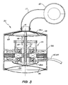
- Fig. 3 is a schematic cross sectional side view of a third embodiment of a fluid pressure generating means according to the invention, in the form of pump 80.
- the pump 80 is shown connected to an aortic compression means or blood pumping means in the form of cuff 82.
- the pump 80 is similar to the pump 60 described in relation to Fig. 2 and like reference numerals will be used to indicate like features. Differences between the pumps 60 and 80 are described in detail below.
- the pump 80 has a first external substantially rigid cylindrical housing portion 84, a pair of second internal substantially rigid housing portions 86a and 86b and a third substantially flexible housing portion 88. The latter seals an end of the first housing portion 84.
- the pump 80 also includes a second flexible housing portion 90 which seals the other end of the second housing portion 84 and forms a compliance chamber 92.
- the second housing portion 86 and the third flexible housing portion 88 abut, but are not connected, to each other.
- the operation of the pump 80 is similar to that described with reference to pump 60 in that the motor 20 is energised to reciprocally drive the threaded shaft 34 and thus the second housing portion 86a in directions 46 and 48 parallel to the longitudinal axis of the threaded shaft 34.
- Fig. 3 shows the pump 80 in a position after movement of the second housing portion 86a in the direction 46 and driving fluid from the second interior volume 68 into the cuff 82 to inflate same.
- the second membrane of 64 is drawn into the interior of the second housing portion 84 to maintain the interior volume 18 constant.
- Driving the threaded shaft 34 in the opposite direction 48 results in the housing portion 86b forcing the membrane 64 to the position shown in phantom which is external the second housing portion 84.
- This also results in the third housing portion 88 being drawn to the position also shown in phantom to maintain the interior volume 18 constant.
- fluid is drawn into the second interior volume 68 from the cuff 82 to deflate same.
- Figs. 4A to 4C show a fourth embodiment of a fluid pressure generating means according to the invention, in the form of pump 100.
- the pump 100 is similar to the pump 10 shown in Fig. 1 and like components have been referred to with like reference numerals.
- the pump 100 has been designed to be as thin as possible (dimensions: 82 mm long; 60 mm wide; and 45 mm deep) in order to allow positioning in a patient's chest in contact with the mediastinum adjacent the heart.
- the pump 100 is placed with the planar housing portion 14 lying in a sagittal plane and with the edge of the housing 100 clear of the inside surface of the chest wall. This orientation is chosen so as to minimise pain and trauma to the patient and also minimise the length of conduit required between the pump 100 and the aortic compression means (not shown). This positioning also assists the surgeon in placing the device.
- FIG. 5 to 7 there is shown a schematic longitudinal sectional view of a fifth embodiment of a fluid pressure generating means according to the invention in the form of pump 120.
- the pump 120 is shown connected to an aortic compression means or blood pumping means in the form of cuff 122.
- the construction and operation of the pump 120 is similar to the pump 10 shown in Fig. 1 and like features are indicated with like reference numerals.
- the size of the pump 120 is similar to the pump 100 shown in Figs. 4A to 4C , except it is more ovate and has flattened sides (See Fig. 6 ).
- Fig. 7 shows an external battery pack 123 which powers the pump 120.
- the flexible third housing portion 16 is sealingly connected about its outer edge 16b to the substantially rigid ovate cup-shaped first housing portion 12. The connection and sealing is achieved by a sealing rim 124 on the third portion 16 being snugly received in an annular recess 126 on the first portion 12.
- the substantially rigid flat ovate second housing portion 14 is received within a corresponding recess in the third portion 16, on the interior side of the third portion 16, and is thus within the interior volume 18.
- Fig. 5 shows the pump 120 in a position after movement of the second housing portion 14 in the direction 46, which draws fluid into the interior volume 18 from the cuff 122 and deflates same.
- Driving the threaded shaft 34 in the opposite direction 48 forces the second housing portion 14 towards the motor 20 (see the position of the shaft 34 shown in phantom). As previously described, when this occurs, fluid is forced from the interior volume 18 into the cuff 82 to inflate same.
- An advantage of the preferred embodiments of fluid pressure generating means described above is the liquid surrounding the motor is used both as a driving fluid to inflate/deflate the compressions (either directly as per the embodiments of Figs. 1 and 4 or indirectly as per the embodiment of Figs. 2 and 3 ) and as a cooling/lubricating/heat exchanging fluid.
- the liquid also dampens sound made by the pump mechanism. This simplifies the construction, and minimises the size, of the fluid pressure generating means.
- the motor Whilst the fluid pressure generating means will normally actively drive both the inflation and deflation of the aortic compression means, the motor is preferably designed so that the cogging torque of the motor is sufficiently low that the natural systolic blood pressure of the patient is sufficient to deflate the cuff. If the motor is inactivated for any reason with the cuff in an inflated condition (and thus with the aorta partially occluded), this arrangement means that the natural systolic blood pressure will deflate the cuff by pushing fluid from the cuff into the housing and passively driving the second housing portion away from the motor.
Abstract
Description
- The present invention relates to a fluid pressure generating means for use with a heart assist device.
- The applicant's international PCT patent application no.
PCT/AU00/00654 WO 00/76288 - It is a first object of the present invention to provide improved fluid pressure generating means suitable for use with the aortic compression means described in the PCT application. It is a second object to provide a fluid pressure generating means which may be placed more conveniently into the body of a patient.
-
US5300111 A discloses an implantable artificial heart having two ventricles. Blood is pumped alternately from each ventricle using a linear electric motor. -
EP0601804 A1 discloses an artificial heart wherein turning a roller screw causes a shaft to move back and forth, moving a pusher plate. Motion of the pusher plate simultaneously draws blood into a first pump space, and pushes blood out of a second pump space. -
US 4822357 discloses an auxiliary artificial heart comprising a pump having a single opening connected to the aorta and operable in synchronism with the heart in order to assist the normal functioning of the heart. -
US 4277706 discloses a heart pump consisting of a housing having an inlet and an outlet and a diaphragm adapted to be reciprocated to cause flow of flood through the inlet and the outlet, a brushless de motor mounted on the housing, the motor having a fixed ball screw nut and a ball screw mounted for axial movement with respect to the motor rotor while being fixed against rotation with respect to the rotor whereby rotation of the rotor causes the screw to move axially with respect to the motor thereby actuating the pump diaphragm. - Accordingly, in a first aspect, the present invention provides a fluid pressure generating means for a heart assist device having blood pumping means, according to claim 1.
- In another preferred form, the third housing portion is connected to only one of the first and second housing portions and abuts against the other of the first and second housing portions.
- The blood pumping means is preferably adapted to displace blood in the aorta, more specifically the ascending aorta, and preferably by compressing or deforming the aorta of a patient in counter-pulsation with the patient's heart. More preferably, the blood pumping means is adapted to displace blood from the ascending aorta of the patient. In an alternative arrangement, the fluid pressure generating means can be used to drive a conventional left ventricular assist device or an extra-ventricular co-pulsation heart compression device. In such an arrangement suitable valves are used to ensure the correct direction of blood flow through a pumping chamber driven by the fluid pressure generating means.
- In a further preferred form, one of the first and second housing portions is adapted to interface with the lung of a patient.
- The actuating means desirably includes a nut coupled to one of the first and second housing portions and a threaded shaft coupled to the other of the first and second housing portions, the threaded shaft and the nut being threadedly engaged and the motor being adapted to rotate the nut relative to the threaded shaft. In one arrangement, the nut is connected to the moveable one of the first and second housing portions and the threaded shaft is connected to the fixed one of the first and second housing portions. In another arrangement, the threaded shaft is connected to the moveable one of the first and second housing portions and the nut is connected to the fixed one of the first and second housing portions.
- In an embodiment, the outflow of the fluid from the inlet/outlet port is axial to the housing. In another embodiment, the outflow of the fluid from the inlet/outlet port is radial to the housing. In a further embodiment, the outflow of the fluid from the inlet/outlet port is tangential to the housing.
- A surface of the device is preferably curved to fit snugly with the chest wall and/or mediastinum and/or diaphragm of a patient.
- The blood pumping means is preferably in the form of a fluid operated cuff adapted to surround the patient's aorta.
- The fluid filling the housing is preferably a liquid. The liquid is preferably an oil or saline. The oil is preferably a silicone oil and desirably has viscosity between 10 and 100 centistokes, most desirably between 10 and 30 centistokes.
- In an unclaimed aspect, the present invention discloses a heart assist device including:
- a blood pumping means adapted, when actuated, to cause or assist the movement of blood around the patient's vasculature;
- a fluid reservoir;
- a fluid pressure generating means adapted to pump fluid from the fluid reservoir to the blood pumping means; and
- a housing containing both the fluid reservoir and the fluid pressure generating means that is so shaped and dimensioned as to be adapted to lie in the plueral cavity, adjacent to the lung, when the blood pumping means is functionally positioned within the patient.
- In another unclaimed aspect, the present invention discloses a method for the treatment of congestive heart failure, myocardial ischemia and like conditions, the method comprising:
- inserting into the plueral cavity within the chest (preferably the right chest) of a patient, and adjacent to the lung, a housing containing a fluid reservoir and a fluid pressure generating means adapted to pump fluid from the fluid reservoir to blood pumping means functionally placed in the patient so as to cause or assist the movement of blood around the patient's vasculature.
- Until now most implanted heart assist devices have been placed in the abdominal cavity of a patient. This is disadvantageous as it complicates the surgical procedure and is unduly invasive for the patient. The few proposals for placement of such a device in the chest cavity have proposed the placement of the device against the inside of the chest wall so that the device can be wired to the ribs of the patient. It was apparently felt that this was necessary to support the weight of the device and to prevent it from moving around in the patient. The present inventors have found that the device may be placed against the mediastinum directly adjacent the patient's heart and attached to surrounding soft tissue. The device will thus lie in the plueral cavity, adjacent to the lung. The device preferably lies in a sagittal plane within the patient's body. Desirably, the device will not touch the inside surface of the chest wall at all. This placement will reduce pain for the patient and make placement of the device easier for the surgeon implanting the device.
- Preferably, the blood pumping means referred to in the above method is adapted to compress the aorta of a patient in counter-pulsation with the patient's heart. More preferably, the blood pumping means is adapted to compress the ascending aorta of the patient.
- In a fourth aspect, the present invention provides a heart assist device including:
- a blood pumping means adapted, when actuated, to cause or assist the movement of blood around the patient's vasculature;
- a fluid reservoir; and
- a fluid pressure generating means driven by an electric motor and adapted to pump a liquid from the fluid reservoir to the blood pumping means;
- the electric motor having a cogging torque which is sufficiently low that the natural systolic blood pressure of the patient is sufficient to cause liquid in the blood pumping means to be returned to the fluid reservoir in the event that the electric motor stops.
- Preferred embodiments of the invention will now be described, by way of examples only, with reference to the accompanying drawings in which:
-
Fig. 1 is a schematic longitudinal sectional view of a first embodiment of a fluid pressure generating means according to the invention; -
Fig. 2 is a schematic longitudinal sectional view of a second embodiment of a fluid pressure generating means according to the invention; -
Fig. 3 is a schematic longitudinal sectional view of a third embodiment of a fluid pressure generating means according to the invention connected to a heart assist device; -
Fig. 4a is a perspective view of a fourth embodiment of a fluid pressure generating means according to the invention; -
Fig. 4b is an underside perspective view of a housing portion of the fluid pressure generating means shown inFig. 4a ; -
Fig. 4c is a schematic longitudinal sectional view of the fluid pressure generating means shown inFig. 4a ; and -
Fig. 5 is a schematic longitudinal sectional view of a fifth embodiment of a heart assist device according to the invention; -
Fig. 6 is a perspective view of the device shown inFig. 5 ; and -
Fig. 7 is a perspective view of the device shown inFig. 6 after implantation into the pleural cavity, medial to the lung, of a patient. - Referring firstly to
Fig. 1 , there is shown a schematic longitudinal sectional view of a first embodiment of a fluid pressure generating means according to the invention, in the form ofpump 10. Thepump 10 includes a housing, indicated generally by thereference numeral 11, comprising a substantially rigid bell-shapedfirst housing portion 12, a substantially rigid flat circularsecond housing portion 14 and a flexible third housing portion ormembrane 16. - The first, second and
third housing portions housing 11 around an interior volume denoted 18, which is filled with a silicone oil. Thesecond housing portion 12 is itself formed from a cone-shapedportion 12a which is sealingly connected, after assembly of thepump 10, to acylindrical portion 12b. - The cone-shaped
portion 12a also includes an inlet/outlet port 15, which is connected in fluid communication with an aortic compression means or blood pumping means (not shown) by aconduit 17. - The
membrane 16 is substantially annular in configuration and has enlarged inner andouter edges circumferential recesses second housing portions - The
pump 10 also includes an electric motor, indicated generally by thereference numeral 20, within theinterior volume 18 of thehousing 11. The motor includes arotor 21,rotor laminations 22,magnets 24,stator 25,stator laminations 26,end windings 28 andbearings 30. - The
stator 25 is fixed to thehousing portion 12a by a number of screws 30 (only one shown). Therotor 21 is fixed to anut 32, which is itself threadedly engaged with a threadedshaft 34 through ball bearings (not shown). Theshaft 34 is fixed to thehousing portion 14 byscrew 36. Thestator 25 also includes a number of guide journals 38 (only one shown) through which are guided a corresponding number ofshafts 40 that depend from thehousing portion 14. - Power and control signals are fed to the
motor 20 throughlines - The operation of the
pump 10 will now be described. Energising themotor 20 to rotate in a first direction rotates thenut 32 relative to the threadedshaft 34 which causes the threadedshaft 34 to move in a direction parallel to its longitudinal axis in a first direction indicated byarrow 46.Fig. 1 shows theshaft 34 at the end of its travel in this direction and after driving thehousing portion 14 away from thehousing portion 12 to increase theinterior volume 18 and cause a suction or negative pressure at the inlet/outlet port 15. This suction actively deflates the aortic compression means (not shown). - Energising the motor to rotate in the opposite direction causes the threaded
shaft 34 to move parallel to the longitudinal axis in the opposite direction indicated byarrow 48 and draw theportion 14 towards thehousing portion 12. The end limit of travel in this direction is indicated in phantom inFig. 1 and, with reference to which it should be noted that, theguide shaft 40 abuts the inner surface of thehousing portion 12a at the limit of its travel atrecess 50. Drawing theflexible portion 14 towards thehousing portion 12 reduces theinterior volume 18 which causes a positive pressure at the inlet/outlet port 15 and drives fluid from theinterior volume 18 to inflate the aortic compression means. - The
motor 20 is actuated cyclicly in this manner in counterpulsation with the patient's heart in response to signals received from an ECG monitor or systemic arterial pressure, as disclosed in the PCT application. - Referring now to
Fig. 2 , there is shown a schematic longitudinal sectional view of a second embodiment of a fluid pressure generating means according to the invention, in the form of pump 60. The pump 60 is similar to thepump 10 shown inFig.1 and like features are indicated with like reference numerals. Differences between thepumps 10 and 60 are described in detail below. - Firstly, the
housing portion 12a of the pump 60 includes anopening 62 sealed by a secondflexible membrane 64 which forms acompliance chamber 65. Thechamber 65 is in fluid communication with theinterior volume 18. Secondly, the inlet/outlet port 15 is provided in afurther housing portion 66 which is sealed with respect to the side of thesecond housing portions 14 andthird housing portion 16 that is remote themotor 20. Thehousing portion 66 creates, in conjunction with thehousing portions interior volume 68 in fluid communication with the aortic compression means or blood pumping means (not shown) viaconduit 17. - The operation of the pump 60 is similar to that as described with reference to the
pump 10 with the exception that the movement of thehousing portion 14 causes volume changes in the secondinterior volume 68 which in turn inflates and deflates the aortic compression means. The movement of thehousing portion 14 also causes fluid movement in the part of theinterior volume 18 within the first, second andthird housing portions compliance chamber 65, which is shown having a decreased volume in response to the compression means being inflated. Thechamber 65 will have an increased volume in response to the compression means being deflated, as is shown in phantom. - As the
interior volumes third housing portions interior volumes 18 and 60, as desired. For example, a saline solution can be used in theinterior volume 68 and a lubricating oil can be used in theinterior volume 18 which contains themotor 20. -
Fig. 3 is a schematic cross sectional side view of a third embodiment of a fluid pressure generating means according to the invention, in the form ofpump 80. Thepump 80 is shown connected to an aortic compression means or blood pumping means in the form ofcuff 82. Thepump 80 is similar to the pump 60 described in relation toFig. 2 and like reference numerals will be used to indicate like features. Differences between thepumps 60 and 80 are described in detail below. - Firstly, the
pump 80 has a first external substantially rigid cylindrical housing portion 84, a pair of second internal substantially rigid housing portions 86a and 86b and a third substantiallyflexible housing portion 88. The latter seals an end of the first housing portion 84. Thepump 80 also includes a secondflexible housing portion 90 which seals the other end of the second housing portion 84 and forms acompliance chamber 92. Secondly, the second housing portion 86 and the thirdflexible housing portion 88 abut, but are not connected, to each other. - The operation of the
pump 80 is similar to that described with reference to pump 60 in that themotor 20 is energised to reciprocally drive the threadedshaft 34 and thus the second housing portion 86a indirections shaft 34. -
Fig. 3 shows thepump 80 in a position after movement of the second housing portion 86a in thedirection 46 and driving fluid from the secondinterior volume 68 into thecuff 82 to inflate same. In this position, the second membrane of 64 is drawn into the interior of the second housing portion 84 to maintain theinterior volume 18 constant. Driving the threadedshaft 34 in theopposite direction 48 results in the housing portion 86b forcing themembrane 64 to the position shown in phantom which is external the second housing portion 84. This also results in thethird housing portion 88 being drawn to the position also shown in phantom to maintain theinterior volume 18 constant. As previously described in relation to pump 60, when the third housing portion 86 is in this position fluid is drawn into the secondinterior volume 68 from thecuff 82 to deflate same. -
Figs. 4A to 4C show a fourth embodiment of a fluid pressure generating means according to the invention, in the form ofpump 100. Thepump 100 is similar to thepump 10 shown inFig. 1 and like components have been referred to with like reference numerals. However, thepump 100 has been designed to be as thin as possible (dimensions: 82 mm long; 60 mm wide; and 45 mm deep) in order to allow positioning in a patient's chest in contact with the mediastinum adjacent the heart. Thepump 100 is placed with theplanar housing portion 14 lying in a sagittal plane and with the edge of thehousing 100 clear of the inside surface of the chest wall. This orientation is chosen so as to minimise pain and trauma to the patient and also minimise the length of conduit required between thepump 100 and the aortic compression means (not shown). This positioning also assists the surgeon in placing the device. - Referring finally to
Figs. 5 to 7 , there is shown a schematic longitudinal sectional view of a fifth embodiment of a fluid pressure generating means according to the invention in the form ofpump 120. Thepump 120 is shown connected to an aortic compression means or blood pumping means in the form ofcuff 122. The construction and operation of thepump 120 is similar to thepump 10 shown inFig. 1 and like features are indicated with like reference numerals. The size of thepump 120 is similar to thepump 100 shown inFigs. 4A to 4C , except it is more ovate and has flattened sides (SeeFig. 6 ). The ovate form of thepump 120 and the positioning of thecuff 122 nearer one end allows the device to be placed in the plural cavity, medial to the lung, and lying in a sagittal plane within the patient's body, as is shown inFig. 7 . Thepump 120 does not touch the inside surface of the patient's chest wall in this position.Fig. 7 also shows anexternal battery pack 123 which powers thepump 120. - The main differences between the
pumps third housing portion 16 is sealingly connected about itsouter edge 16b to the substantially rigid ovate cup-shapedfirst housing portion 12. The connection and sealing is achieved by a sealingrim 124 on thethird portion 16 being snugly received in anannular recess 126 on thefirst portion 12. Secondly, the substantially rigid flat ovatesecond housing portion 14 is received within a corresponding recess in thethird portion 16, on the interior side of thethird portion 16, and is thus within theinterior volume 18. -
Fig. 5 shows thepump 120 in a position after movement of thesecond housing portion 14 in thedirection 46, which draws fluid into theinterior volume 18 from thecuff 122 and deflates same. Driving the threadedshaft 34 in theopposite direction 48 forces thesecond housing portion 14 towards the motor 20 (see the position of theshaft 34 shown in phantom). As previously described, when this occurs, fluid is forced from theinterior volume 18 into thecuff 82 to inflate same. - An advantage of the preferred embodiments of fluid pressure generating means described above is the liquid surrounding the motor is used both as a driving fluid to inflate/deflate the compressions (either directly as per the embodiments of
Figs. 1 and4 or indirectly as per the embodiment ofFigs. 2 and3 ) and as a cooling/lubricating/heat exchanging fluid. The liquid also dampens sound made by the pump mechanism. This simplifies the construction, and minimises the size, of the fluid pressure generating means. - Whilst the fluid pressure generating means will normally actively drive both the inflation and deflation of the aortic compression means, the motor is preferably designed so that the cogging torque of the motor is sufficiently low that the natural systolic blood pressure of the patient is sufficient to deflate the cuff. If the motor is inactivated for any reason with the cuff in an inflated condition (and thus with the aorta partially occluded), this arrangement means that the natural systolic blood pressure will deflate the cuff by pushing fluid from the cuff into the housing and passively driving the second housing portion away from the motor.
- It will be appreciated by person skilled in the art that numerous variations and/or modifications can be made to the invention as shown in the specific embodiments without departing from the scope of invention as claimed. For example, the embodiments of the invention are not restricted for use with the embodiments of the heart assist device shown in the PCT application. The specific embodiments are, therefore, to be considered in all respects as illustrative and not restrictive.
Claims (18)
- A fluid pressure generating device (10) for a heart assist device having a blood pumping means, the fluid pressure generating device (10) including:a housing (11) defining an interior volume (18), and having a substantially rigid first housing portion (12), a substantially rigid second housing portion (14), a flexible third housing portion (16) extending between the first (12) and second (14) housing portions and an inlet/outlet port (15) connected to one of said housings and adapted for fluid communication with the blood pumping means, the third housing (16) having an outer surface about its periphery, an inner surface facing into the interior (18) of the housing (11) and is joined along an edge (16b) to the first housing portion (12); anda fluid filling the interior volume (18) of the housing (11);characterised in that a motor (20) is disposed within the interior volume (18) of the housing (11) and connected between the first (12) and second (14) housing portions, actuation of the motor (20) moving the first (12) and second (14) housing portions relative to one another to generate fluid pressure changes at the inlet/outlet port (15), wherein one (14) of the first (12) and second (14) housing portions is moveable and the other (12) of the first (12) and second (14) housing portions is fixed, the moveable housing portion (14) being exposed to the outside of the heart assist device.
- The fluid pressure generating device (10) as claimed in claim 1, wherein the blood pumping means is adapted to displace blood from the aorta of a patient in counter-pulsation with the patient's heart.
- The fluid pressure generating device (10) as claimed in claim 1, wherein the blood pumping means is adapted to displace blood from the ascending aorta of the patient.
- The fluid pressure generating device (10) as claimed in claim 1, wherein the fluid pressure generating device is adapted to drive a conventional left ventricular assist device or an extra-ventricular co-pulsation heart compression device.
- The fluid pressure generating device (10) as claimed in claim 1, wherein the moveable housing portion (14) is adapted to interface with the lung of a patient.
- The fluid pressure generating device as claimed in claim 1, wherein the actuating means includes a nut (32) coupled to one (14) of the first (12) and second (14) housing portions and a threaded shaft (34) coupled to the other (12) of the first (12) and second (14) housing portions, the threaded shaft (34) and the nut (32) being threadedly engaged and the motor (20) being adapted to rotate the nut (32) relative to the threaded shaft (34).
- The fluid pressure generating device as claimed in claim 6, wherein the nut (32) is connected to the moveable one (14) of the first (12)and second (14) housing portions and the threaded shaft (34) is connected to the fixed one (12) of the first (12) and second (14) housing portions.
- The fluid pressure generating device as claimed in claim 6, wherein the threaded shaft (34) is connected to the moveable one (14) of the first (12) and second (14) housing portions and the nut (32) is connected to the fixed one (12) of the first (12) and second (14) housing portions.
- The fluid pressure generating device as claimed in claim 1, wherein the outflow of the fluid from the inlet/outlet port (15) is axial to the housing (18).
- The fluid pressure generating device as claimed in claim 1, wherein the outflow of the fluid from the inlet/outlet port (15) is radial to the housing (18).
- The fluid pressure generating device as claimed in claim 1, wherein the outflow of the fluid from the inlet/outlet port (15) is tangential to the housing (18).
- The fluid pressure generating device as claimed in claim 1, wherein a surface of the device (10) is curved to fit snugly with the chest wall or mediastinum of a patient.
- The fluid pressure generating device (10) as claimed in claim 1, wherein the aortic compression means is in the form of a fluid operated cuff (82) adapted to surround the patient's aorta.
- The fluid pressure generating device (10) as claimed in claim 1, wherein the fluid filling the housing is a liquid.
- The fluid pressure generating device (10) as claimed in claim 14, wherein the liquid is an oil or saline.
- The fluid pressure generating device (10) as claimed in claim 15, wherein the oil is silicone oil.
- The fluid pressure generating device (10) as claimed in claim 16, wherein the oil has a viscosity between 10 and 100 centistokcs.
- The fluid pressure generating device (10) as claimed in claim 17, wherein the oil has a viscosity between 10 and 30 centistokes.
Applications Claiming Priority (3)
| Application Number | Priority Date | Filing Date | Title |
|---|---|---|---|
| AUPR6690A AUPR669001A0 (en) | 2001-07-30 | 2001-07-30 | A fluid pressure generating means |
| AUPR669001 | 2001-07-30 | ||
| PCT/AU2002/000974 WO2003011365A1 (en) | 2001-07-30 | 2002-07-22 | A fluid pressure generating means |
Publications (3)
| Publication Number | Publication Date |
|---|---|
| EP1418959A1 EP1418959A1 (en) | 2004-05-19 |
| EP1418959A4 EP1418959A4 (en) | 2007-03-07 |
| EP1418959B1 true EP1418959B1 (en) | 2011-11-23 |
Family
ID=3830646
Family Applications (1)
| Application Number | Title | Priority Date | Filing Date |
|---|---|---|---|
| EP02748447A Expired - Lifetime EP1418959B1 (en) | 2001-07-30 | 2002-07-22 | A fluid pressure generating means |
Country Status (9)
| Country | Link |
|---|---|
| US (4) | US7306558B2 (en) |
| EP (1) | EP1418959B1 (en) |
| JP (1) | JP4201705B2 (en) |
| AT (1) | ATE534416T1 (en) |
| AU (1) | AUPR669001A0 (en) |
| CA (1) | CA2419809C (en) |
| DK (1) | DK1418959T3 (en) |
| ES (1) | ES2379728T3 (en) |
| WO (1) | WO2003011365A1 (en) |
Families Citing this family (29)
| Publication number | Priority date | Publication date | Assignee | Title |
|---|---|---|---|---|
| AUPQ090499A0 (en) | 1999-06-10 | 1999-07-01 | Peters, William S | Heart assist device and system |
| GB0023412D0 (en) | 2000-09-23 | 2000-11-08 | Khaghani Asghar | Aortic counterpulsator |
| US6589267B1 (en) * | 2000-11-10 | 2003-07-08 | Vasomedical, Inc. | High efficiency external counterpulsation apparatus and method for controlling same |
| AUPR669001A0 (en) * | 2001-07-30 | 2001-08-23 | Sunshine Heart Company Pty Ltd | A fluid pressure generating means |
| AU2002952691A0 (en) | 2002-11-15 | 2002-11-28 | Sunshine Heart Company Pty Ltd | Heart assist device utilising aortic deformation |
| US7862499B2 (en) | 2003-10-30 | 2011-01-04 | Sunshine Heart Company Pty Ltd | Blood vessel wrap |
| AU2004284842B2 (en) | 2003-10-31 | 2010-03-04 | Nuwellis, Inc. | Synchronisation control system |
| US7887478B2 (en) | 2003-10-31 | 2011-02-15 | Sunshine Heart Company Pty Ltd | Percutaneous gas-line |
| CN1878581B (en) | 2003-11-11 | 2010-07-07 | 阳光心脏有限公司 | Actuator for a heart assist device |
| PL1715902T3 (en) * | 2004-01-08 | 2017-01-31 | Sullivan, Paul Joseph | Nondestructive fluid transfer device |
| WO2005084730A1 (en) | 2004-03-02 | 2005-09-15 | Peter William Walsh | A vessel or sac wall treatment and a cardiac assist device |
| US7572217B1 (en) * | 2004-06-15 | 2009-08-11 | University Of Louisville Research Foundation, Inc. | System and method for providing cardiac support and promoting myocardial recovery |
| US20060052659A1 (en) * | 2004-09-07 | 2006-03-09 | Topaz Stephen R | Cardiac device and method |
| US20060058716A1 (en) * | 2004-09-14 | 2006-03-16 | Hui John C K | Unitary external counterpulsation device |
| EP2054103B1 (en) | 2006-08-21 | 2019-05-29 | Sunshine Heart Company Pty Ltd | An improved wrap for a heart assist device |
| US8140731B2 (en) * | 2007-08-27 | 2012-03-20 | International Business Machines Corporation | System for data processing using a multi-tiered full-graph interconnect architecture |
| US7958183B2 (en) * | 2007-08-27 | 2011-06-07 | International Business Machines Corporation | Performing collective operations using software setup and partial software execution at leaf nodes in a multi-tiered full-graph interconnect architecture |
| CN102939117B (en) | 2010-04-02 | 2015-12-02 | 阳光心脏有限公司 | Combination heart assist system, method and apparatus |
| WO2013082621A1 (en) | 2011-12-03 | 2013-06-06 | Indiana University Research And Technology Corporation | Cavopulmonary viscous impeller assist device and method |
| WO2013138451A1 (en) * | 2012-03-13 | 2013-09-19 | Sunshine Heart Company Pty Ltd | Methods, systems, and devices relating to wireless power transfer |
| JP2016508841A (en) * | 2013-03-05 | 2016-03-24 | サンシャイン・ハート・カンパニー・ピーティーワイ・リミテッド | Method, system and device for safety device pumps for medical devices |
| USD770947S1 (en) | 2015-01-28 | 2016-11-08 | Hni Technologies Inc. | Chair arm |
| USD784208S1 (en) | 2015-01-28 | 2017-04-18 | Hni Technologies Inc. | Chair |
| USD784210S1 (en) | 2015-01-28 | 2017-04-18 | Hni Technologies Inc. | Chair back |
| WO2017112695A1 (en) * | 2015-12-21 | 2017-06-29 | Heartware, Inc. | Implantable mechanical circulatory support devices |
| CN105709286B (en) * | 2016-01-18 | 2018-07-31 | 暨南大学 | With the matching used stepless regulation and control device in biventricular external auxiliary circulation blood pump room |
| US10583292B2 (en) | 2016-10-18 | 2020-03-10 | Chf Solutions, Inc. | Electronic neuromodulatory emulation of extra- and intra-aortic balloon pump counter-pulsation systems and methods |
| EP4127471A1 (en) | 2020-03-31 | 2023-02-08 | Graco Minnesota Inc. | Electrically operated displacement pump |
| US20220062055A1 (en) * | 2020-08-26 | 2022-03-03 | Nina D. Farzin | Device For Extracting Nasal Mucus Or Earwax |
Family Cites Families (120)
| Publication number | Priority date | Publication date | Assignee | Title |
|---|---|---|---|---|
| US283660A (en) | 1883-08-21 | Compression-cock | ||
| US929571A (en) | 1908-09-19 | 1909-07-27 | Dubied & Cie Sa E | Valve for pneumatic tires. |
| US1576397A (en) | 1925-07-18 | 1926-03-09 | Yanagi Tokujiro | Tourniquet |
| US1719316A (en) | 1927-03-25 | 1929-07-02 | Central Valve Mfg Co | Valve |
| DE1541311A1 (en) * | 1965-11-24 | 1969-09-11 | Zacouto Dr Med Fred | A device which can at least partially be implanted in the organisms to compensate for a heart failure in higher mammals |
| US3467077A (en) | 1966-06-30 | 1969-09-16 | Dupaco Inc | Sphygmomanometric cuff |
| US3597766A (en) * | 1968-07-11 | 1971-08-10 | Atomic Energy Commission | Artificial heart pumping system powered by a modified stirling cycle engine-compressor having a freely reciprocable displacer piston |
| US3552383A (en) | 1969-01-08 | 1971-01-05 | Ibm | Method and system for estimation of arterial pressure |
| US4014318A (en) | 1973-08-20 | 1977-03-29 | Dockum James M | Circulatory assist device and system |
| US4051840A (en) | 1976-01-05 | 1977-10-04 | Sinai Hospital Of Detroit | Dynamic aortic patch |
| US4195623A (en) | 1977-07-21 | 1980-04-01 | Phillips Steven J | Parallel aorta balloon pump and method of using same |
| US4176411A (en) | 1977-11-28 | 1979-12-04 | Runge Thomas M | Cardiac assist device employing electrically stimulated artificial muscle |
| US4236482A (en) | 1978-06-09 | 1980-12-02 | Champion International Corporation | Apparatus for applying sealing material to envelopes |
| US4277706A (en) * | 1979-04-16 | 1981-07-07 | Nu-Tech Industries, Inc. | Actuator for heart pump |
| US4304225A (en) | 1979-04-30 | 1981-12-08 | Lloyd And Associates | Control system for body organs |
| FR2458288A1 (en) * | 1979-06-11 | 1981-01-02 | Belenger Jacques | Cardiac pump with pulsed action - has microprocessor controlled stepping motor acting via screw mechanism on pump diaphragm |
| US4256094A (en) | 1979-06-18 | 1981-03-17 | Kapp John P | Arterial pressure control system |
| US4457673A (en) | 1980-11-28 | 1984-07-03 | Novacor Medical Corporation | Pump and actuator mechanism |
| FR2502499B1 (en) | 1981-03-27 | 1987-01-23 | Farcot Jean Christian | APPARATUS FOR BLOOD RETROPERFUSION, IN PARTICULAR FOR THE TREATMENT OF INFARCTUS BY INJECTION OF ARTERIAL BLOOD INTO THE CORONARY SINUS |
| US4428378A (en) | 1981-11-19 | 1984-01-31 | Medtronic, Inc. | Rate adaptive pacer |
| US4454891A (en) | 1982-03-09 | 1984-06-19 | Emerson Electric Co. (H & H Precision Products Division) | Air gap drain module for use in a reverse osmosis system |
| US4515587A (en) | 1983-02-14 | 1985-05-07 | Smec, Inc. | IAB having apparatus for assuring proper balloon inflation and deflation |
| US4771765A (en) | 1984-02-21 | 1988-09-20 | Choy Daniel S J | Heart assist device and method of use |
| US4630597A (en) | 1984-04-30 | 1986-12-23 | Adrian Kantrowitz | Dynamic aortic patch for thoracic or abdominal implantation |
| US4583523A (en) | 1984-07-02 | 1986-04-22 | Lloyd & Associates | Implantable heart assist device and method of implanting same |
| US4594731A (en) | 1984-11-09 | 1986-06-10 | University Of Utah | Electronic stethoscope |
| US4881939A (en) | 1985-02-19 | 1989-11-21 | The Johns Hopkins University | Implantable helical cuff |
| FR2577423B1 (en) | 1985-02-20 | 1989-05-05 | Gilles Karcher | CIRCULATORY AND CORONARY ASSISTANCE PUMP WITH INTRA-AORTIC BALLOONS |
| DE3506791A1 (en) | 1985-02-22 | 1986-08-28 | Biotronik Meß- und Therapiegeräte GmbH & Co Ingenieurbüro Berlin, 1000 Berlin | HEART PACEMAKER WITH PHYSIOLOGICAL CONTROL |
| US4813952A (en) | 1985-08-01 | 1989-03-21 | Medtronic, Inc. | Cardiac assist device |
| DE3677862D1 (en) | 1985-08-01 | 1991-04-11 | Medtronic Inc | DEVICE FOR SUPPORT. |
| DE3535504A1 (en) | 1985-10-04 | 1987-04-09 | Siemens Ag | HEART PACEMAKER |
| US4676482A (en) | 1986-04-28 | 1987-06-30 | Rexnord Inc. | Valve seat insert |
| SE454942B (en) | 1986-05-22 | 1988-06-13 | Astra Tech Ab | HEART HELP DEVICE FOR INOPERATION IN BROSTHALAN |
| US4979936A (en) | 1987-04-28 | 1990-12-25 | Trustees Of The University Of Pennsylvania | Autologous biologic pump motor |
| US4822357A (en) * | 1987-04-29 | 1989-04-18 | Articor Limited | Auxiliary artificial heart |
| DE3714923A1 (en) * | 1987-05-05 | 1988-12-01 | Waeschle Maschf Gmbh | DEVICE FOR PNEUMATICALLY CONVEYING SCHUETTGUT |
| US4809676A (en) | 1987-12-28 | 1989-03-07 | Freeman Maynard L | Heart assist device and method of implanting it |
| JPH02297381A (en) | 1988-10-05 | 1990-12-07 | Abiomed Lp | Cardiac function aid air-bladder and inserting method therefor |
| US5069662A (en) | 1988-10-21 | 1991-12-03 | Delcath Systems, Inc. | Cancer treatment |
| US5089017A (en) | 1989-01-17 | 1992-02-18 | Young David B | Drive system for artificial hearts and left-ventricular assist devices |
| FR2645739A1 (en) | 1989-04-14 | 1990-10-19 | Vm Tech Sa | Cardiac assistance device and its use |
| EP0923954A3 (en) | 1989-06-20 | 1999-08-11 | Btg International Limited | Improving blood flow |
| US5267940A (en) | 1989-11-29 | 1993-12-07 | The Administrators Of The Tulane Educational Fund | Cardiovascular flow enhancer and method of operation |
| US5477864A (en) | 1989-12-21 | 1995-12-26 | Smith & Nephew Richards, Inc. | Cardiovascular guidewire of enhanced biocompatibility |
| ES2020787A6 (en) | 1990-07-20 | 1991-09-16 | Figuera Aymerich Diego | Intra-ventricular expansible assist pump |
| RU1767723C (en) | 1990-08-14 | 1995-01-27 | Кирово-Чепецкий химический комбинат | Artificial heart valve |
| CA2052310A1 (en) | 1990-10-09 | 1992-04-10 | Thomas L. Foster | Surgical access sheath |
| US5205810A (en) | 1990-10-15 | 1993-04-27 | Medtronic, Inc. | Muscle powered cardiac assist system |
| US5429584A (en) | 1990-11-09 | 1995-07-04 | Mcgill University | Cardiac assist method and apparatus |
| US5222980A (en) | 1991-09-27 | 1993-06-29 | Medtronic, Inc. | Implantable heart-assist device |
| US5344385A (en) * | 1991-09-30 | 1994-09-06 | Thoratec Laboratories Corporation | Step-down skeletal muscle energy conversion system |
| US5360445A (en) * | 1991-11-06 | 1994-11-01 | International Business Machines Corporation | Blood pump actuator |
| US5273518A (en) | 1992-01-31 | 1993-12-28 | Medtronic, Inc. | Cardiac assist apparatus |
| US5300111A (en) * | 1992-02-03 | 1994-04-05 | Pyxis, Inc. | Total artificial heart |
| US5814012A (en) | 1992-03-16 | 1998-09-29 | Birtcher Medical Systems, Inc. | Method and apparatus for relieving excess insufflation pressure |
| BR9305486A (en) | 1992-04-17 | 1994-10-11 | Yoshiharu Kiyota | Internal cardiac assist device |
| US5337752A (en) | 1992-05-21 | 1994-08-16 | Mcg International, Inc. | System for simultaneously producing and synchronizing spectral patterns of heart sounds and an ECG signal |
| US5676651A (en) | 1992-08-06 | 1997-10-14 | Electric Boat Corporation | Surgically implantable pump arrangement and method for pumping body fluids |
| EP0615722B1 (en) | 1993-03-15 | 1998-06-10 | Omron Corporation | Cuff for blood pressure meter |
| EP0673229A4 (en) | 1993-08-25 | 1996-09-11 | Life Surgery Inc | Surgical ligation clip. |
| JP3619520B2 (en) | 1993-09-10 | 2005-02-09 | オタワ ハート インスティテュート リサーチ コーポレイション | Electro-hydraulic ventricular assist device |
| US6045496A (en) | 1994-04-15 | 2000-04-04 | Allegheny-Singer Research Institute | Occluder device and method of making |
| US5843170A (en) | 1994-09-02 | 1998-12-01 | Ahn; Sam Seunghae | Apparatus and method for performing aneurysm repair |
| US5607378A (en) | 1994-11-21 | 1997-03-04 | Winston; Edith | Method of exercising a selected muscle |
| US5823997A (en) * | 1995-01-10 | 1998-10-20 | Specialized Health Products, Inc. | Medical needle safety apparatus and methods |
| US5554177A (en) | 1995-03-27 | 1996-09-10 | Medtronic, Inc. | Method and apparatus to optimize pacing based on intensity of acoustic signal |
| US5647380A (en) | 1995-06-07 | 1997-07-15 | W. L. Gore & Associates, Inc. | Method of making a left ventricular assist device |
| FR2744924B1 (en) * | 1996-02-21 | 1998-04-24 | Franchi Pierre | PRESSURE GENERATOR / REGULATOR DEVICE FOR AN IMPLANTABLE HEART ASSISTANCE PUMP OF THE COUNTERPRESSURE BALLOON TYPE |
| WO1997040755A1 (en) | 1996-04-29 | 1997-11-06 | W.L. Gore & Associates, Inc. | Device for restoring competence to venous valves |
| US6059750A (en) | 1996-08-01 | 2000-05-09 | Thomas J. Fogarty | Minimally invasive direct cardiac massage device and method |
| US5820542A (en) | 1996-10-31 | 1998-10-13 | Momentum Medical, Inc. | Modified circulatory assist device |
| US5827171A (en) | 1996-10-31 | 1998-10-27 | Momentum Medical, Inc. | Intravascular circulatory assist device |
| US5792195A (en) | 1996-12-16 | 1998-08-11 | Cardiac Pacemakers, Inc. | Acceleration sensed safe upper rate envelope for calculating the hemodynamic upper rate limit for a rate adaptive cardiac rhythm management device |
| JPH10328297A (en) * | 1997-06-02 | 1998-12-15 | Buaayu:Kk | Heart function assisting device |
| FR2766373B1 (en) * | 1997-07-24 | 1999-08-27 | Commissariat Energie Atomique | VENTRICULAR COUNTER-PULSE HEART ASSISTANCE DEVICE |
| US5975140A (en) | 1997-07-28 | 1999-11-02 | Lin; Ching-Yi | Gooseneck faucet |
| FR2767874A1 (en) * | 1997-08-26 | 1999-02-26 | Commissariat Energie Atomique | Fluid actuator for implantable cardiac assist operating in counter pulse mode. |
| AU741646B2 (en) | 1997-09-30 | 2001-12-06 | L. Vad Technology, Inc. | Cardiovascular support control system |
| US5980448A (en) | 1998-01-28 | 1999-11-09 | Vascor, Inc. | Single chamber blood pump |
| JP4051812B2 (en) | 1998-04-13 | 2008-02-27 | 株式会社ジェイ・エム・エス | Extracorporeal circulation device with control function |
| US6251061B1 (en) | 1998-09-09 | 2001-06-26 | Scimed Life Systems, Inc. | Cardiac assist device using field controlled fluid |
| US6132636A (en) | 1998-10-23 | 2000-10-17 | Allied Signal Inc | Leak-detecting refrigerant compositions containing oxazolyl-coumarin dyes |
| US6432039B1 (en) | 1998-12-21 | 2002-08-13 | Corset, Inc. | Methods and apparatus for reinforcement of the heart ventricles |
| US6226843B1 (en) | 1999-02-25 | 2001-05-08 | Design Standards Corporation | Ligating clip |
| US6210318B1 (en) | 1999-03-09 | 2001-04-03 | Abiomed, Inc. | Stented balloon pump system and method for using same |
| US20010016676A1 (en) | 1999-04-21 | 2001-08-23 | Jonathan Williams | Intra-aortic balloon pump condensation prevention system |
| US6210319B1 (en) | 1999-04-21 | 2001-04-03 | Datascope Investment Corp. | Intra-aortic balloon pump condensation prevention system |
| AUPQ090499A0 (en) | 1999-06-10 | 1999-07-01 | Peters, William S | Heart assist device and system |
| US6553263B1 (en) | 1999-07-30 | 2003-04-22 | Advanced Bionics Corporation | Implantable pulse generators using rechargeable zero-volt technology lithium-ion batteries |
| US6471633B1 (en) | 1999-08-23 | 2002-10-29 | L.Vad Technology, Inc. | Mechanical auxillary ventricle blood pump with reduced waist portion |
| US6585635B1 (en) | 1999-09-17 | 2003-07-01 | Core Medical, Inc. | Method and system for pericardial modification |
| US6406422B1 (en) | 2000-03-02 | 2002-06-18 | Levram Medical Devices, Ltd. | Ventricular-assist method and apparatus |
| US6643548B1 (en) | 2000-04-06 | 2003-11-04 | Pacesetter, Inc. | Implantable cardiac stimulation device for monitoring heart sounds to detect progression and regression of heart disease and method thereof |
| US6572534B1 (en) | 2000-09-14 | 2003-06-03 | Abiomed, Inc. | System and method for implanting a cardiac wrap |
| AUPR031200A0 (en) | 2000-09-22 | 2000-10-12 | Sunshine Heart Company Pty Ltd | Heart assist devices, systems and methods II |
| GB0023412D0 (en) | 2000-09-23 | 2000-11-08 | Khaghani Asghar | Aortic counterpulsator |
| US6808483B1 (en) | 2000-10-03 | 2004-10-26 | Paul A. Spence | Implantable heart assist devices and methods |
| NL1016320C2 (en) | 2000-10-03 | 2002-04-04 | Jozef Reinier Cornelis Jansen | Device for controlling heart supporting devices. |
| US6616596B1 (en) | 2000-11-28 | 2003-09-09 | Abiomed, Inc. | Cardiac assistance systems having multiple layers of inflatable elements |
| US6626821B1 (en) | 2001-05-22 | 2003-09-30 | Abiomed, Inc. | Flow-balanced cardiac wrap |
| AUPR669001A0 (en) * | 2001-07-30 | 2001-08-23 | Sunshine Heart Company Pty Ltd | A fluid pressure generating means |
| JP3862999B2 (en) | 2001-11-06 | 2006-12-27 | 株式会社ミワテック | Transcutaneous information transmission system for implantable artificial heart. |
| US6810287B2 (en) | 2001-12-03 | 2004-10-26 | Cardiac Pacemakers, Inc. | Implantable cardiac disease management device with trigger-stored polysomnogram and phonocardiogram |
| US20040010180A1 (en) | 2002-05-16 | 2004-01-15 | Scorvo Sean K. | Cardiac assist system |
| WO2004037152A2 (en) | 2002-10-07 | 2004-05-06 | Pavad Medical, Inc. | Vascular assist device and methods |
| AU2003277983B2 (en) | 2002-11-15 | 2008-06-26 | Sunshine Heart Company Pty Ltd | Heart assist device utilising aortic deformation |
| AU2002952691A0 (en) | 2002-11-15 | 2002-11-28 | Sunshine Heart Company Pty Ltd | Heart assist device utilising aortic deformation |
| AU2002952730A0 (en) | 2002-11-15 | 2002-12-05 | Sunshine Heart Company Pty Ltd | An Intraluminal Inflatable Counter-pulsation Heart Assist Device |
| AU2002953440A0 (en) | 2002-12-19 | 2003-01-09 | Unisearch Limited | A method of treating a stiffened vessel |
| US8540618B2 (en) | 2003-01-31 | 2013-09-24 | L-Vad Technology, Inc. | Stable aortic blood pump implant |
| US7862499B2 (en) | 2003-10-30 | 2011-01-04 | Sunshine Heart Company Pty Ltd | Blood vessel wrap |
| WO2005041781A1 (en) | 2003-10-30 | 2005-05-12 | Sunshine Heart Company Pty Ltd | Methods and devices for tensioning a wrap around a blood vessel |
| WO2005042063A1 (en) | 2003-10-30 | 2005-05-12 | Sunshine Heart Company Pty Ltd | Extra-aortic patch |
| US7887478B2 (en) | 2003-10-31 | 2011-02-15 | Sunshine Heart Company Pty Ltd | Percutaneous gas-line |
| AU2004284842B2 (en) | 2003-10-31 | 2010-03-04 | Nuwellis, Inc. | Synchronisation control system |
| CN1878581B (en) | 2003-11-11 | 2010-07-07 | 阳光心脏有限公司 | Actuator for a heart assist device |
| WO2005084730A1 (en) | 2004-03-02 | 2005-09-15 | Peter William Walsh | A vessel or sac wall treatment and a cardiac assist device |
| US7513864B2 (en) | 2004-07-09 | 2009-04-07 | Kantrowitz Allen B | Synchronization system between aortic valve and cardiac assist device |
| EP2054103B1 (en) | 2006-08-21 | 2019-05-29 | Sunshine Heart Company Pty Ltd | An improved wrap for a heart assist device |
-
2001
- 2001-07-30 AU AUPR6690A patent/AUPR669001A0/en not_active Abandoned
-
2002
- 2002-07-22 WO PCT/AU2002/000974 patent/WO2003011365A1/en active Application Filing
- 2002-07-22 EP EP02748447A patent/EP1418959B1/en not_active Expired - Lifetime
- 2002-07-22 ES ES02748447T patent/ES2379728T3/en not_active Expired - Lifetime
- 2002-07-22 DK DK02748447.6T patent/DK1418959T3/en active
- 2002-07-22 CA CA2419809A patent/CA2419809C/en not_active Expired - Fee Related
- 2002-07-22 JP JP2003516595A patent/JP4201705B2/en not_active Expired - Fee Related
- 2002-07-22 AT AT02748447T patent/ATE534416T1/en active
- 2002-07-22 US US10/380,789 patent/US7306558B2/en not_active Expired - Lifetime
-
2007
- 2007-06-25 US US11/768,130 patent/US7740575B2/en not_active Expired - Fee Related
- 2007-10-11 US US11/870,968 patent/US8002691B2/en not_active Expired - Fee Related
-
2011
- 2011-08-10 US US13/206,809 patent/US20120065457A1/en not_active Abandoned
Also Published As
| Publication number | Publication date |
|---|---|
| JP2004535899A (en) | 2004-12-02 |
| US8002691B2 (en) | 2011-08-23 |
| CA2419809A1 (en) | 2003-02-13 |
| AUPR669001A0 (en) | 2001-08-23 |
| JP4201705B2 (en) | 2008-12-24 |
| WO2003011365A1 (en) | 2003-02-13 |
| US20120065457A1 (en) | 2012-03-15 |
| ES2379728T3 (en) | 2012-05-03 |
| US7740575B2 (en) | 2010-06-22 |
| US7306558B2 (en) | 2007-12-11 |
| US20080255405A1 (en) | 2008-10-16 |
| DK1418959T3 (en) | 2012-01-16 |
| EP1418959A1 (en) | 2004-05-19 |
| CA2419809C (en) | 2013-05-14 |
| ATE534416T1 (en) | 2011-12-15 |
| US20040102675A1 (en) | 2004-05-27 |
| US20080027270A1 (en) | 2008-01-31 |
| EP1418959A4 (en) | 2007-03-07 |
Similar Documents
| Publication | Publication Date | Title |
|---|---|---|
| EP1418959B1 (en) | A fluid pressure generating means | |
| US5282849A (en) | Ventricle assist device with volume displacement chamber | |
| US5346458A (en) | Electrohydraulic energy converter for cardiac assist devices and artificial hearts | |
| EP2282789B1 (en) | Heart assist device | |
| CA1329450C (en) | Quick-connect, totally implantable cardiac prosthesis with floating membranes and removable sensitive elements | |
| EP2101840B1 (en) | Cardiocirculatory aiding device | |
| GB2335361A (en) | Blood pump apparatus | |
| US20170368246A1 (en) | Fully Implantable Direct Myocardium Assist Device | |
| JP2016508841A (en) | Method, system and device for safety device pumps for medical devices | |
| US7662084B2 (en) | Blood pump actuator and a blood pump system thereof | |
| AU2002318990B2 (en) | A fluid pressure generating means | |
| US8834343B2 (en) | Heart support device | |
| AU2002318990A1 (en) | A fluid pressure generating means | |
| EP3120881A1 (en) | Pulsatile ventricular assist device | |
| EP0728488A1 (en) | A bag and a pumping unit, especially for cardiac assistance devices | |
| SU865298A1 (en) | Artificial ventricle of heart | |
| KR101105818B1 (en) | Emergency measure device using blood pump and method for using thereof | |
| WO2018236800A1 (en) | Muscle-powered pulsation device for long-term cardiac support | |
| JPH04364859A (en) | Artificial heart |
Legal Events
| Date | Code | Title | Description |
|---|---|---|---|
| PUAI | Public reference made under article 153(3) epc to a published international application that has entered the european phase |
Free format text: ORIGINAL CODE: 0009012 |
|
| 17P | Request for examination filed |
Effective date: 20030225 |
|
| AK | Designated contracting states |
Kind code of ref document: A1 Designated state(s): AT BE BG CH CY CZ DE DK EE ES FI FR GB GR IE IT LI LU MC NL PT SE SK TR |
|
| AX | Request for extension of the european patent |
Extension state: AL LT LV MK RO SI |
|
| A4 | Supplementary search report drawn up and despatched |
Effective date: 20070206 |
|
| 17Q | First examination report despatched |
Effective date: 20090824 |
|
| GRAP | Despatch of communication of intention to grant a patent |
Free format text: ORIGINAL CODE: EPIDOSNIGR1 |
|
| RTI1 | Title (correction) |
Free format text: A FLUID PRESSURE GENERATING MEANS |
|
| GRAS | Grant fee paid |
Free format text: ORIGINAL CODE: EPIDOSNIGR3 |
|
| GRAA | (expected) grant |
Free format text: ORIGINAL CODE: 0009210 |
|
| AK | Designated contracting states |
Kind code of ref document: B1 Designated state(s): AT BE BG CH CY CZ DE DK EE ES FI FR GB GR IE IT LI LU MC NL PT SE SK TR |
|
| REG | Reference to a national code |
Ref country code: GB Ref legal event code: FG4D |
|
| REG | Reference to a national code |
Ref country code: CH Ref legal event code: EP |
|
| REG | Reference to a national code |
Ref country code: IE Ref legal event code: FG4D |
|
| REG | Reference to a national code |
Ref country code: SE Ref legal event code: TRGR |
|
| REG | Reference to a national code |
Ref country code: DK Ref legal event code: T3 |
|
| REG | Reference to a national code |
Ref country code: NL Ref legal event code: T3 |
|
| REG | Reference to a national code |
Ref country code: DE Ref legal event code: R096 Ref document number: 60241614 Country of ref document: DE Effective date: 20120223 |
|
| REG | Reference to a national code |
Ref country code: CH Ref legal event code: NV Representative=s name: BOVARD AG |
|
| REG | Reference to a national code |
Ref country code: ES Ref legal event code: FG2A Ref document number: 2379728 Country of ref document: ES Kind code of ref document: T3 Effective date: 20120503 |
|
| PG25 | Lapsed in a contracting state [announced via postgrant information from national office to epo] |
Ref country code: PT Free format text: LAPSE BECAUSE OF FAILURE TO SUBMIT A TRANSLATION OF THE DESCRIPTION OR TO PAY THE FEE WITHIN THE PRESCRIBED TIME-LIMIT Effective date: 20120323 Ref country code: GR Free format text: LAPSE BECAUSE OF FAILURE TO SUBMIT A TRANSLATION OF THE DESCRIPTION OR TO PAY THE FEE WITHIN THE PRESCRIBED TIME-LIMIT Effective date: 20120224 |
|
| REG | Reference to a national code |
Ref country code: SK Ref legal event code: T3 Ref document number: E 11315 Country of ref document: SK |
|
| PG25 | Lapsed in a contracting state [announced via postgrant information from national office to epo] |
Ref country code: CY Free format text: LAPSE BECAUSE OF FAILURE TO SUBMIT A TRANSLATION OF THE DESCRIPTION OR TO PAY THE FEE WITHIN THE PRESCRIBED TIME-LIMIT Effective date: 20111123 |
|
| PG25 | Lapsed in a contracting state [announced via postgrant information from national office to epo] |
Ref country code: EE Free format text: LAPSE BECAUSE OF FAILURE TO SUBMIT A TRANSLATION OF THE DESCRIPTION OR TO PAY THE FEE WITHIN THE PRESCRIBED TIME-LIMIT Effective date: 20111123 Ref country code: BG Free format text: LAPSE BECAUSE OF FAILURE TO SUBMIT A TRANSLATION OF THE DESCRIPTION OR TO PAY THE FEE WITHIN THE PRESCRIBED TIME-LIMIT Effective date: 20120223 Ref country code: CZ Free format text: LAPSE BECAUSE OF FAILURE TO SUBMIT A TRANSLATION OF THE DESCRIPTION OR TO PAY THE FEE WITHIN THE PRESCRIBED TIME-LIMIT Effective date: 20111123 |
|
| PLBE | No opposition filed within time limit |
Free format text: ORIGINAL CODE: 0009261 |
|
| STAA | Information on the status of an ep patent application or granted ep patent |
Free format text: STATUS: NO OPPOSITION FILED WITHIN TIME LIMIT |
|
| 26N | No opposition filed |
Effective date: 20120824 |
|
| REG | Reference to a national code |
Ref country code: DE Ref legal event code: R097 Ref document number: 60241614 Country of ref document: DE Effective date: 20120824 |
|
| BERE | Be: lapsed |
Owner name: SUNSHINE HEART CY PTY LTD. Effective date: 20120731 |
|
| REG | Reference to a national code |
Ref country code: NL Ref legal event code: V1 Effective date: 20130201 |
|
| PG25 | Lapsed in a contracting state [announced via postgrant information from national office to epo] |
Ref country code: MC Free format text: LAPSE BECAUSE OF NON-PAYMENT OF DUE FEES Effective date: 20120731 |
|
| REG | Reference to a national code |
Ref country code: DK Ref legal event code: EBP |
|
| REG | Reference to a national code |
Ref country code: SK Ref legal event code: MM4A Ref document number: E 11315 Country of ref document: SK Effective date: 20120722 |
|
| PG25 | Lapsed in a contracting state [announced via postgrant information from national office to epo] |
Ref country code: NL Free format text: LAPSE BECAUSE OF NON-PAYMENT OF DUE FEES Effective date: 20130201 |
|
| PG25 | Lapsed in a contracting state [announced via postgrant information from national office to epo] |
Ref country code: BE Free format text: LAPSE BECAUSE OF NON-PAYMENT OF DUE FEES Effective date: 20120731 Ref country code: SK Free format text: LAPSE BECAUSE OF NON-PAYMENT OF DUE FEES Effective date: 20120722 |
|
| PG25 | Lapsed in a contracting state [announced via postgrant information from national office to epo] |
Ref country code: FI Free format text: LAPSE BECAUSE OF FAILURE TO SUBMIT A TRANSLATION OF THE DESCRIPTION OR TO PAY THE FEE WITHIN THE PRESCRIBED TIME-LIMIT Effective date: 20111123 |
|
| PG25 | Lapsed in a contracting state [announced via postgrant information from national office to epo] |
Ref country code: DK Free format text: LAPSE BECAUSE OF NON-PAYMENT OF DUE FEES Effective date: 20120731 |
|
| REG | Reference to a national code |
Ref country code: DE Ref legal event code: R082 Ref document number: 60241614 Country of ref document: DE Representative=s name: BOCKHORNI & KOLLEGEN PATENT- UND RECHTSANWAELT, DE Ref country code: DE Ref legal event code: R082 Ref document number: 60241614 Country of ref document: DE Representative=s name: HEYER, VOLKER, DIPL.-PHYS. DR.RER.NAT., DE |
|
| PG25 | Lapsed in a contracting state [announced via postgrant information from national office to epo] |
Ref country code: TR Free format text: LAPSE BECAUSE OF FAILURE TO SUBMIT A TRANSLATION OF THE DESCRIPTION OR TO PAY THE FEE WITHIN THE PRESCRIBED TIME-LIMIT Effective date: 20111123 |
|
| REG | Reference to a national code |
Ref country code: DE Ref legal event code: R082 Ref document number: 60241614 Country of ref document: DE Representative=s name: HEYER, VOLKER, DIPL.-PHYS. DR.RER.NAT., DE |
|
| PG25 | Lapsed in a contracting state [announced via postgrant information from national office to epo] |
Ref country code: LU Free format text: LAPSE BECAUSE OF NON-PAYMENT OF DUE FEES Effective date: 20120722 |
|
| PGFP | Annual fee paid to national office [announced via postgrant information from national office to epo] |
Ref country code: ES Payment date: 20150727 Year of fee payment: 14 Ref country code: CH Payment date: 20150713 Year of fee payment: 14 Ref country code: IE Payment date: 20150723 Year of fee payment: 14 |
|
| PGFP | Annual fee paid to national office [announced via postgrant information from national office to epo] |
Ref country code: SE Payment date: 20150727 Year of fee payment: 14 Ref country code: AT Payment date: 20150727 Year of fee payment: 14 |
|
| PGFP | Annual fee paid to national office [announced via postgrant information from national office to epo] |
Ref country code: IT Payment date: 20150730 Year of fee payment: 14 |
|
| REG | Reference to a national code |
Ref country code: FR Ref legal event code: PLFP Year of fee payment: 15 |
|
| REG | Reference to a national code |
Ref country code: CH Ref legal event code: PL |
|
| REG | Reference to a national code |
Ref country code: SE Ref legal event code: EUG |
|
| REG | Reference to a national code |
Ref country code: AT Ref legal event code: MM01 Ref document number: 534416 Country of ref document: AT Kind code of ref document: T Effective date: 20160722 |
|
| PG25 | Lapsed in a contracting state [announced via postgrant information from national office to epo] |
Ref country code: CH Free format text: LAPSE BECAUSE OF NON-PAYMENT OF DUE FEES Effective date: 20160731 Ref country code: LI Free format text: LAPSE BECAUSE OF NON-PAYMENT OF DUE FEES Effective date: 20160731 Ref country code: SE Free format text: LAPSE BECAUSE OF NON-PAYMENT OF DUE FEES Effective date: 20160723 |
|
| REG | Reference to a national code |
Ref country code: IE Ref legal event code: MM4A |
|
| PG25 | Lapsed in a contracting state [announced via postgrant information from national office to epo] |
Ref country code: AT Free format text: LAPSE BECAUSE OF NON-PAYMENT OF DUE FEES Effective date: 20160722 |
|
| REG | Reference to a national code |
Ref country code: FR Ref legal event code: PLFP Year of fee payment: 16 |
|
| PG25 | Lapsed in a contracting state [announced via postgrant information from national office to epo] |
Ref country code: IE Free format text: LAPSE BECAUSE OF NON-PAYMENT OF DUE FEES Effective date: 20160722 |
|
| PG25 | Lapsed in a contracting state [announced via postgrant information from national office to epo] |
Ref country code: IT Free format text: LAPSE BECAUSE OF NON-PAYMENT OF DUE FEES Effective date: 20160722 |
|
| PG25 | Lapsed in a contracting state [announced via postgrant information from national office to epo] |
Ref country code: ES Free format text: LAPSE BECAUSE OF NON-PAYMENT OF DUE FEES Effective date: 20160723 |
|
| REG | Reference to a national code |
Ref country code: ES Ref legal event code: FD2A Effective date: 20180626 |
|
| REG | Reference to a national code |
Ref country code: FR Ref legal event code: PLFP Year of fee payment: 17 |
|
| PGFP | Annual fee paid to national office [announced via postgrant information from national office to epo] |
Ref country code: FR Payment date: 20190726 Year of fee payment: 18 |
|
| PGFP | Annual fee paid to national office [announced via postgrant information from national office to epo] |
Ref country code: GB Payment date: 20190729 Year of fee payment: 18 |
|
| REG | Reference to a national code |
Ref country code: DE Ref legal event code: R079 Ref document number: 60241614 Country of ref document: DE Free format text: PREVIOUS MAIN CLASS: A61M0001120000 Ipc: A61M0060122000 |
|
| GBPC | Gb: european patent ceased through non-payment of renewal fee |
Effective date: 20200722 |
|
| PG25 | Lapsed in a contracting state [announced via postgrant information from national office to epo] |
Ref country code: FR Free format text: LAPSE BECAUSE OF NON-PAYMENT OF DUE FEES Effective date: 20200731 Ref country code: GB Free format text: LAPSE BECAUSE OF NON-PAYMENT OF DUE FEES Effective date: 20200722 |
|
| REG | Reference to a national code |
Ref country code: DE Ref legal event code: R082 Ref document number: 60241614 Country of ref document: DE Representative=s name: HEYER, VOLKER, DIPL.-PHYS. DR.RER.NAT., DE Ref country code: DE Ref legal event code: R081 Ref document number: 60241614 Country of ref document: DE Owner name: NUWELLIS INC., EDEN PRAIRIE, US Free format text: FORMER OWNER: SUNSHINE HEART COMPANY PTY. LTD., BIRCHGROVE, AU |
|
| REG | Reference to a national code |
Ref country code: GB Ref legal event code: 732E Free format text: REGISTERED BETWEEN 20210819 AND 20210825 |
|
| PGFP | Annual fee paid to national office [announced via postgrant information from national office to epo] |
Ref country code: DE Payment date: 20220112 Year of fee payment: 20 |
|
| REG | Reference to a national code |
Ref country code: DE Ref legal event code: R071 Ref document number: 60241614 Country of ref document: DE |