EP1418779B1 - Kommunikationsregelungsverfahren und Vorrichtung in einem Mobilfunksystem - Google Patents
Kommunikationsregelungsverfahren und Vorrichtung in einem Mobilfunksystem Download PDFInfo
- Publication number
- EP1418779B1 EP1418779B1 EP04000474A EP04000474A EP1418779B1 EP 1418779 B1 EP1418779 B1 EP 1418779B1 EP 04000474 A EP04000474 A EP 04000474A EP 04000474 A EP04000474 A EP 04000474A EP 1418779 B1 EP1418779 B1 EP 1418779B1
- Authority
- EP
- European Patent Office
- Prior art keywords
- radio wave
- base station
- wave beam
- mobile station
- communication
- Prior art date
- Legal status (The legal status is an assumption and is not a legal conclusion. Google has not performed a legal analysis and makes no representation as to the accuracy of the status listed.)
- Expired - Lifetime
Links
Images


Classifications
-
- H—ELECTRICITY
- H04—ELECTRIC COMMUNICATION TECHNIQUE
- H04W—WIRELESS COMMUNICATION NETWORKS
- H04W16/00—Network planning, e.g. coverage or traffic planning tools; Network deployment, e.g. resource partitioning or cells structures
- H04W16/24—Cell structures
- H04W16/28—Cell structures using beam steering
-
- H—ELECTRICITY
- H04—ELECTRIC COMMUNICATION TECHNIQUE
- H04W—WIRELESS COMMUNICATION NETWORKS
- H04W16/00—Network planning, e.g. coverage or traffic planning tools; Network deployment, e.g. resource partitioning or cells structures
- H04W16/24—Cell structures
-
- H—ELECTRICITY
- H04—ELECTRIC COMMUNICATION TECHNIQUE
- H04W—WIRELESS COMMUNICATION NETWORKS
- H04W72/00—Local resource management
- H04W72/50—Allocation or scheduling criteria for wireless resources
- H04W72/54—Allocation or scheduling criteria for wireless resources based on quality criteria
- H04W72/541—Allocation or scheduling criteria for wireless resources based on quality criteria using the level of interference
-
- H—ELECTRICITY
- H04—ELECTRIC COMMUNICATION TECHNIQUE
- H04W—WIRELESS COMMUNICATION NETWORKS
- H04W16/00—Network planning, e.g. coverage or traffic planning tools; Network deployment, e.g. resource partitioning or cells structures
- H04W16/14—Spectrum sharing arrangements between different networks
-
- H—ELECTRICITY
- H04—ELECTRIC COMMUNICATION TECHNIQUE
- H04W—WIRELESS COMMUNICATION NETWORKS
- H04W16/00—Network planning, e.g. coverage or traffic planning tools; Network deployment, e.g. resource partitioning or cells structures
- H04W16/24—Cell structures
- H04W16/30—Special cell shapes, e.g. doughnuts or ring cells
-
- H—ELECTRICITY
- H04—ELECTRIC COMMUNICATION TECHNIQUE
- H04W—WIRELESS COMMUNICATION NETWORKS
- H04W36/00—Hand-off or reselection arrangements
-
- H—ELECTRICITY
- H04—ELECTRIC COMMUNICATION TECHNIQUE
- H04W—WIRELESS COMMUNICATION NETWORKS
- H04W72/00—Local resource management
- H04W72/04—Wireless resource allocation
- H04W72/044—Wireless resource allocation based on the type of the allocated resource
- H04W72/0446—Resources in time domain, e.g. slots or frames
-
- H—ELECTRICITY
- H04—ELECTRIC COMMUNICATION TECHNIQUE
- H04W—WIRELESS COMMUNICATION NETWORKS
- H04W72/00—Local resource management
- H04W72/20—Control channels or signalling for resource management
- H04W72/27—Control channels or signalling for resource management between access points
Definitions
- the present invention relates to a communication control method and the apparatus in a mobile communication system. More particularly, the present invention relates to a communication control method used for controlling communication between base stations and mobile stations on the basis of SDMA: Space Division Multiple Access in a mobile communication system.
- SDMA Space Division Multiple Access
- SDMA space division multiple access
- EP-A-0841826 discloses a method in which different base stations are controlled to transmit directional radio wave beams using time slots selected to reduce mutual interference
- EP-A-0 963 129 Another known method of multiple access is described in EP-A-0 963 129 . This discloses a method in which different base stations are controlled to transmit directional radio wave beams at times selected to reduce mutual interference.
- An object of the present invention is to provide a communication control method and apparatus based on SDMA which can decrease interference due to radio wave beams radiated from each base station to a mobile station in a mobile communication system.
- the above object of the invention is achieved by a communication control method suitable for use in a cellular mobile communication system in which each base station can radiate radio wave beams to a plurality of directions and each base station communicates with mobile stations by using the same frequency by radiating radio wave beams to the mobile stations, said method characterised by the steps of:
- This arrangement can be used to keep good quality communication when the mobile station has a non-directional antenna instead of a directional antenna.
- each base station radiates a radio wave beam to a mobile station and each base station communicates with a mobile station by using the same frequency
- said mobile station characterised by:
- a mobile communication system in which communication control between base stations and mobile stations is performed according to a communication control method of an embodiment of the present invention is configured as shown in Fig.2 for example.
- base stations 20 0 , 20 1 , 20 2 , 20 3 , 20 4 , 20 5 , 20 6 which control communication areas (cells) E0, E1, E2, E3, E4, E5, E6 respectively are connected to.a control station 30.
- a mobile station 10 (a cellular phone, a PHS terminal and a personal digital assistant (PDA) and the like) performs wireless communication with the base station 20 0 , and performs communication (voice communication, data communication) with another communication terminal via the base station 20 0 , the control station and a communication network (which is not shown in the figure).
- PDA personal digital assistant
- mobile stations residing in other communication areas E1 ⁇ E6 perform wireless communication with the base stations 20 1 , 20 2 , 20 3 , 20 4 , 20 5 , 20 6 each controlling respective communication area.
- the base stations 20 1 , 20 2 , 20 3 , 20 4 , 20 5 , 20 6 use the same frequency for wireless communication.
- Each of the base stations 20 1 , 20 2 , 20 3 , 20 4 , 20 5 , 20 6 (reference numeral 20 will be used for generically calling the base stations hereinafter) performs wireless communication with the mobile station basically according to SDMA.
- the configuration of the base station 20 is shown in Fig.3 for example
- the base station 20 includes an array antenna 21 formed by a plurality of antenna elements, a combining part 22, a direction detection part 23, a beam forming part 24, a transceiver 25 and a base station control apparatus 26.
- the direction detection part 23 detects direction of a mobile station 10 communicating with the base station 20 according to received signals of each antenna element in the array antenna 21 input via the combining part 21.
- the beam forming part 24 sets a predetermined parameter such that a radio wave beam is formed in the direction of the mobile station 10 detected by the direction detection part 23 at radiation timing which is indicated from the base station control apparatus 26.
- the transceiver 25 transmits/receives a signal with the mobile station 10 by using the radio wave beam formed in the above mentioned way via the array antenna 21, the combining part 22 and the beam forming part 24.
- TDMA division multiple access method
- CDMA code division multiple access method
- the base station control apparatus 26 indicates the radiation timing of the radio wave beam to the beam forming part 26 and controls the transceiver 25 so as to transfer the signal received by the transceiver 25 to a communication network, and provides a signal from the communication network to the transceiver 25.
- the base station 20 having the above-mentioned configuration forms a radio wave beam to the direction of the mobile station 10 by using a control method of so-called adaptive array antenna, and performs communication with the mobile station 10 by using channels (time slots, codes and the like) according to a predetermined division multiple access method (TDMA, CDMA and the like).
- TDMA time slots, codes and the like
- beams B1 ⁇ Bm (B1 ⁇ B12 in this case) directed to directions (0° , 30°, 60° , 90° , 120° , 150° , 180° , 210° , 240° , 270° , 300° , 330° , 360°) in which all directions of the communication area E are divided into m directions (12 directions in this case) can be formed.
- a part for the beams overlap with adjacent radio wave beams.
- the control station 30 manages directions and radiation timing (time) of radio wave beams formed by the base stations 20 0 , 20 1 , 20 2 , 20 3 , 20 4 , 20 5 , 20 6 . Details of methods of the management will be described later.
- the base station 20 0 radiates radio wave beams B1, B2, B3, B4 to the directions of 30° , 90° , 240° , 300° respectively. Then, the base station 20 0 (base station control station 26) controls each radio wave beam B1, B2, B3, B4 and each radiation timing (timing at which each radio wave beam is formed).
- the control of the radiation timing for the radio wave beams B1, B2, B3, B4 is performed such that the radio wave beams B1, B2, B3, B4 are radiated at different timings from radiation timings at which radio wave beams which may cause interference with the radio wave beams B1, B2, B3, B4 in the radio wave beams formed by the base stations 20 1 ⁇ 20 6 which controls the communication areas E1 ⁇ E6 which are adjacent to the communication area E0 of the base station 20 0 .
- the radio wave beams from the base station 20 0 does not cause interference with radio wave beams from other base stations other than the adjacent base stations 20 1 ⁇ 20 6 because of propagation loss.
- the radio wave beams from the adjacent base stations 20 1 ⁇ 20 6 which may cause interference with radio wave beams radiated from the base station 20 0 can be predicted as shown in Fig.6 for example.
- the radio wave beam radiated to the direction of 0° from the base station 20 0 becomes interference wave for communication using the radio wave beam to the direction of 240° from the adjacent base station 20 1 and for communication using the radio wave beam to the direction of 120° from the adjacent base station 20 6 .
- the radio wave beam radiated to the direction of 30° from the base station 20 0 becomes interference wave for communication using the radio wave beam to the direction of 210° (opposite direction) from the adjacent base station 20 1 and for communication using the radio wave beam to the direction of 30° (same direction) from the adjacent base station 20 1 .
- the radio wave beam radiated to the direction of 60° from the base station 20 0 becomes interference wave for' communication using the radio wave beam to the direction of 180° from the adjacent base station 20 1 and for communication using the radio wave beam to the direction of 300° from the adjacent base station 20 2 .
- the radio wave beam radiated to the direction of 90° from the base station 20 0 becomes interference wave for communication using the radio wave beam to the direction of 270° from the adjacent base station 20 2 and for communication using the radio wave beam to the direction of 90° from the adjacent base station 20 2 .
- the radio wave beams radiated to the directions of 120° 150°, 180° , 210° , 240°, 270°, 300° and 330° from the base station 20 0 becomes interference wave for communication using the radio wave beams radiated to the directions shown in Fig. 6 from the adjacent base stations 20 2 , 20 3 , 20 4 and 20 5 .
- the control station 30 manages the directions of the radio wave beams radiated form each base station and the radiation timings in the following way.
- Each base station (base station control apparatus 26) controls radiation timing of radio wave beam of each direction for each time frame formed by a plurality of time slots which is defined beforehand in the system. According to such a control, the radio wave beam of each direction is radiated at a timing of the time slot which is allocated for the radio wave beam.
- Each-base station reports time slots assigned to radio wave beams of each direction to the control station 30 successively..
- the control station 30 which receives the reports manages time slots allocated to radio wave beams radiated to each direction from each base station
- the control station 30 checks time slots already assigned to radio wave beams radiated from adjacent base stations which may cause interference with radio wave beams radiated from a base station (base station 20 0 for example) (refer to Fig.6). As a result, the control station 30 generates an interference management table for each base station as shown in Fig.7.
- Fig.7 shows the interference management table for the base station 20 0 .
- S5 is a time slot already assigned to the radio wave beam radiated to the direction of 240° from the adjacent base station 20 1 corresponding to the direction of 0° from the base station 20 0 .
- S1 is a time slot already assigned to the radio wave beam radiated to the direction of 120° from the adjacent base station 20 6 corresponding to the same direction of 0° from the base station 20 0 .
- S2 and S6 are time slots already assigned to the radio wave beam radiated to the direction of 210° from the adjacent base station 20 1 corresponding to the direction of 30° from the base station 20 0 .
- S3 is a time slot already assigned to the radio wave beam radiated to the direction of 30° from the same adjacent base station 20 1 .
- S4 and S5 are time slots already assigned to the radio wave beam radiated to the direction of 180° from the adjacent base station 20 1 corresponding to the direction of 60° from the base station 20 0 .
- S2 is a time slot already assigned to the radio wave beam radiated to the direction of 300° from the adjacent base station 20 2 corresponding to the same direction from the base station 20 0 .
- this interference management table shows time slots already assigned to radio wave beams radiated from each adjacent base station corresponding to each direction (90° , 120° , 150° , 180° , 210° , 240° , 270° , 300° , 330°) from the bases station 20 0 .
- the interference management table shows that there is no mobile station in the direction of 60° from the adjacent base station 20 5 and the direction of 180° from the adjacent base station 20 6 which are corresponds to the direction 300° from the base station 20 0 and no radio wave beam is radiated.
- the information in the interference management table is updated each time when time slots allocated for radiating the radio wave beams are reported to the control station 30 from each base station.
- the control station 30 transfers the interference management table to each base station each time when the Information in the interference management table is updated.
- the base station which received the interference management table refers to the interference management table and controls the radiation timings of radio wave beams to be formed to each direction. That is, time slots are allocated to radio wave beams of directions (0°, 30°, 60°, 90°, 120°, 150°, 180°, 210°, 240°, 270° , 300° , 330°) according to a predetermined rule such that time slots other than time slots already assigned to radio wave beams radiated from adjacent base stations to directions which may cause interference with the radio wave beams of the subject base station are allocated.
- time slots are allocated to radio wave beams to be radiated to each direction from each base station irrespective of radiation beams from the adjacent base stations according to a predetermined rule.
- the base station 20 0 radiates a radio wave beam B1 to the direction of 30° to communicate with the mobile station 10 1 at a timing of the time slot S1 which is different from time slots S2 and S6 of a radio wave beam B11 which is radiated by the adjacent base station 20 1 to the direction of 210° corresponding to the direction of 30° of the beam B1 to communicate with the mobile stations 10 11 and 10 12 .
- the base station 20 0 radiates a radio wave beam B2 to the direction of 90° to communicate with the mobile station 10 2 at a timing of the time slot S3 which is different from time slots S2 of a radio wave beam B21 which is radiated by the adjacent base station 20 3 to the direction of 270° corresponding to the direction of 90° of the beam B2 to communicate with the mobile station 10 21 .
- the base station 20 0 radiates a radio wave beam B3 to the direction of 210° to communicate with the mobile station 10 3 at a timing of the time slot Sn which is different from time slots Sl and Sm of a radio wave beam B41 which is radiated by the adjacent base station 20 4 to the direction of 30° corresponding to the direction of 210° of the beam B3 to communicate with the mobile stations 10 41 and 10 42 .
- the base station 20 0 radiates a radio wave beam B4 to the direction of 300° to communicate with the mobile stations 10 4 and 10 5 at timings of time slots Si and Sj which are defined irrespective of radio wave beams radiated from the adjacent base stations 20 5 and 20 6 .
- a time frame defined in the system for controlling radiation timing of radio wave beam is formed by time slots for control for a control signal such as a signal for notifying a mobile station of time slots (a time slot specifying signal) and time slots for communication for communication signal including information to be sent.
- a control signal such as a signal for notifying a mobile station of time slots (a time slot specifying signal) and time slots for communication for communication signal including information to be sent.
- Each base station switches types of the time slots (time slot for control or communication signal time slot) to be assigned to the radio wave beam according to purpose of communication (send/receive of control signal or send/receive of communication signal) with a mobile station of a communication partner.
- the mobile station includes an array antenna and directs the beam to the direction from which radio wave is received most strongly. Then, when the base station radiates the radio wave beam at the timing of the time slot for control, the mobile station 10 receives a designating signal of time slot for communication. The mobile station receives a communication signal from the base station 20 when the base station radiates the radio wave beam at the timing of the time slot for communication designated by the designating signal. In addition, the mobile station 10 sends a communication signal to the base station 20 at the timing of the time slot for communication which is designated. The base station 20 receives the communication signal from the mobile station 10 at the timing of the time slot for communication. Accordingly, communication between the base station 20 and the mobile station is performed.
- base stations radiates radio wave beams to a direction where interference may occur in different time slots in a time frame.
- interference due to other radio wave beam for each mobile station can be decreased.
- the radio wave beam is radiated in a time slot and communication is performed by using different channels.
- the time frame defined in the system is formed by the time slot for control and the time slot for communication
- different time frames can be used for the time slot for control and the time slot for communication when the control signal and the communication signal are received/transmitted by different channels (frequencies, codes).
- the radiation timing of the radio wave beam for the control signal and the radiation timing of the radio wave beam for the communication signal are controlled by each different time frame unit.
- the base station 20 0 when traffic in.the base station 20 0 decreases or when the communication amount between the base station 20 0 and the mobile station 10 1 increases, the base station 20 0 radiates the radio wave beam B1 to the direction of 30° to communicate with the mobile station 10 1 at timings of time slots S1, S3 and Sn which are different from the time slots S2 and S6 of the radio wave beam B11 which is radiated from the adjacent base station 20 1 to the direction of 210° which corresponds to the direction of 30° to communicate with the mobile stations 10 11 and 10 12 .
- the base station 20 communicates with the mobile station 10 at a position P1 by radiating the radio wave beam B1 in a time slot Sn-x.
- the base station 20 continues communication with the mobile station by radiating the radio wave beam B1 in the time slot Sn-x and radiating the radio wave beam B2 in the time slot Sn-i.
- the base station 20 continues communication with the mobile station 10 by radiating the radio wave beam B2 in the time slot Sn-i.
- the example shown in Fig.6 represents interference state predicted when the same frequency is used for communication in every communication area (cell). For example, when each cell is divided into sectors to which frequencies F1, F2, F3 are allocated respectively as shown in Fig.11, radio wave beams radiated from the base station 20 0 to a sector to which a frequency F1 is allocated may become interference wave for sectors in adjacent base stations 20 6 , 20 1 , 20 2 , 20 3 to which the frequency F1 is allocated. Concretely, it is predicted that the radio wave beam radiated to the direction of 0° from the base station 20 0 acts as an interference wave for communication using a radio wave beam radiated from the adjacent base station 20 6 to the direction of 120° .
- the radio wave beam radiated to the direction of 30° from the base station 20 0 acts as an interference wave for communication using a radio wave beam radiated from the adjacent base station 20 1 to the direction of 30° .
- the radio wave beam radiated to the direction of 90° from the base station 20 0 acts as an interference wave for communication using a radio wave beam radiated from the adjacent base station 20 2 to the direction of 90° .
- the radio wave beam radiated to the direction of 120° from the base station 20 0 acts as an interference wave for communication using a radio wave beam radiated from the adjacent base station 20 3 to the direction of 0° .
- radio wave beams radiated from the base station 20 0 to a sector to which a frequency F2 is assigned may become interference wave for sectors in adjacent base stations 20 2 , 20 3 , 20 4 , 20 5 to which the frequency F2 is assigned.
- radio wave beams radiated from the base station 20 0 to a sector to which a frequency F3 is assigned may become interference wave for sectors in adjacent base stations 20 4 , 20 5 , 20 6 , 20 1 to which the frequency F3 is assigned.
- the control station 30 According to prediction of state of interference due to radio wave beams radiated from each base station for communication using radio wave beams radiated from the adjacent base station, the control station 30 generates an interference management table as shown in Figs.12A, 12B and 12C for example according to time slots-allocated to each radio wave beams reported from each base station.
- Figs. 12A, 12B and 12C show the interference management tables for the base station 20 0 .
- the interference management table shown in Fig.12A is for managing time slots assigned to each radio wave beam radiated to the sector to which the frequency F1 is assigned.
- S4 is a time slot assigned for radiating a radio wave beam from the adjacent base station 20 6 to the direction 120° which corresponds to the direction 0° from the base station 20 0 .
- S2 is a time slot assigned for radiating a radio wave beam from the adjacent base station 20 1 to the direction 30° which corresponds to the direction 30° from the base station 20 0 .
- S4 and S6 are time slots assigned for radiating a radio wave beam from the adjacent base station 20 2 to the-direction 90° which corresponds to the direction 90° from the base station 20 0 .
- S1 is a time slot assigned for radiating a radio wave beam from the adjacent base station 20 3 to the direction 0° which corresponds to the direction 120° from the base station 20 0 .
- the interference management table shown in Fig.12B is for managing time slots assigned to each radio wave beam radiated to the sector to which the frequency F2 is assigned.
- the interference management table shown in Fig.12C is for managing time slots assigned to each radio wave beam radiated to the sector to which the frequency F3 is assigned.
- Figs.12B and 12C indicate time slots which are already assigned for radiating from adjacent base station to a direction corresponding to a direction of radio wave beam radiated from the base station 20 0 .
- the base station 20 0 which receives the interference management table refers to the interference management table, and determines radiation timings of radio wave beams of each direction which may cause interference such that each of the radiation timings is different from a radiation timing of a radio wave beam radiated to the corresponding direction from the adjacent base station.
- the number of radio wave beams from adjacent base stations which may be affected by radio wave beams radiated by the base station as interference decrease.
- control of radiation timing of radio wave beams by using the interference management table can be more simplified.
- the control station 30 generates the interference management table and sends it to each base station.
- the present invention is not limited to this method.
- the radiation timings of radio wave beams for each direction can be determined on the basis of the transferred information in consideration of the above-mentioned interference.
- the timing control part which forms communication control apparatus is realized by the functions of the control station 30 and the base station 20 0 .
- radio wave from the base station is often blocked by a building and the like around the mobile station, thus, it becomes difficult to keep a communication path between a base station and a mobile station.
- a beam radiated to other direction may be reflected from buildings and the like so that the beam reaches the mobile station (radiating radio waves to various directions by using broad beam is equivalent to radiating many narrow beams to various directions).
- the mobile station can keep a path by directing a beam to a direction of reflected wave instead of directing to the opposed base station.
- another slot other than a slot being used in a beam can be allocated to another communication.
- the mobile station when the mobile station directs-a beam to an opposite base station and the base station forms null to a reflected wave direction, when received level is lowered because a path is blocked by buildings and the like, the mobile station directs a beam to a direction from which another beam which has maximum power, and requests slot allocation for the beam to the base station to keep a path. Accordingly, it becomes possible to perform path diversity so that the above-mentioned problem due to narrowing beams can be solved and communication path having few interference can be kept.
- the mobile station can detect the another beam having maximum power, for example, by grasping received levels of each direction by performing polling.
- the base station which received the slot allocation request allocates time slots by referring to the interference management table shown in Fig.7.
- the mobile station when the mobile station receives a designated time slot by directing beam to the opposite base station (directing beam to the direction of the base station), the mobile station can request slot allocation.for other beam having the maximum power which comes from different direction and receives a designated slot, and performed selection combining of there slots.
- the configuration of the mobile station having an adaptive array antenna (a directional antenna) for realizing the above-mentioned function is shown in Fig. 13.
- This mobile station includes an array antenna 31 formed by a plurality of antenna elements, a combining part 32, a direction detection part 33, a beam forming part 34, and a transceiver 35.
- the direction detection part 33 detects direction of the beam having the maximum power according to received signals of each antenna element in the array antenna 31 input via the combining part 32.
- the beam forming part 34 sets a predetermined parameter such that a radio wave beam is formed in the direction of the base station or the direction of the beam having the maximum power detected by the direction detection part 33.
- the transceiver 35 transmits/receives a signal with the base station by using the radio wave beam formed in the above mentioned way via the array antenna 31, the combining part 32 and the beam forming part 34.
- TDMA division multiple access
- CDMA division multiple access
- the mobile station having the above-mentioned configuration forms a radio wave beam to the direction of the beam (reflected wave) having the maximum beam by using a control method of so-called adaptive array antenna, and performs communication with the base station by using channels (time slots, codes and the like) according to a predetermined division multiple access (TDMA, CDMA and the like).
- TDMA time slots, codes and the like
- Fig.14 when received level is lowered when the path between the base station and the mobile station is blocked by buildings and the like, the mobile station directs a beam to a direction from which other beam having the maximum power comes, and requests slot allocation for the other beam so that a path is kept.
- the mobile station directs a beam to the base station of the communication partner, and forms null to a reflected direction of other beam.
- the base station 20 0 radiates a beam A to the direction of 270° in the communication area E0, when there is an intercepting object SA such as an building and the like between the mobile station #j and the base station 20 0 , the radio wave of the beam A from the base station 20 0 is attenuated so that the received level at the mobile station #j decreases.
- the mobile station #j measures power of radio wave beams radiated from the base station 20 0 by using-the adaptive array antenna or the directional antenna owned by the mobile station #j and selects a beam of which receiving quality such as received signal level is the best (the maximum).
- the antenna of the mobile station #j does not necessarily direct to the base station 20 0 geometrically.
- the antenna is controlled such that it directs to a direction (direction to the reflecting object SB from the mobile station #j) in which the receiving quality (power of radio wave in this example) is the maximum.
- the mobile station directs a beam to the direction, requests time slot allocation for the reflected beam so that a communication path is kept.
- Time slot allocation at this time is described by using the interference management table of Fig.7 in the following.
- a time slot Sk is allocated to the direction of 270° of the adjacent base station 20 5 corresponding to 270° of the base station 20 0 and a time slot Si is allocated to the direction of 90° of the adjacent base station 20 5 corresponding to 270° of the base station 20 0 .
- no time slot is allocated to directions of 60° of the adjacent base station 20 5 and 180° of the adjacent base station 20 6 corresponds to the direction of 300° from the base station 20 0 which is the direction of the beam B.
- a time slot Sm other than Sk and Si is assigned for communication of the mobile station by the reflected beam B
- the communication with the mobile station #j is managed by time slot of the direction of beam A and the direction of beam B. Information on the time slot allocation is sent to the control station and the interference management table of each base station is updated.
- a radio wave propagation route is formed between the mobile station #j and the base station 20 0 so that communication is performed.
- another beam B radiated by the base station 20 0 is reflected by a building and the like SB so that.
- a radio wave communication path is formed between the reflection building SB and the mobile station #j and communication is available. That is, communication is available by both of the route between the base station 20 0 and the mobile station #j and the route between the building SB and the mobile station #j .
- characteristics of radio wave propagation paths formed by the beam A and the beam B are different, that is, time variation characteristics of radio wave propagation are different (when the mobile station #j moves)In such a case, it is better to use both of the beam A and beam B than to select one of the beams. That is, when there is an available time slot for each beam, time slots are provided for each beam for radiating radio wave, and the mobile station #j forms antenna beams to a plurality of directions from which the radio waves comes. Then, the mobile station #j combines and receives the-radio waves come from both directions. Accordingly, communication quality can be kept.
- a time slot Sk is allocated to the direction of 270° of the adjacent base station 20 5 corresponding to 270° of the base station 20 0 and a time slot Si is allocated to the direction of 90° of the adjacent base station 20 5 corresponding to 270° of the base station 20 0 .
- a time slot Sm other than Sk and Si is allocated for beam A
- a time slot Sn other than Sk, Si and Sm is allocated to the beam B.
- the time slot Sm allocated to the beam A can be considered as a time slot already assigned.
- any of selection combining, maximum ratio combining and same gain combining can be used.
- the base station when the base station directs a beam to a direction of a mobile station, when a path is blocked by buildings and the like, the base station directs a beam to a direction from which another beam which has maximum power comes so that a path is kept.
- This operation can be performed by information on the request of slot assignment.
- the above-mentioned beam switching and combining can be performed also when the mobile station has a non-directional antenna instead of the directional antenna such as the adaptive array antenna.
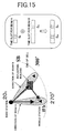
- the mobile station #j which includes the non-directional antenna measures powers of each radio wave beams radiated from the base station 20 0 by using the antenna of the mobile station #j, and selects a beam of which receiving quality such as received signal level is the best (maximum) (in this case, selects the beam which is radiated to the direction of 300° and reflected by the intercepting object SB). Accordingly, communication by using the beam B can be performed in the same way as using the directional antenna. Assignment of time slot is performed in the same way as the case using the directional antenna.
- the mobile station includes the non-directional antenna instead of the directional antenna, a case where the mobile station performs combining of time slots of beams from a plurality of directions as shown in Fig.15 will be described.
- the mobile station When beams from the base station 20 0 is in a state shown in Fig.15, the mobile station combines received signals of the beams A and B instead of selecting one of the beams A and B in which time slots for radio wave radiation are provided if there is an available time slot for each beam. Assignment of time slots is the same as the case where the directional antenna is used.
- the mobile station #j receives radio waves coming from a plurality of directions in which the radio waves arrive at the mobile station in different times.
- path diversity effect can be used by using RAKE receiver in a receiver of CDMA in which signals from a plurality of paths which have time difference are combined.
- a communication control method and apparatus based on SDMA which can decreases interference due to radio wave beams radiated to the mobile station from each base station in a mobile communication system.
Claims (5)
- Kommunikationssteuerverfahren, geeignet zur Verwendung in einem zellularen Mobilkommunikationssystem, in dem jede Basisstation (20) Funkwellenstrahlen in mehrere Richtungen abstrahlen kann und jede Basisstation mit mobilen Stationen (10) über dieselbe Frequenz durch Abstrahlen von Funkwellenstrahlen an die mobilen Stationen kommuniziert, wobei das Verfahren durch die folgenden Schritte gekennzeichnet ist:eine mobile Station empfängt ein Signal über einen ersten Funkwellenstrahl aus einer Richtung einer Basisstation,die mobile Station fragt eine Zuordnung eines Zeitschlitz für einen zweiten Funkwellenstrahl an, wobei der zweite Funkwellenstrahl durch die Basisstation abgestrahlt wird und an der mobilen Station aus einer von dem ersten Funkwellenstrahl verschiedenen Richtung eintrifft;die Basisstation ordnet den Zeitschlitz so zu, dass der Zeitschlitz von der Zeit verschieden ist, zu der andere Basisstationen einen Funkwellenstrahl abstrahlen, der zu einer Störung mit dem zweiten Funkwellenstrahl führen kann; unddie mobile Station kombiniert ein über den ersten Funkwellenstrahl empfangenes Signal und ein über den zweiten Funkwellenstrahl empfangenes Signal.
- Kommunikationssteuerverfahren nach Anspruch 1, wobei das Verfahren den Schritt umfasst:die mobile Station richtet einen Funkwellenstrahl in eine Richtung, aus der der zweite Funkwellenstrahl kommt.
- Kommunikationssteuerverfahren nach Anspruch 2, wobei das Verfahren die Schritte umfasst:wenn sich ein durch einen Funkwellenstrahl empfangener Pegel eines Signals, das aus einer Richtung einer mobilen Station kommt, in einer Basisstation verringert, richtet die Basisstation einen Funkwellenstrahl in eine Richtung, aus der ein anderer Funkwellenstrahl kommt, um einen Pfad aufrechtzuerhalten, wobei der andere Funkwellenstrahl die beste Empfangsqualität der weiteren Funkwellenstrahlen aufweist, die von der mobilen Station an der Basisstation eintreffen.
- Kommunikationssteuerverfahren nach Anspruch 2, wobei das Verfahren die Schritte umfasst:wenn sich ein durch einen Funkwellenstrahl empfangener Pegel eines Signals, das direkt von einer Basisstation kommt, verringert, wählt die mobile Station einen anderen Funkwellenstrahl aus, wobei der andere Funkwellenstrahl die beste Empfangsqualität aus den weiteren Funkwellenstrahlen aufweist, die an der mobilen Station von der Basisstation eintreffen, und fragt die mobile Station eine Zuordnung eines Zeitschlitzes für den anderen Funkwellenstrahl an; unddie Basisstation ordnet den Zeitschlitz so zu, dass der Zeitschlitz von der Zeit verschieden ist, zu der weitere Basisstationen Funkwellenstrahlen abstrahlen, die eine Störung mit dem anderen Funkwellenstrahl verursachen können.
- Mobile Station für ein zellulares mobiles Kommunikationssystem, in dem jede Basisstation (20) einen Funkwellenstrahl an eine mobile Station abstrahlt und jede Basisstation mit einer mobilen Station über dieselbe Frequenz kommuniziert, wobei die mobile Station gekennzeichnet ist durch:ein Teil (31 bis 35) zum Empfangen eines Signals über einen ersten Funkwellenstrahl aus einer Richtung einer Basisstation und zum Richten eines Funkwellenstrahls in eine Richtung, aus der ein zweiter Funkwellenstrahl kommt, wobei der zweite Funkwellenstrahl durch die Basisstation abgestrahlt wird und an der mobilen Station aus einer von dem ersten Funkwellenstrahl verschiedenen Richtung eintrifft;ein Teil zum Anfordern einer Zuordnung eines Zeitschlitzes für den zweiten Funkwellenstrahl;ein Teil zum Kombinieren eines durch einen ersten Funkwellenstrahl empfangenen Signals und eines durch den zweiten Funkwellenstrahl empfangenen Signals, nachdem die Basisstation den Zeitschlitz zugeordnet hat.
Applications Claiming Priority (3)
| Application Number | Priority Date | Filing Date | Title |
|---|---|---|---|
| JP2001037588 | 2001-02-14 | ||
| JP2001037588 | 2001-02-14 | ||
| EP02250993A EP1241906A3 (de) | 2001-02-14 | 2002-02-13 | Kommunikationsregelungsverfahren und Vorrichtung in einem Mobilfunksystem |
Related Parent Applications (1)
| Application Number | Title | Priority Date | Filing Date |
|---|---|---|---|
| EP02250993A Division EP1241906A3 (de) | 2001-02-14 | 2002-02-13 | Kommunikationsregelungsverfahren und Vorrichtung in einem Mobilfunksystem |
Publications (3)
| Publication Number | Publication Date |
|---|---|
| EP1418779A2 EP1418779A2 (de) | 2004-05-12 |
| EP1418779A3 EP1418779A3 (de) | 2004-05-26 |
| EP1418779B1 true EP1418779B1 (de) | 2007-10-03 |
Family
ID=18900689
Family Applications (2)
| Application Number | Title | Priority Date | Filing Date |
|---|---|---|---|
| EP02250993A Withdrawn EP1241906A3 (de) | 2001-02-14 | 2002-02-13 | Kommunikationsregelungsverfahren und Vorrichtung in einem Mobilfunksystem |
| EP04000474A Expired - Lifetime EP1418779B1 (de) | 2001-02-14 | 2002-02-13 | Kommunikationsregelungsverfahren und Vorrichtung in einem Mobilfunksystem |
Family Applications Before (1)
| Application Number | Title | Priority Date | Filing Date |
|---|---|---|---|
| EP02250993A Withdrawn EP1241906A3 (de) | 2001-02-14 | 2002-02-13 | Kommunikationsregelungsverfahren und Vorrichtung in einem Mobilfunksystem |
Country Status (4)
| Country | Link |
|---|---|
| US (1) | US7103022B2 (de) |
| EP (2) | EP1241906A3 (de) |
| CN (1) | CN100459727C (de) |
| DE (1) | DE60222779T2 (de) |
Families Citing this family (66)
| Publication number | Priority date | Publication date | Assignee | Title |
|---|---|---|---|---|
| US20040152492A1 (en) * | 2001-05-14 | 2004-08-05 | Andrew Gray | Antenna interface protocol |
| KR20050090477A (ko) * | 2002-05-13 | 2005-09-13 | 인터디지탈 테크날러지 코포레이션 | 빔을 이용하는 슬롯 코드 분할 다중 접속 시스템에서사용자에게 리소스를 할당하는 방법 |
| US7277730B2 (en) * | 2002-12-26 | 2007-10-02 | Nokia Corporation | Method of allocating radio resources in telecommunication system, and telecommunication system |
| US7020107B2 (en) * | 2003-01-21 | 2006-03-28 | Arraycomm, Llc | Methods for reliable user switchback on a PHS spatial division multiple access channel |
| EP1453337A1 (de) * | 2003-02-27 | 2004-09-01 | Siemens Mobile Communications S.p.A. | Verfahren zur Funkressourcenverwaltung in zellularen Telefonnetzen basierend auf Interferenzverminderung, Zeitschlitzzuweisung und eine adaptative Antennengruppe |
| KR100585726B1 (ko) * | 2003-09-03 | 2006-06-07 | 엘지전자 주식회사 | 이동 단말의 어레이 안테나 빔 형성 방법 및 장치 |
| JP4396416B2 (ja) * | 2003-10-24 | 2010-01-13 | ソニー株式会社 | 無線通信システム、無線通信装置及び無線通信方法、並びにコンピュータ・プログラム |
| US20050141495A1 (en) * | 2003-12-30 | 2005-06-30 | Lin Xintian E. | Filling the space-time channels in SDMA |
| US8385937B2 (en) * | 2004-07-07 | 2013-02-26 | Toshiba America Research Inc. | Load equalizing antennas |
| JP2006217011A (ja) * | 2005-02-01 | 2006-08-17 | Fujitsu Ltd | 移動局、基地局、及び無線通信システム |
| US8126482B2 (en) * | 2005-03-04 | 2012-02-28 | Qualcomm Incorporated | Multiple paging channels for efficient region paging |
| KR100706620B1 (ko) | 2005-05-17 | 2007-04-11 | 한국전자통신연구원 | 스위치 빔을 이용한 초기 동기 시의 빔 선택 방법 |
| US7822000B2 (en) * | 2005-06-30 | 2010-10-26 | Symbol Technologies, Inc. | Time division multiplexing for access ports in a wireless network |
| KR100829817B1 (ko) * | 2006-05-22 | 2008-05-16 | 한국전자통신연구원 | 셀룰러 시스템에서 중계기, 단말 및 기지국, 그리고기지국과 단말을 중계하는 방법 |
| US8243691B2 (en) * | 2007-03-29 | 2012-08-14 | Kyocera Corporation | Communication control method, communication system, communication control apparatus and wireless base station |
| US8576803B2 (en) * | 2007-06-01 | 2013-11-05 | Mitsubishi Electric Corporation | Communication system |
| JP5155697B2 (ja) * | 2008-03-05 | 2013-03-06 | 株式会社東芝 | 無線通信装置 |
| CN101552629B (zh) * | 2008-04-01 | 2012-08-08 | 中国移动通信集团公司 | 一种调整多载波功放工作电压的方法、装置及系统 |
| US8111655B2 (en) * | 2008-08-28 | 2012-02-07 | Airhop Communications, Inc. | System and method of base station performance enhancement using coordinated antenna array |
| IL194364A0 (en) * | 2008-09-25 | 2009-08-03 | Zeev Roth | A method and system for allocating wireless transmission resources |
| EP2317789B1 (de) * | 2009-11-03 | 2016-01-27 | Alcatel Lucent | Verfahren, Basisstation und zellulares Telekommunikationsnetzwerk zur Verbesserung der Dienstqualität |
| JP5310505B2 (ja) * | 2009-11-25 | 2013-10-09 | 富士通株式会社 | 無線通信方法、基地局および移動通信端末 |
| US9048907B2 (en) * | 2010-03-10 | 2015-06-02 | Alcatel Lucent | Methods for reducing interference in communication systems |
| US8971452B2 (en) | 2012-05-29 | 2015-03-03 | Magnolia Broadband Inc. | Using 3G/4G baseband signals for tuning beamformers in hybrid MIMO RDN systems |
| US8649458B2 (en) | 2012-05-29 | 2014-02-11 | Magnolia Broadband Inc. | Using antenna pooling to enhance a MIMO receiver augmented by RF beamforming |
| US8811522B2 (en) | 2012-05-29 | 2014-08-19 | Magnolia Broadband Inc. | Mitigating interferences for a multi-layer MIMO system augmented by radio distribution network |
| US8644413B2 (en) | 2012-05-29 | 2014-02-04 | Magnolia Broadband Inc. | Implementing blind tuning in hybrid MIMO RF beamforming systems |
| US8842765B2 (en) | 2012-05-29 | 2014-09-23 | Magnolia Broadband Inc. | Beamformer configurable for connecting a variable number of antennas and radio circuits |
| US8767862B2 (en) | 2012-05-29 | 2014-07-01 | Magnolia Broadband Inc. | Beamformer phase optimization for a multi-layer MIMO system augmented by radio distribution network |
| US8619927B2 (en) | 2012-05-29 | 2013-12-31 | Magnolia Broadband Inc. | System and method for discrete gain control in hybrid MIMO/RF beamforming |
| US8861635B2 (en) | 2012-05-29 | 2014-10-14 | Magnolia Broadband Inc. | Setting radio frequency (RF) beamformer antenna weights per data-stream in a multiple-input-multiple-output (MIMO) system |
| US8837650B2 (en) | 2012-05-29 | 2014-09-16 | Magnolia Broadband Inc. | System and method for discrete gain control in hybrid MIMO RF beamforming for multi layer MIMO base station |
| US9154204B2 (en) | 2012-06-11 | 2015-10-06 | Magnolia Broadband Inc. | Implementing transmit RDN architectures in uplink MIMO systems |
| WO2014009246A1 (en) * | 2012-07-09 | 2014-01-16 | Nokia Siemens Networks Oy | Millimeterwave access architecture with rapid rerouting |
| US8797969B1 (en) | 2013-02-08 | 2014-08-05 | Magnolia Broadband Inc. | Implementing multi user multiple input multiple output (MU MIMO) base station using single-user (SU) MIMO co-located base stations |
| US9343808B2 (en) | 2013-02-08 | 2016-05-17 | Magnotod Llc | Multi-beam MIMO time division duplex base station using subset of radios |
| US8989103B2 (en) | 2013-02-13 | 2015-03-24 | Magnolia Broadband Inc. | Method and system for selective attenuation of preamble reception in co-located WI FI access points |
| US20140226740A1 (en) | 2013-02-13 | 2014-08-14 | Magnolia Broadband Inc. | Multi-beam co-channel wi-fi access point |
| US9155110B2 (en) | 2013-03-27 | 2015-10-06 | Magnolia Broadband Inc. | System and method for co-located and co-channel Wi-Fi access points |
| US8982853B2 (en) | 2013-03-05 | 2015-03-17 | Qualcomm Incorporated | Methods and apparatus to control interference |
| US9100968B2 (en) | 2013-05-09 | 2015-08-04 | Magnolia Broadband Inc. | Method and system for digital cancellation scheme with multi-beam |
| US9425882B2 (en) | 2013-06-28 | 2016-08-23 | Magnolia Broadband Inc. | Wi-Fi radio distribution network stations and method of operating Wi-Fi RDN stations |
| US8995416B2 (en) | 2013-07-10 | 2015-03-31 | Magnolia Broadband Inc. | System and method for simultaneous co-channel access of neighboring access points |
| US8824596B1 (en) | 2013-07-31 | 2014-09-02 | Magnolia Broadband Inc. | System and method for uplink transmissions in time division MIMO RDN architecture |
| US9497781B2 (en) | 2013-08-13 | 2016-11-15 | Magnolia Broadband Inc. | System and method for co-located and co-channel Wi-Fi access points |
| US9088898B2 (en) | 2013-09-12 | 2015-07-21 | Magnolia Broadband Inc. | System and method for cooperative scheduling for co-located access points |
| US9060362B2 (en) | 2013-09-12 | 2015-06-16 | Magnolia Broadband Inc. | Method and system for accessing an occupied Wi-Fi channel by a client using a nulling scheme |
| US9172454B2 (en) | 2013-11-01 | 2015-10-27 | Magnolia Broadband Inc. | Method and system for calibrating a transceiver array |
| US8891598B1 (en) | 2013-11-19 | 2014-11-18 | Magnolia Broadband Inc. | Transmitter and receiver calibration for obtaining the channel reciprocity for time division duplex MIMO systems |
| US8942134B1 (en) | 2013-11-20 | 2015-01-27 | Magnolia Broadband Inc. | System and method for selective registration in a multi-beam system |
| US8929322B1 (en) | 2013-11-20 | 2015-01-06 | Magnolia Broadband Inc. | System and method for side lobe suppression using controlled signal cancellation |
| US9014066B1 (en) | 2013-11-26 | 2015-04-21 | Magnolia Broadband Inc. | System and method for transmit and receive antenna patterns calibration for time division duplex (TDD) systems |
| US9294177B2 (en) | 2013-11-26 | 2016-03-22 | Magnolia Broadband Inc. | System and method for transmit and receive antenna patterns calibration for time division duplex (TDD) systems |
| US9042276B1 (en) | 2013-12-05 | 2015-05-26 | Magnolia Broadband Inc. | Multiple co-located multi-user-MIMO access points |
| JP2017504264A (ja) * | 2014-01-07 | 2017-02-02 | クインテル テクノロジー リミテッド | セクタ間干渉緩和に優れたアンテナシステム |
| US9172446B2 (en) | 2014-03-19 | 2015-10-27 | Magnolia Broadband Inc. | Method and system for supporting sparse explicit sounding by implicit data |
| US9100154B1 (en) | 2014-03-19 | 2015-08-04 | Magnolia Broadband Inc. | Method and system for explicit AP-to-AP sounding in an 802.11 network |
| US9271176B2 (en) | 2014-03-28 | 2016-02-23 | Magnolia Broadband Inc. | System and method for backhaul based sounding feedback |
| US10820280B2 (en) | 2015-09-29 | 2020-10-27 | Huawei Technologies Co., Ltd. | Method for controlling transmit power of wireless communications terminal, and wireless communications terminal |
| EP3491746A1 (de) * | 2016-08-12 | 2019-06-05 | Sony Corporation | Telekommunikationsvorrichtung und -verfahren |
| US20180054744A1 (en) * | 2016-08-16 | 2018-02-22 | Futurewei Technologies, Inc. | Apparatus, computer program, and method for timing-based restriction of a data signaling direction |
| EP3574673A4 (de) * | 2017-05-09 | 2020-09-23 | Telefonaktiebolaget LM Ericsson (publ) | Verfahren und vorrichtung zum senden und empfangen von daten |
| KR102420252B1 (ko) * | 2017-12-19 | 2022-07-13 | 삼성전자주식회사 | 무선 통신 시스템에서 측정 구성을 위한 장치 및 방법 |
| CN112005564B (zh) * | 2018-02-15 | 2023-02-28 | 诺基亚技术有限公司 | 增强通信 |
| US11336346B2 (en) * | 2018-07-27 | 2022-05-17 | Asustek Computer Inc. | Method and apparatus for handling beam sensing for sidelink resource in a wireless communication system |
| US10791561B2 (en) * | 2018-08-29 | 2020-09-29 | Qualcomm Incorporated | Elevation restriction beamforming in wireless systems |
Family Cites Families (11)
| Publication number | Priority date | Publication date | Assignee | Title |
|---|---|---|---|---|
| US4513412A (en) * | 1983-04-25 | 1985-04-23 | At&T Bell Laboratories | Time division adaptive retransmission technique for portable radio telephones |
| US5095535A (en) * | 1988-07-28 | 1992-03-10 | Motorola, Inc. | High bit rate communication system for overcoming multipath |
| SE8803094D0 (sv) | 1988-09-05 | 1988-09-05 | Joakim Nelson | Ytteckande tradlosa telekommunikationssystem med tids, frekvens och rymdstyrning |
| US6091936A (en) * | 1996-03-29 | 2000-07-18 | Ericsson Inc. | Method and apparatus for reducing co-channel interference |
| CA2216761C (en) | 1996-11-08 | 2002-01-01 | Lucent Technologies Inc. | Tdm-based fixed wireless loop system |
| JPH10248086A (ja) | 1997-03-05 | 1998-09-14 | Nippon Telegr & Teleph Corp <Ntt> | アクセスチャネル配置方法 |
| US6185258B1 (en) | 1997-09-16 | 2001-02-06 | At&T Wireless Services Inc. | Transmitter diversity technique for wireless communications |
| US6266330B1 (en) * | 1998-01-22 | 2001-07-24 | Nokia Mobile Phones Limited | Dynamic allocation of radio capacity in TDMA system |
| EP0948229A1 (de) | 1998-04-03 | 1999-10-06 | Lucent Technologies Inc. | Verfahren zur Kanalzuweisung in einem zellularen Funkkommunikationssystem |
| JP3407671B2 (ja) | 1998-06-01 | 2003-05-19 | 三菱電機株式会社 | 無線通信システム及びその基地局 |
| FR2780817B1 (fr) | 1998-07-06 | 2007-09-14 | Sfr Sa | Procede d'orientation de faisceau(x) rayonnant(s) radioelectrique(s) pour la communication entre une station de base et un radiotelephone mobile, et station de base correspondante |
-
2002
- 2002-02-13 US US10/073,317 patent/US7103022B2/en not_active Expired - Fee Related
- 2002-02-13 EP EP02250993A patent/EP1241906A3/de not_active Withdrawn
- 2002-02-13 EP EP04000474A patent/EP1418779B1/de not_active Expired - Lifetime
- 2002-02-13 DE DE60222779T patent/DE60222779T2/de not_active Expired - Lifetime
- 2002-02-19 CN CNB021047766A patent/CN100459727C/zh not_active Expired - Fee Related
Also Published As
| Publication number | Publication date |
|---|---|
| US20020115474A1 (en) | 2002-08-22 |
| EP1241906A3 (de) | 2002-11-27 |
| CN1371221A (zh) | 2002-09-25 |
| DE60222779T2 (de) | 2008-07-03 |
| DE60222779D1 (de) | 2007-11-15 |
| US7103022B2 (en) | 2006-09-05 |
| CN100459727C (zh) | 2009-02-04 |
| EP1418779A2 (de) | 2004-05-12 |
| EP1418779A3 (de) | 2004-05-26 |
| EP1241906A2 (de) | 2002-09-18 |
Similar Documents
| Publication | Publication Date | Title |
|---|---|---|
| EP1418779B1 (de) | Kommunikationsregelungsverfahren und Vorrichtung in einem Mobilfunksystem | |
| US5564121A (en) | Microcell layout having directional and omnidirectional antennas defining a rectilinear layout in a building | |
| KR101839808B1 (ko) | 이동 단말기 및 그 통신방법, 기지국 컨트롤 장치 및 그 컨트롤 방법, 및 그것을 이용하는 다중 협력 송수신 시스템 및 그 방법 | |
| JP4071829B2 (ja) | ビーム形成制御チャネルを有する通信システムおよびシステム制御の方法 | |
| WO2018219236A1 (en) | Methods and system for lbt threshold setting for directional reception and transmission | |
| US20010016504A1 (en) | Method and system for handling radio signals in a radio base station | |
| JP3001570B1 (ja) | 適応アンテナ指向性制御方法及びそのシステム | |
| US7120467B2 (en) | Radio communication method and base station | |
| KR101791270B1 (ko) | 이동통신 시스템에서 공동으로 신호를 송수신하는 통신 방법 및 장치 | |
| EP1432144B1 (de) | Basisstation und Verfahren zur Richtstrahlkommunikation | |
| JP2002536941A (ja) | アンテナ・アレイ・システム | |
| JPH09284200A (ja) | 無線通信装置及び無線通信方法 | |
| KR20000023552A (ko) | 페이징 및 초기 트래픽 채널 전력에 대한 cdma 전력제어 | |
| JPH10507040A (ja) | ハンドオーバー方法及びセルラー通信システム | |
| JP3618719B2 (ja) | 移動通信システムにおける通信制御方法及び装置 | |
| KR20060081194A (ko) | 다중 안테나 시스템에서 섹터 구성 장치 및 방법 | |
| US20230209510A1 (en) | Radio communication method, radio communication system, radio base station, and repeater | |
| JP2001268004A (ja) | アンテナ指向性制御方法および無線装置 | |
| JPH11308662A (ja) | 移動体通信システム、基地局及び基地局制御装置 | |
| JP2002058061A (ja) | アダプティブアレイ基地局による物理スロットの割当て方法 | |
| JP3639168B2 (ja) | 通信制御方法、移動通信システム、基地局及び移動局 | |
| WO2004068842A2 (en) | Methods for reliable user switchback on a phs spatial division multiple access channel | |
| KR100465297B1 (ko) | 어레이 안테나를 이용한 무선통신시스템의 신호 수신 방법 | |
| JP5066162B2 (ja) | アダプティブアレイ基地局およびアダプティブアレイ基地局による物理スロットの割当て方法 | |
| Fujii et al. | Analysis of downlink capacity and transmitter power using SIR‐based adaptive transmitter power control in DS‐CDMA systems—consideration of both common control channel and traffic channels |
Legal Events
| Date | Code | Title | Description |
|---|---|---|---|
| PUAI | Public reference made under article 153(3) epc to a published international application that has entered the european phase |
Free format text: ORIGINAL CODE: 0009012 |
|
| PUAL | Search report despatched |
Free format text: ORIGINAL CODE: 0009013 |
|
| 17P | Request for examination filed |
Effective date: 20040113 |
|
| AC | Divisional application: reference to earlier application |
Ref document number: 1241906 Country of ref document: EP Kind code of ref document: P |
|
| AK | Designated contracting states |
Kind code of ref document: A2 Designated state(s): DE GB |
|
| AK | Designated contracting states |
Kind code of ref document: A3 Designated state(s): DE GB |
|
| 17Q | First examination report despatched |
Effective date: 20041007 |
|
| AKX | Designation fees paid |
Designated state(s): DE GB |
|
| GRAP | Despatch of communication of intention to grant a patent |
Free format text: ORIGINAL CODE: EPIDOSNIGR1 |
|
| GRAS | Grant fee paid |
Free format text: ORIGINAL CODE: EPIDOSNIGR3 |
|
| GRAA | (expected) grant |
Free format text: ORIGINAL CODE: 0009210 |
|
| AC | Divisional application: reference to earlier application |
Ref document number: 1241906 Country of ref document: EP Kind code of ref document: P |
|
| AK | Designated contracting states |
Kind code of ref document: B1 Designated state(s): DE GB |
|
| REG | Reference to a national code |
Ref country code: GB Ref legal event code: FG4D |
|
| REF | Corresponds to: |
Ref document number: 60222779 Country of ref document: DE Date of ref document: 20071115 Kind code of ref document: P |
|
| PLBE | No opposition filed within time limit |
Free format text: ORIGINAL CODE: 0009261 |
|
| STAA | Information on the status of an ep patent application or granted ep patent |
Free format text: STATUS: NO OPPOSITION FILED WITHIN TIME LIMIT |
|
| 26N | No opposition filed |
Effective date: 20080704 |
|
| PGFP | Annual fee paid to national office [announced via postgrant information from national office to epo] |
Ref country code: GB Payment date: 20130213 Year of fee payment: 12 Ref country code: DE Payment date: 20130206 Year of fee payment: 12 |
|
| REG | Reference to a national code |
Ref country code: DE Ref legal event code: R119 Ref document number: 60222779 Country of ref document: DE |
|
| REG | Reference to a national code |
Ref country code: DE Ref legal event code: R079 Ref document number: 60222779 Country of ref document: DE Free format text: PREVIOUS MAIN CLASS: H04Q0007360000 Ipc: H04W0016000000 |
|
| GBPC | Gb: european patent ceased through non-payment of renewal fee |
Effective date: 20140213 |
|
| REG | Reference to a national code |
Ref country code: DE Ref legal event code: R079 Ref document number: 60222779 Country of ref document: DE Free format text: PREVIOUS MAIN CLASS: H04Q0007360000 Ipc: H04W0016000000 Effective date: 20141028 Ref country code: DE Ref legal event code: R119 Ref document number: 60222779 Country of ref document: DE Effective date: 20140902 |
|
| PG25 | Lapsed in a contracting state [announced via postgrant information from national office to epo] |
Ref country code: GB Free format text: LAPSE BECAUSE OF NON-PAYMENT OF DUE FEES Effective date: 20140213 Ref country code: DE Free format text: LAPSE BECAUSE OF NON-PAYMENT OF DUE FEES Effective date: 20140902 |