EP1418685A1 - Radio base system; transmission directional control method; and transmission directional control program - Google Patents
Radio base system; transmission directional control method; and transmission directional control program Download PDFInfo
- Publication number
- EP1418685A1 EP1418685A1 EP02745989A EP02745989A EP1418685A1 EP 1418685 A1 EP1418685 A1 EP 1418685A1 EP 02745989 A EP02745989 A EP 02745989A EP 02745989 A EP02745989 A EP 02745989A EP 1418685 A1 EP1418685 A1 EP 1418685A1
- Authority
- EP
- European Patent Office
- Prior art keywords
- transmission
- response vector
- reception
- estimating
- vector
- Prior art date
- Legal status (The legal status is an assumption and is not a legal conclusion. Google has not performed a legal analysis and makes no representation as to the accuracy of the status listed.)
- Withdrawn
Links
Images




Classifications
-
- H—ELECTRICITY
- H04—ELECTRIC COMMUNICATION TECHNIQUE
- H04B—TRANSMISSION
- H04B7/00—Radio transmission systems, i.e. using radiation field
- H04B7/02—Diversity systems; Multi-antenna system, i.e. transmission or reception using multiple antennas
- H04B7/04—Diversity systems; Multi-antenna system, i.e. transmission or reception using multiple antennas using two or more spaced independent antennas
- H04B7/0413—MIMO systems
- H04B7/0452—Multi-user MIMO systems
-
- H—ELECTRICITY
- H04—ELECTRIC COMMUNICATION TECHNIQUE
- H04B—TRANSMISSION
- H04B7/00—Radio transmission systems, i.e. using radiation field
- H04B7/02—Diversity systems; Multi-antenna system, i.e. transmission or reception using multiple antennas
- H04B7/04—Diversity systems; Multi-antenna system, i.e. transmission or reception using multiple antennas using two or more spaced independent antennas
- H04B7/06—Diversity systems; Multi-antenna system, i.e. transmission or reception using multiple antennas using two or more spaced independent antennas at the transmitting station
- H04B7/0613—Diversity systems; Multi-antenna system, i.e. transmission or reception using multiple antennas using two or more spaced independent antennas at the transmitting station using simultaneous transmission
- H04B7/0615—Diversity systems; Multi-antenna system, i.e. transmission or reception using multiple antennas using two or more spaced independent antennas at the transmitting station using simultaneous transmission of weighted versions of same signal
-
- H—ELECTRICITY
- H04—ELECTRIC COMMUNICATION TECHNIQUE
- H04B—TRANSMISSION
- H04B7/00—Radio transmission systems, i.e. using radiation field
- H04B7/02—Diversity systems; Multi-antenna system, i.e. transmission or reception using multiple antennas
- H04B7/04—Diversity systems; Multi-antenna system, i.e. transmission or reception using multiple antennas using two or more spaced independent antennas
- H04B7/08—Diversity systems; Multi-antenna system, i.e. transmission or reception using multiple antennas using two or more spaced independent antennas at the receiving station
- H04B7/0837—Diversity systems; Multi-antenna system, i.e. transmission or reception using multiple antennas using two or more spaced independent antennas at the receiving station using pre-detection combining
- H04B7/0842—Weighted combining
- H04B7/086—Weighted combining using weights depending on external parameters, e.g. direction of arrival [DOA], predetermined weights or beamforming
Definitions
- the present invention relates to a radio base station system as well as a method and a program for controlling transmission directivity, and more particularly to a radio base station system in which directivity of an array antenna is modified in real time so that signals are transmitted/received to/from a plurality of mobile terminals in a mobile communication system, as well as a method and a program for controlling transmission directivity in such a radio base station system.
- PHS Personal Handyphone System
- the adaptive array processing is a well-known processing, in which, based on signals received from a plurality of terminals by an array antenna of the base station, a reception weight vector consisting of weights for respective antennas constituting the array antenna is calculated and adaptively controlled, thereby accurately extracting a signal from a specific terminal.
- a reception weight vector calculator calculating such a reception weight vector for each symbol in the reception signal.
- the reception weight vector calculator performs a processing to converge the reception weight vector so as to reduce a mean square of an error between the sum of complex multiplication of the reception signal by a calculated reception weight vector and a known reference signal, that is, the adaptive array processing to converge reception directivity from the specific terminal.
- the reception weight vector is adaptively converged in accordance with time and fluctuation of a property of a propagation path for a signal radio wave, so that an interfering component or noise is eliminated from the reception signal, to extract the reception signal from the specific terminal.
- a transmission weight vector calculator calculating a transmission weight vector for each symbol in a transmission signal is provided.
- the transmission signal weighted with the transmission weight vector calculated by the transmission weight vector calculator is transmitted with the same array antenna as in reception.
- the transmission weight vector calculator duplicates the reception weight vector as it is for use as the transmission weight vector, the transmission signal is weighted to target the same, specific terminal as in reception. In such a case, a transmitted radio wave signal is emitted as if it had transmission directivity to that terminal.
- a method of calculating a transmission weight vector for a downlink taking into account fluctuation in a propagation environment (fading) mainly due to travel of the terminal, a method with which a transmission response (coefficient) vector in the downlink is estimated with a extrapolation processing using a reception response (coefficient) vector obtained in the uplink, and the transmission weight vector is calculated based on the estimated transmission response vector, has been proposed.
- the reception response vector is measured at a plurality of timings in the uplink in a frame, and based on the measurement value, a time waveform of the reception response vector is subjected to multiple-order extrapolation (for example, first-order extrapolation or second-order extrapolation). Then, the reception response vector at an arbitrary transmission timing in the downlink is estimated, and this will serve as the transmission response vector.
- the transmission weight vector is thus calculated.
- FD Doppler frequency
- An object of the present invention is to provide a radio base station system, as well as a method and a program for controlling transmission directivity, with which a transmission response vector in a downlink can accurately be estimated, and transmission directivity can sufficiently be controlled, even if the moving speed of the terminal is increased, and the Doppler frequency is raised.
- a radio base station system transmitting/receiving signals to/from a plurality of terminals using a plurality of antennas arranged in a discrete manner, includes reception signal separation means, reception response vector estimation means, transmission response vector estimation means, and transmission directivity control means.
- the reception signal separation means calculates a weight vector for separating a signal from a specific terminal among the plurality of terminals, based on signals received with the plurality of antennas.
- the reception response vector estimation means estimates a reception response vector of a propagation path from the specific terminal, based on signals received with the plurality of antennas.
- the transmission response vector estimation means estimates a transmission response vector of the propagation path in transmission, based on an estimation result of the reception response vector estimation means.
- the transmission directivity control means controls transmission directivity of the antennas, based on an estimation result of the transmission response vector estimation means.
- the transmission response vector estimation means includes vector prediction means which regards a function of temporal change of an element for each antenna of the reception response vector estimated by the reception response vector estimation means, as a composite waveform of signal waveforms of a prescribed number of prescribed frequency components which are different from each other, predicts temporal changes at arbitrary timing positions in transmission, of the signal waveforms of respective frequency components, and synthesizes the transmission response vector.
- the vector prediction means includes coefficient estimation means and calculation means.
- the coefficient estimation means estimates coefficients of the signal waveforms of the respective frequency components.
- the calculation means calculates the transmission response vector at the arbitrary timing position in transmission, based on the estimated coefficients and the prescribed frequency components.
- the radio base station system further includes moving speed detecting means detecting a Doppler frequency representing a moving speed of the terminal.
- the coefficient estimation means determines the prescribed frequency components which are different from each other, in accordance with the detected Doppler frequency.
- the coefficient estimation means determines the prescribed frequency components which are different from each other so as to have a prescribed relation with a maximum value for the detected Doppler frequency.
- the transmission directivity control means controls transmission directivity of the antenna, based on the weight vector calculated by the reception signal separation means instead of the estimation result of the transmission response vector estimation means, when the detected Doppler frequency takes a value within a range indicating that the terminal has hardly moved.
- the coefficient estimation means estimates the coefficients by solving simultaneous equations having the coefficients as unknown quantity, obtained by estimating the reception response vector at timing positions in a number at least equal to that of the frequency components which are different from each other.
- transmission and reception of the signal is performed in a time-divided manner in a plurality of time slots respectively.
- the coefficient estimation means sets a timing position estimating the reception response vector in any one of the plurality of time slots for reception.
- transmission and reception of the signal is performed in a time-divided manner in a plurality of time slots respectively.
- the coefficient estimation means distributes and sets timing positions estimating the reception response vector in at least two slots among the plurality of time slots for reception.
- a method of controlling transmission directivity in a radio base station system transmitting/receiving signals to/from a plurality of terminals using a plurality of antennas arranged in a discrete manner includes the steps of: calculating a weight vector for separating a signal from a specific terminal among the plurality of terminals, based on signals received with the plurality of antennas; estimating a reception response vector of a propagation path from the specific terminal, based on signals received with the plurality of antennas; estimating a transmission response vector of the propagation path in transmission, based on the estimated reception response vector; and controlling transmission directivity of the antennas, based on the estimated transmission response vector.
- the step of estimating the transmission response vector includes the steps of: regarding a function of temporal change of an element of each antenna of the estimated reception response vector as a composite waveform of signal waveforms of a prescribed number of prescribed frequency components which are different from each other; predicting temporal changes at arbitrary timing positions in transmission, of the signal waveforms of respective frequency components; and synthesizing the transmission response vector.
- the step of synthesizing includes the steps of estimating coefficients of the signal waveform of the respective frequency components, and calculating the transmission response vector at the arbitrary timing position in transmission, based on the estimated coefficients and the prescribed frequency components.
- the method of controlling transmission directivity further includes the step of detecting a Doppler frequency representing a moving speed of the terminal.
- the step of estimating the coefficient includes the step of determining the prescribed frequency components which are different from each other, in accordance with the detected Doppler frequency.
- the step of estimating the coefficient includes the step of determining the prescribed frequency components which are different from each other so as to have a prescribed relation with a maximum value for the detected Doppler frequency.
- the step of controlling transmission directivity of the antenna includes the step of controlling transmission directivity of the antenna, based on the calculated weight vector instead of the estimated transmission response vector, when the detected Doppler frequency takes a value within a range indicating that the terminal has hardly moved.
- the step of estimating the coefficient includes the step of estimating the coefficients by solving simultaneous equations having the coefficients as unknown quantity, obtained by estimating the reception response vector at timing positions in a number at least equal to a number of the frequency components which are different from each other.
- transmission and reception of the signal is performed in a time-divided manner in a plurality of time slots respectively.
- a timing position estimating the reception response vector is set in any one of the plurality of time slots for reception.
- transmission and reception of the signal is performed in a time-divided manner in a plurality of time slots respectively.
- timing positions estimating the reception response vector are distributed and set in at least two slots among the plurality of time slots for reception.
- a program for controlling transmission directivity in a radio base station system transmitting/receiving signals to/from a plurality of terminals using a plurality of antennas arranged in a discrete manner causes a computer to execute the steps of: calculating a weight vector for separating a signal from a specific terminal among the plurality of terminals, based on signals received with the plurality of antennas; estimating a reception response vector of a propagation path from the specific terminal, based on signals received with the plurality of antennas; estimating a transmission response vector of the propagation path in transmission, based on the estimated reception response vector; and controlling transmission directivity of the antennas, based on the estimated transmission response vector.
- the step of estimating the transmission response vector includes the steps of: regarding a function of temporal change of an element of each antenna of the estimated reception response vector as a composite waveform of signal waveforms of a prescribed number of prescribed frequency components which are different from each other; predicting temporal changes at arbitrary timing positions in transmission, of the signal waveforms of respective frequency components; and synthesizing the transmission response vector.
- the step of synthesizing includes the steps of estimating coefficients of the signal waveforms of the respective frequency components, and calculating the transmission response vector at the arbitrary timing position in transmission, based on the estimated coefficients and the prescribed frequency components.
- the program for controlling transmission directivity further causes the computer to execute the step of detecting a Doppler frequency representing a moving speed of the terminal.
- the step of estimating the coefficient includes the step of determining the prescribed frequency components which are different from each other, in accordance with the detected Doppler frequency.
- the step of estimating the coefficient includes the step of determining the prescribed frequency components which are different from each other so as to have a prescribed relation with a maximum value for the detected Doppler frequency.
- the step of controlling transmission directivity of the antenna includes the step of controlling transmission directivity of the antenna, based on the calculated weight vector instead of the estimated transmission response vector, when the detected Doppler frequency takes a value within a range indicating that the terminal has hardly moved.
- the step of estimating the coefficient includes the step of estimating the coefficients by solving simultaneous equations having the coefficients as unknown quantity, obtained by estimating the reception response vector at timing positions in a number at least equal to a number of the frequency components which are different from each other.
- transmission and reception of the signal is performed in a time-divided manner in a plurality of time slots respectively.
- a timing position estimating the reception response vector is set in any one of the plurality of time slots for reception.
- transmission and reception of the signal is performed in a time-divided manner in a plurality of time slots respectively.
- timing positions estimating the reception response vector are distributed and set in at least two slots among the plurality of time slots for reception.
- temporal change of the reception response vector due to change in the propagation environment is represented as a composite of signal waveforms of a plurality of frequencies.
- Change in transmission for each of a prescribed number of prescribed frequency components which are different from each other is predicted and combined, whereby the reception response vector at that time is estimated and used for controlling transmission directivity in the radio base station system. Therefore, compared to an example in which the reception response vector in transmission is estimated with the extrapolation processing, more accurate control of transmission directivity can be achieved.
- the terminal moves with a high speed, and the Doppler frequency is high, spatial multiple access of a plurality of terminals to the radio base station system can be maintained.
- Fig. 5 is a functional block diagram for functionally illustrating a configuration of a base station 1000 for estimating a transmission response vector with the conventional extrapolation processing performed with software by a digital signal processor (DSP).
- DSP digital signal processor
- N antennas N: natural number
- a reception portion SR1 for separating a signal of a corresponding user, for example, user PS1, upon receiving signals from antennas #1 to #4, and a transmission portion ST1 for transmitting a signal to user PS1 are provided. Connection of antennas #1 to #4 to reception portion SR1 and transmission portion ST1 can selectively be switched by switches 10-1 to 10-4.
- reception signals RX 1 (t), RX 2 (t), RX 3 (t), RX 4 (t) received at antennas #1 to #4 respectively are represented in the following equations.
- RX 1 (t) h 11 Srx 1 (t) + h 12 Srx 2 (t) + n 1 (t)
- RX 2 (t) h 21 Srx 1 (t) + h 22 Srx 2 (t) + n 2 (t)
- RX 3 (t) h 31 Srx 1 (t) + h 32 Srx 2 (t) + n 3 (t)
- RX 4 (t) h 41 Srx 1 (t) + h 42 Srx 2 (t) + n 4 (t)
- signals Srx 1 (t) and Srx 2 (t) represent signals transmitted from user PS1 and user PS2 respectively
- coefficients h 11 , h 21 , h 31 , h 41 represent complex coefficients of the signal from user PS1 received at antennas #1 to #4 respectively
- coefficients h 12 , h 22 , h 32 , h 42 represent complex coefficients of the signal from user PS2 received at antennas #1 to #4 respectively.
- n 1 (t), n 2 (t), n 3 (t), n 4 (t) represent noise components contained in signals received at antennas #1 to #4 respectively.
- reception signals RX 1 (t), RX 2 (t), RX 3 (t), RX 4 (t) received at antennas #1 to #4 respectively enter reception portion SR1 through corresponding switches 10-1, 10-2, 10-3, 10-4, and are provided to reception weight vector calculator 20, reception response vector calculator 22 as well as to one inputs of corresponding multipliers 12-1, 12-2, 12-3, 12-4.
- Weight coefficients wrx11, wrx 21, wrx31, wrx 41 with respect to the reception signal at respective antennas are applied to the other inputs of these multipliers from reception weight vector calculator 20. These weight coefficients are calculated in real time by reception weight vector calculator 20.
- Reception weight vector calculator 20 uses an adaptive array algorithm such as RLS (Recursive Least Squares) algorithm or SMI (Sample Matrix Inversion) algorithm, to calculate the reception weight vector consisting of these weight coefficients.
- RLS Recursive Least Squares
- SMI Sample Matrix Inversion
- reception response vector calculator 22 shown in Fig. 5 A basic operation of such reception response vector calculator 22 shown in Fig. 5 is well-known, and described in detail, for example, in International Publication No. WO 00/79702, which is commonly assigned. Therefore, description therefor will not be provided.
- transmission portion ST1 includes a transmission response vector estimator 32 finding a transmission response (coefficient) vector by estimating a propagation path in transmission, that is, estimating an imaginary reception response vector at a time point of transmission, upon receiving the reception response vector calculated in reception response vector calculator 22, as described later; a memory 34 communicating data with transmission response vector estimator 32, and storing and holding the data; a transmission weight vector calculator 30 calculating a transmission weight vector based on an estimation result of transmission response vector estimator 32; and multipliers 15-1, 15-2, 15-3, 15-4 receiving a transmission signal at one input respectively, and having weight coefficients wtx11, wtx21, wtx31, wtx41 from transmission weight vector calculator 30 applied to the other input. Outputs from multipliers 15-1, 15-2, 15-3, 15-4 are provided to antennas #1 to #4 via switches 10-1 to 10-4.
- reception portion SR1 and transmission portion ST1 are provided for each user.
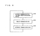
- Fig. 6 is a flowchart for illustrating an outline of a basic operation of base station 1000 in Fig. 5, adopting the conventional extrapolation processing.
- the weight vector (the weight coefficient vector) of the adaptive array can uniquely be represented by a response vector at each antenna element.
- the transmission weight vector is indirectly estimated by estimating temporal fluctuation of the reception response vector with the above-described extrapolation processing until a time point of transmission.
- reception portion SR1 the propagation path for the reception signal is estimated based on the reception signal (step S100).
- reception response vector H 1 can be estimated by reception response vector calculator 22, for example, the propagation path in receiving the signal from user PS1 can be estimated.
- transmission response vector estimator 32 predicts the propagation path in transmission, that is, predicts the reception response vector at the time point of transmission based on the reception response vector in reception, using the conventional extrapolation processing described below (step S102).
- the predicted reception response vector is comparable to the transmission response vector in transmission.
- transmission weight vector calculator 30 uses an algorithm such as Wiener solution, to calculate the transmission weight vector based on the estimated transmission response vector, for output to multipliers 15-1 to 15-4 (step S104).
- Wiener solution an algorithm such as Wiener solution
- a calculation principle of the transmission weight vector is well-known, and described in detail, for example, in International Publication No. WO 00/79702, which is commonly assigned. Therefore, description therefor will not be provided.
- Fig. 7 is a conceptual view for illustrating a basic operation of transmission response vector estimator 32 shown in Fig. 5, that is, estimation of the transmission response vector with the conventional extrapolation processing.
- a frame configuration consisting of 8 slots that is, a configuration in which 4 users are assigned to the uplink and the downlink respectively.
- the uplink is constituted with four reception slots RX1, RX2, RX3 and RX4, while the downlink is constituted with four transmission slots TX1, TX2, not-shown TX3 and TX4. It is to be noted that one slot has 120 symbols.
- transmission response vector estimator 32 receives from reception response vector calculator 22, a measurement value of the reception response vector at three points in the first slot RX1 among four slots in reception (uplink), and stores the result in memory 34. Then, transmission response vector estimator 32 estimates the reception response vector in the first slot TX1 among four slots in transmission (downlink) with the extrapolation processing based on the measurement value.
- the abscissa represents the time base, while the ordinate represents the reception response vector.
- the reception response vector measured at a timing x2 (18th symbol) corresponding to the front edge of the first slot RX1 in the uplink is represented as y2;
- the reception response vector measured at a timing x1 (43rd symbol) corresponding to the center portion of that slot RX1 is represented as y1;
- the reception response vector measured at a timing x0 (68th symbol) corresponding to the rear edge of that slot RX1 is represented as y0.
- Transmission weight vector calculator 30 in Fig. 5 calculates the transmission weight vector using the algorithm such as Wiener solution, based on transmission response vector y(t) estimated through second-order extrapolation in this manner. Transmission directivity is thus controlled.
- the extrapolation error may be large.
- FD if FD exceeds approximately 40Hz, the base station can no longer maintain spatial multiple access.
- the present invention aims to implement correct transmission directivity even in an environment where the Doppler frequency FD is high, by accurately estimating the reception response vector at a timing of the downlink without using the extrapolation processing.
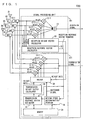
- Fig. 1 is a functional block diagram for functionally illustrating a configuration of a base station 2000 according to the embodiment of the present invention, performed with software by the DSP.
- Base station 2000 shown in Fig. 1 is different from base station 1000 shown in Fig. 5 in the following points.
- the reception response vector supplied from reception response vector calculator 22 is provided to a transmission response vector estimator 40 as well as to a moving speed determination portion 36.
- Moving speed determination portion 36 detects the Doppler frequency FD corresponding to the moving speed of the terminal, from the provided reception response vector.
- the detected FD is provided to transmission response vector estimator 40.
- moving speed determination portion 36 generates a switching signal based on a value of the detected FD, and provides the signal to a switch control input of a switch 38.
- a determination principle by moving speed determination portion 36 will now be described.
- a propagation environment of the propagation path is represented in accordance with fluctuation of the reception coefficient of the propagation path, that is, the degree of fading.
- the degree of fading is represented as a physical value with the Doppler frequency FD.
- the Doppler frequency FD in the propagation environment is estimated in the following manner, for example.
- a correlation value of two reception response vectors arriving at different time, of the reception signal for each user, separated by the adaptive array processing, is calculated. Without fading, two reception response vectors will match, and the correlation value will attain 1. On the other hand, if the fading is significant, a difference between reception response vectors will be large, and the correlation value will be smaller.
- moving speed determination portion 36 can estimate the Doppler frequency FD at that time by calculating the correlation value of the reception response vectors.
- Transmission response vector estimator 40 estimates the transmission response vector in accordance with the estimation principle of the present invention described later, based on the provided reception response vector and the Doppler frequency FD.
- Transmission weight vector calculator 30 calculates the transmission weight vector using the well-known algorithm such as Wiener solution, based on the estimated transmission response vector.
- Switch 38 has its one input provided with the reception weight vector calculated by reception weight vector calculator 20, and has the other input provided with the transmission weight vector calculated by transmission weight vector calculator 30.
- a switching signal selecting the reception weight vector from reception weight vector calculator 20 when the Doppler frequency FD is determined as lower than approximately 10Hz, and selecting the transmission weight vector from transmission weight vector calculator 30 when it is determined as higher than approximately 10Hz, is provided to a switch control input of switch 38 from moving speed determination portion 36.
- the weight vector selected by switch 38 is provided to one inputs of multipliers 15-1, 15-2, 15-3, 15-4 respectively. Configuration and operation of other portion in base station 2000 shown in Fig. 1 are similar to those in base station 1000 shown in Fig. 5, and description therefor will not be repeated.
- Fig. 2 is a conceptual view illustrating the estimation principle of the transmission response vector according to the present invention.
- (A) represents a waveform schematically showing a temporal change along the time base (the abscissa) of an element (coefficient) h i corresponding to an ith antenna among elements (coefficients) for respective antennas constituting reception response vector H.
- a function of temporal change of (A) in Fig. 2 can be regarded as a composite waveform of signal waveforms of some frequency components which are different from each another.
- waveform (A) can be regarded as a composite waveform of a signal waveform (B) of a first frequency, a signal waveform (C) of a higher, second frequency, and a signal waveform (D) of a higher, third frequency.
- h i (t) A i,1 cos( ⁇ 1 t) + A i,2 cos( ⁇ 2 t) + ••• + A i,x-1 cos( ⁇ x-1 t) + A i,x cos( ⁇ x t)
- coefficients A i,1 to A i,x can be estimated, because those coefficients are constants that do not change over time. If these coefficients A i,1 to A i,x are estimated, an element in the transmission response vector at an arbitrary timing t in the transmission slot in the downlink can be obtained from h i (t) in the above equation (3).
- a value of the function of temporal change h i (t) of each element in the reception response vector can directly be measured by reception response vector calculator 22 in a section of the reception slot (uplink).
- the number of coefficients A i,1 to A i,x is x. Therefore, when the value for the reception response vector is measured at M timings, which is equal to or larger than x, within the section in one slot in reception, M measurement values represented in the equations below will be obtained at respective M timings t 1 to t M .
- h i (t 1 ) A i,1 cos( ⁇ 1 t 1 ) + A i,2 cos( ⁇ 2 t 1 ) + ••• + A i,x-1 cos( ⁇ x-1 t 1 ) + A i,x cos( ⁇ x t 1 )
- the above equations (4) will be represented as simultaneous equations, having coefficients A i,1 to A i,x as unknown quantity.
- the number of measurement timings M of the reception response vector is equal to or larger than x, that is, the number of frequencies, coefficients A i,1 to A i,x obtained in this manner will have proper solutions, and the values for coefficients A i,1 to A i,x can be obtained by solving the simultaneous equations.
- the reception response vector can be estimated at timing t.
- the estimated reception response vector is provided from transmission response vector estimator 40 to transmission weight vector calculator 30 as the transmission response vector.
- the function of temporal change of the reception response vector shown with (A) can be resolved to the signal waveform cos( ⁇ 1 t) of the prescribed, first frequency ⁇ 1 shown with (B), the signal waveform cos( ⁇ 2 t) of the prescribed, second frequency ⁇ 2 shown with (C), and the signal waveform cos( ⁇ 3 t) of the prescribed, third frequency ⁇ 3 shown with (D).
- Respective coefficients A 1 , A 2 , A 3 of these three signal waveforms which do not change over time can be found by solving the simultaneous equations derived by obtaining a measurement value of function (A) at three timings within the reception slot, as described above. Consequently, functions (B), (C), (D) can be solved respectively.
- the time is moved ahead to an arbitrary timing t within the transmission slot.
- the reception response vector corresponding to timing t in the transmission slot can be obtained.
- the coefficient of the signal waveform is obtained for each frequency, the change of the signal waveform is predicted for each frequency by increasing time t, and the signal waveform at that time is combined.
- the reception response vector at time t is estimated.
- the method of obtaining the coefficient of the signal waveform (function) for each frequency is not limited to solving the simultaneous equations as described above.
- coefficient A can be obtained with a variety of methods.
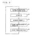
- Fig. 3 is a flowchart showing a method of controlling transmission directivity using such an estimation processing of the transmission response vector.
- the propagation path is estimated by reception response vector calculator 22 in Fig. 1. Specifically, the reception response vector of the uplink is estimated.
- moving speed determination portion 36 estimates the degree of fading, that is, the Doppler frequency FD, with the aforementioned method of determination.
- transmission response vector estimator 40 in Fig. 1 determines a plurality of frequencies ⁇ in accordance with the detected Doppler frequency FD with a method described later.
- transmission response vector estimator 40 estimates the coefficient for each signal waveform of a plurality of frequencies ⁇ determined at step S3, with a method described in conjunction with the equations (3) and (4).
- the propagation path of the downlink that is, the transmission response vector, is estimated.
- transmission weight vector calculator 30 in Fig. 1 estimates the transmission weight based on the transmission response vector of the downlink determined at step S4 described above.
- the number x of frequencies ⁇ is predetermined, in accordance with accuracy of the operation of an operation unit constituting transmission response vector estimator 40. In other words, if the number x is too large, the number of coefficients to be found will increase, the number of equations in the equation (4) will be large, and an amount of operation will be considerable. In an example described below, five types of frequencies ⁇ 1 to ⁇ 5 are assumed.
- Fig. 4 is a flowchart showing a determination processing of a frequency component ⁇ of the reception response vector in accordance with the Doppler frequency.
- step S2 corresponds to step S2 in Fig. 3, and moving speed determination portion 36 detects, in particular, the maximum value for the Doppler frequency FD.
- step S3a which is the maximum value of ⁇ is determined so as to have a prescribed relation with respect to the maximum value of FD. For example, it is assumed that ⁇ MAX is set to take a value 2 ⁇ times of FD.
- ⁇ 1 to ⁇ 5 are set so as to have prescribed relations with respect to the above described ⁇ MAX .
- ⁇ 1 is set to - ⁇ MAX
- ⁇ 2 is set to - ⁇ MAX /2
- ⁇ 3 is set to
- ⁇ 4 is set to ⁇ MAX /2
- ⁇ 5 is set to ⁇ MAX .
- ⁇ MAX 2 ⁇ FD
- the Doppler frequency FD is lower than approximately 10Hz, it is assumed that the terminal has hardly moved. If complicated calculation for estimating the transmission response vector as described above is performed by transmission response vector estimator 40 with respect to the terminal which has hardly moved, an error may be produced. With respect to the terminal which has not made a movement, it would be desirable to duplicate the reception response vector in reception as it is for use with control of transmission directivity.
- switch 38 selects the reception weight vector calculated by reception weight vector calculator 20, and provides the vector as it is to multipliers 15-1, 15-2, 15-3, 15-4 as the transmission weight vector.
- switch 38 selects the transmission weight vector newly calculated by transmission weight vector calculator 30, and provides the vector to multipliers 15-1, 15-2, 15-3, 15-4.
- measurement of the reception response vector in order to obtain the simultaneous equations in the equation (4) has been performed by setting a necessary number of timings for solving the equation within one slot of the uplink.
- the timing for measuring the reception response vector does not have to be concentrated in one transmission slot, and alternatively, may be distributed in two or more transmission slots within the uplink.
- the estimation processing incorporating extensive fluctuation on the time base of the reception response vector can be achieved, and estimation accuracy of the transmission response vector can remarkably be improved.
- the reception response vector is resolved to the signal waveform for each frequency to obtain the coefficient thereof, change of the signal waveform for each frequency is predicted by increasing time t, and the reception response vector at time t is estimated by combining the signal waveform at that time.
- the transmission response vector can be estimated, and accurate control of transmission directivity can be achieved.
- the terminal moves with a high speed, such as a case in which the Doppler frequency FD exceeds approximately 100Hz, it has been confirmed that spatial multiple access to the base station can be maintained.
- the transmission response vector in the downlink can accurately be estimated, and transmission directivity can sufficiently be implemented. This is achieved by regarding the estimated reception response vector as the composite waveform of the function of a plurality of frequencies, and by predicting and combining temporal change in the downlink for each function.
- the present invention accurate control of transmission directivity in the downlink is implemented. Therefore, the present invention is effective in a mobile communication system in which the terminal moves with a high speed, and the propagation environment fluctuates considerably.
Landscapes
- Engineering & Computer Science (AREA)
- Computer Networks & Wireless Communication (AREA)
- Signal Processing (AREA)
- Mobile Radio Communication Systems (AREA)
- Radio Transmission System (AREA)
- Variable-Direction Aerials And Aerial Arrays (AREA)
- Time-Division Multiplex Systems (AREA)
Abstract
Description
Claims (24)
- A radio base station system transmitting/receiving signals to/from a plurality of terminals using a plurality of antennas (#1-#4) arranged in a discrete manner, comprising:reception signal separation means (20) calculating a weight vector for separating a signal from a specific terminal among said plurality of terminals, based on signals received with said plurality of antennas;reception response vector estimation means (22) estimating a reception response vector of a propagation path from said specific terminal, based on signals received with said plurality of antennas;transmission response vector estimation means (40) estimating a transmission response vector of said propagation path in transmission, based on an estimation result of said reception response vector estimation means; andtransmission directivity control means (30, 38) controlling transmission directivity of said antennas, based on an estimation result of said transmission response vector estimation means; whereinsaid transmission response vector estimation means includes vector prediction means (40) regarding a function of temporal change of an element of each antenna of the reception response vector estimated by said reception response vector estimation means as a composite waveform of signal waveforms of a prescribed number of prescribed frequency components which are different from each other, predicting temporal changes at arbitrary timing positions in transmission, of the signal waveforms of respective frequency components, and synthesizing said transmission response vector.
- The radio base station system according to claim 1, wherein said vector prediction means includes
coefficient estimation means estimating coefficients of the signal waveforms of said respective frequency components, and
calculation means calculating said transmission response vector at the arbitrary timing position in transmission, based on said estimated coefficients and said prescribed frequency components. - The radio base station system according to claim 2, further comprising moving speed detecting means (36) detecting a Doppler frequency representing a moving speed of said terminal, wherein
said coefficient estimation means determines said prescribed frequency components which are different from each other, in accordance with said detected Doppler frequency. - The radio base station system according to claim 3, wherein
said coefficient estimation means determines said prescribed frequency components which are different from each other so as to have a prescribed relation with a maximum value for said detected Doppler frequency. - The radio base station system according to claim 3, wherein
said transmission directivity control means controls transmission directivity of said antenna, based on said weight vector calculated by said reception signal separation means instead of the estimation result of said transmission response vector estimation means, when said detected Doppler frequency takes a value within a range indicating that said terminal has hardly moved. - The radio base station system according to claim 2, wherein
said coefficient estimation means estimates said coefficients by solving simultaneous equations having said coefficients as unknown quantity, obtained by estimating the reception response vector at timing positions in a number at least equal to a number of said frequency components which are different from each other. - The radio base station system according to claim 6, wherein
transmission and reception of said signal is performed in a time-divided manner in a plurality of time slots respectively, and
said coefficient estimation means sets a timing position estimating said reception response vector in any one of the plurality of time slots for said reception. - The radio base station system according to claim 6, wherein
transmission and reception of said signal is performed in a time-divided manner in a plurality of time slots respectively, and
said coefficient estimation means distributes and sets timing positions estimating said reception response vector in at least two slots among the plurality of time slots for said reception. - A method of controlling transmission directivity in a radio base station system transmitting/receiving signals to/from a plurality of terminals using a plurality of antennas (#1-#4) arranged in a discrete manner, comprising the steps of:calculating a weight vector for separating a signal from a specific terminal among said plurality of terminals, based on signals received with said plurality of antennas;estimating a reception response vector of a propagation path from said specific terminal, based on signals received with said plurality of antennas;estimating a transmission response vector of said propagation path in transmission, based on said estimated reception response vector; andcontrolling transmission directivity of said antennas, based on said estimated transmission response vector; whereinsaid step of estimating said transmission response vector includes the steps ofregarding a function of temporal change of an element of each antenna of said estimated reception response vector as a composite waveform of signal waveforms of a prescribed number of prescribed frequency components which are different from each other,predicting temporal changes at arbitrary timing positions in transmission, of the signal waveforms of respective frequency components, andsynthesizing said transmission response vector.
- The method of controlling transmission directivity according to claim 9, wherein
said step of synthesizing includes the steps of
estimating coefficients of the signal waveforms of said respective frequency components, and
calculating said transmission response vector at the arbitrary timing position in transmission, based on said estimated coefficients and said prescribed frequency components. - The method of controlling transmission directivity according to claim 10, further comprising the step of detecting a Doppler frequency representing a moving speed of said terminal, wherein
said step of estimating said coefficient includes the step of determining said prescribed frequency components which are different from each other, in accordance with said detected Doppler frequency. - The method of controlling transmission directivity according to claim 11, wherein
said step of estimating said coefficient includes the step of determining said prescribed frequency components which are different from each other so as to have a prescribed relation with a maximum value for said detected Doppler frequency. - The method of controlling transmission directivity according to claim 11, wherein
said step of controlling transmission directivity of said antenna includes the step of controlling transmission directivity of said antenna, based on said calculated weight vector instead of said estimated transmission response vector, when said detected Doppler frequency takes a value within a range indicating that said terminal has hardly moved. - The method of controlling transmission directivity according to claim 10, wherein
said step of estimating said coefficient includes the step of estimating said coefficients by solving simultaneous equations having said coefficients as unknown quantity, obtained by estimating the reception response vector at timing positions in a number at least equal to a number of said frequency components which are different from each other. - The method of controlling transmission directivity according to claim 14, wherein
transmission and reception of said signal is performed in a time-divided manner in a plurality of time slots respectively, and
in said step of estimating said coefficient, a timing position estimating said reception response vector is set in any one of the plurality of time slots for said reception. - The method of controlling transmission directivity according to claim 14, wherein
transmission and reception of said signal is performed in a time-divided manner in a plurality of time slots respectively, and
in said step of estimating said coefficient, timing positions estimating said reception response vector are distributed and set in at least two slots among the plurality of time slots for said reception. - A program for controlling transmission directivity in a radio base station system transmitting/receiving signals to/from a plurality of terminals using a plurality of antennas (#1-#4) arranged in a discrete manner, causing a computer to execute the steps of:calculating a weight vector for separating a signal from a specific terminal among said plurality of terminals, based on signals received with said plurality of antennas;estimating a reception response vector of a propagation path from said specific terminal, based on signals received with said plurality of antennas;estimating a transmission response vector of said propagation path in transmission, based on said estimated reception response vector; andcontrolling transmission directivity of said antennas, based on said estimated transmission response vector; whereinsaid step of estimating said transmission response vector includes the steps ofregarding a function of temporal change of an element of each antenna of said estimated reception response vector as a composite waveform of signal waveforms of a prescribed number of prescribed frequency components which are different from each other,predicting temporal changes at arbitrary timing positions in transmission, of the signal waveforms of respective frequency components, andsynthesizing said transmission response vector.
- The program for controlling transmission directivity according to claim 17, wherein
said step of synthesizing includes the steps of
estimating coefficients of the signal waveforms of said respective frequency components, and
calculating said transmission response vector at the arbitrary timing position in transmission, based on said estimated coefficients and said prescribed frequency components. - The program for controlling transmission directivity according to claim 18, further causing the computer to execute the step of detecting a Doppler frequency representing a moving speed of said terminal, wherein
said step of estimating said coefficient includes the step of determining said prescribed frequency components which are different from each other, in accordance with said detected Doppler frequency. - The program for controlling transmission directivity according to claim 19, wherein
said step of estimating said coefficient includes the step of determining said prescribed frequency components which are different from each other so as to have a prescribed relation with a maximum value for said detected Doppler frequency. - The program for controlling transmission directivity according to claim 19, wherein
said step of controlling transmission directivity of said antenna includes the step of controlling transmission directivity of said antenna, based on said calculated weight vector instead of said estimated transmission response vector, when said detected Doppler frequency takes a value within a range indicating that said terminal has hardly moved. - The program for controlling transmission directivity according to claim 18, wherein
said step of estimating said coefficient includes the step of estimating said coefficients by solving simultaneous equations having said coefficients as unknown quantity, obtained by estimating the reception response vector at timing positions in a number at least equal to a number of said frequency components which are different from each other. - The program for controlling transmission directivity according to claim 22, wherein
transmission and reception of said signal is performed in a time-divided manner in a plurality of time slots respectively, and
in said step of estimating said coefficient, a timing position estimating said reception response vector is set in any one of the plurality of time slots for said reception. - The program for controlling transmission directivity according to claim 22, wherein
transmission and reception of said signal is performed in a time-divided manner in a plurality of time slots respectively; and
in said step of estimating said coefficient, timing positions estimating said reception response vector are distributed and set in at least two slots among the plurality of time slots for said reception.
Applications Claiming Priority (3)
| Application Number | Priority Date | Filing Date | Title |
|---|---|---|---|
| JP2001211979 | 2001-07-12 | ||
| JP2001211979A JP4587357B2 (en) | 2001-07-12 | 2001-07-12 | Radio base system and transmission directivity control method |
| PCT/JP2002/007080 WO2003007506A1 (en) | 2001-07-12 | 2002-07-11 | Radio base system, transmission directional control method, and transmission directional control program |
Publications (2)
| Publication Number | Publication Date |
|---|---|
| EP1418685A1 true EP1418685A1 (en) | 2004-05-12 |
| EP1418685A4 EP1418685A4 (en) | 2009-12-30 |
Family
ID=19047212
Family Applications (1)
| Application Number | Title | Priority Date | Filing Date |
|---|---|---|---|
| EP02745989A Withdrawn EP1418685A4 (en) | 2001-07-12 | 2002-07-11 | FIXED RADIO SYSTEM, DIRECTIONALLY CONTROLLED TRANSMISSION METHOD AND DIRECTIONALLY CONTROLLED TRANSMISSION PROGRAM |
Country Status (5)
| Country | Link |
|---|---|
| US (1) | US7565171B2 (en) |
| EP (1) | EP1418685A4 (en) |
| JP (1) | JP4587357B2 (en) |
| CN (1) | CN100525140C (en) |
| WO (1) | WO2003007506A1 (en) |
Cited By (1)
| Publication number | Priority date | Publication date | Assignee | Title |
|---|---|---|---|---|
| EP1641145A1 (en) * | 2004-09-28 | 2006-03-29 | Matsushita Electric Industrial Co., Ltd. | Improved system for radio reception |
Families Citing this family (24)
| Publication number | Priority date | Publication date | Assignee | Title |
|---|---|---|---|---|
| JP3475163B2 (en) * | 2000-09-08 | 2003-12-08 | 三洋電機株式会社 | Wireless device |
| JP4744965B2 (en) * | 2004-08-09 | 2011-08-10 | パナソニック株式会社 | Wireless communication device |
| WO2006077842A1 (en) | 2005-01-19 | 2006-07-27 | Nec Corporation | Wireless communication apparatus, and antenna directivity/radio resource assigning method |
| US8009578B2 (en) | 2005-04-11 | 2011-08-30 | Panasonic Corporation | Wireless base station device, terminal, and wireless communication method |
| JP4905874B2 (en) * | 2005-04-27 | 2012-03-28 | 京セラ株式会社 | Radio communication apparatus and control method in radio communication apparatus |
| JP4457148B2 (en) | 2005-05-23 | 2010-04-28 | 富士通株式会社 | Array antenna directivity control apparatus and directivity control method |
| KR100970519B1 (en) * | 2005-06-29 | 2010-07-16 | 교세라 가부시키가이샤 | A computer readable recording medium recording a wireless communication device, a wireless communication method, and a wireless communication program. |
| JP2007081504A (en) * | 2005-09-12 | 2007-03-29 | Hitachi Kokusai Electric Inc | Channel characteristic interpolation method and apparatus in OFDM receiver |
| EP2071746A4 (en) * | 2006-09-21 | 2013-11-20 | Kyocera Corp | RADIO COMMUNICATION DEVICE AND RADIO COMMUNICATION METHOD |
| JP4778868B2 (en) * | 2006-09-21 | 2011-09-21 | 京セラ株式会社 | Wireless communication apparatus and wireless communication method |
| JP4972370B2 (en) * | 2006-09-21 | 2012-07-11 | 京セラ株式会社 | Wireless communication apparatus and wireless communication method |
| JP4829064B2 (en) * | 2006-09-28 | 2011-11-30 | 京セラ株式会社 | Wireless communication apparatus and wireless communication method |
| JP4917956B2 (en) * | 2007-04-26 | 2012-04-18 | 京セラ株式会社 | Wireless communication apparatus and signal processing method |
| CN101809890A (en) * | 2007-09-25 | 2010-08-18 | 京瓷株式会社 | Wireless communication apparatus and wireless communication method |
| WO2009069458A1 (en) * | 2007-11-29 | 2009-06-04 | Kyocera Corporation | Wireless communication device and wireless communication method |
| WO2009069459A1 (en) * | 2007-11-29 | 2009-06-04 | Kyocera Corporation | Wireless communication device and wireless communication method |
| FR2924884B1 (en) * | 2007-12-11 | 2009-12-04 | Eads Secure Networks | REDUCTION OF INTERFERENCES IN AN ORTHOGONAL FREQUENCY-DISTRIBUTED SIGNAL |
| US20110009064A1 (en) * | 2007-12-26 | 2011-01-13 | Kyocera Corporation | Wireless communication apparatus and wireless communication method |
| US8843136B2 (en) | 2008-03-10 | 2014-09-23 | Telefonaktiebolaget Lm Ericsson (Publ) | System and method for performing timing updates in a mobile device |
| JP2011049829A (en) | 2009-08-27 | 2011-03-10 | Kyocera Corp | Radio base station, radio terminal, radio relay station, radio base station system, radio communication system, and radio communication method |
| JP2011250148A (en) * | 2010-05-27 | 2011-12-08 | Kyocera Corp | Radio base station and radio communication method |
| US9121943B2 (en) | 2011-05-23 | 2015-09-01 | Sony Corporation | Beam forming device and method |
| JP2016201743A (en) * | 2015-04-13 | 2016-12-01 | 株式会社東芝 | Receiving apparatus and receiving method |
| JP7579759B2 (en) * | 2021-06-29 | 2024-11-08 | 京セラ株式会社 | Electronic device, power transmission system, control method, and control program |
Family Cites Families (6)
| Publication number | Priority date | Publication date | Assignee | Title |
|---|---|---|---|---|
| JP3432697B2 (en) * | 1997-04-02 | 2003-08-04 | 松下電器産業株式会社 | Adaptive reception diversity apparatus and adaptive transmission diversity apparatus |
| WO2000079702A1 (en) * | 1999-06-23 | 2000-12-28 | Japan As Represented By President Of Hokkaido University | Radio device |
| EP1076425B1 (en) * | 1999-08-13 | 2018-05-30 | Intel Corporation | CDMA wireless system with closed loop mode using 90 degree phase rotation and beamformer verification |
| JP3513058B2 (en) * | 1999-09-30 | 2004-03-31 | 株式会社東芝 | Mobile terminal device |
| JP2001148650A (en) * | 1999-11-19 | 2001-05-29 | Sanyo Electric Co Ltd | Wireless base station |
| US6496778B1 (en) * | 2000-09-14 | 2002-12-17 | American Gnc Corporation | Real-time integrated vehicle positioning method and system with differential GPS |
-
2001
- 2001-07-12 JP JP2001211979A patent/JP4587357B2/en not_active Expired - Fee Related
-
2002
- 2002-07-11 US US10/483,529 patent/US7565171B2/en not_active Expired - Fee Related
- 2002-07-11 WO PCT/JP2002/007080 patent/WO2003007506A1/en not_active Ceased
- 2002-07-11 EP EP02745989A patent/EP1418685A4/en not_active Withdrawn
- 2002-07-11 CN CNB028140451A patent/CN100525140C/en not_active Expired - Fee Related
Cited By (2)
| Publication number | Priority date | Publication date | Assignee | Title |
|---|---|---|---|---|
| EP1641145A1 (en) * | 2004-09-28 | 2006-03-29 | Matsushita Electric Industrial Co., Ltd. | Improved system for radio reception |
| WO2006035193A1 (en) * | 2004-09-28 | 2006-04-06 | Matsushita Electric Industrial Co., Ltd | Improved system for radio reception |
Also Published As
| Publication number | Publication date |
|---|---|
| CN1528060A (en) | 2004-09-08 |
| US7565171B2 (en) | 2009-07-21 |
| JP2003032167A (en) | 2003-01-31 |
| JP4587357B2 (en) | 2010-11-24 |
| US20040176136A1 (en) | 2004-09-09 |
| CN100525140C (en) | 2009-08-05 |
| EP1418685A4 (en) | 2009-12-30 |
| WO2003007506A1 (en) | 2003-01-23 |
Similar Documents
| Publication | Publication Date | Title |
|---|---|---|
| US7565171B2 (en) | Radio base system, transmission directional control method, and transmission directional control program | |
| EP1189364B1 (en) | Radio device | |
| EP1575187B1 (en) | Radio equipment capable of real time change of antenna directivity and Doppler frequency estimating circuit used for the radio equipment | |
| KR20030085380A (en) | Update method for beamforming weight vector of rake receiver | |
| JP2004297276A (en) | Radio base station equipment, transmission directivity control method, and transmission directivity control program | |
| KR100870287B1 (en) | Wireless signal processing methods and apparatuses including directions of arrival estimation | |
| CN1551529B (en) | Array antenna communication device | |
| JP3548156B2 (en) | Adaptive array radio | |
| EP1489757B1 (en) | Radio reception device, array parameter optimal value estimation method, and array parameter optimal value estimation program | |
| JP5408966B2 (en) | Method for estimating the arrival time (TOA) of a received signal | |
| CN1784840B (en) | Adaptive Antenna Receiving Device with Excellent Beam Reception Quality in Initial Direction | |
| JP3423275B2 (en) | Doppler frequency estimation circuit and wireless device using Doppler frequency estimation circuit | |
| JP4441064B2 (en) | Receiving machine | |
| CN100592655C (en) | Wireless device and Doppler frequency estimation circuit for the wireless device | |
| EP1322049A1 (en) | Radio device | |
| CN118282460A (en) | Multi-antenna received signal processing method and device in GMSK frequency hopping communication system | |
| KR20060070059A (en) | Wireless communication beam forming apparatus and method | |
| Leong | Angle-of-arrival estimation: Beamformer-based smart antennas | |
| JP4601859B2 (en) | Adaptive receiver | |
| JP3138243B2 (en) | Adaptive array device | |
| JP4606647B2 (en) | Adaptive transceiver | |
| JP4384775B2 (en) | Receiving machine | |
| JP4592662B2 (en) | Radio base apparatus, transmission power control method, and transmission power control program | |
| HK1071816B (en) | Array antenna communication device | |
| JP2005244853A (en) | Adaptive array antenna system, adaptive array antenna control method, and wireless device |
Legal Events
| Date | Code | Title | Description |
|---|---|---|---|
| PUAI | Public reference made under article 153(3) epc to a published international application that has entered the european phase |
Free format text: ORIGINAL CODE: 0009012 |
|
| 17P | Request for examination filed |
Effective date: 20040211 |
|
| AK | Designated contracting states |
Kind code of ref document: A1 Designated state(s): AT BE BG CH CY CZ DE DK EE ES FI FR GB GR IE IT LI LU MC NL PT SE SK TR |
|
| AX | Request for extension of the european patent |
Extension state: AL LT LV MK RO SI |
|
| A4 | Supplementary search report drawn up and despatched |
Effective date: 20091202 |
|
| RIC1 | Information provided on ipc code assigned before grant |
Ipc: H04B 7/04 20060101ALI20091126BHEP Ipc: H04B 7/26 20060101AFI20030128BHEP |
|
| 17Q | First examination report despatched |
Effective date: 20100311 |
|
| RAP1 | Party data changed (applicant data changed or rights of an application transferred) |
Owner name: NATIONAL UNIVERSITY CORPORATION HOKKAIDO UNIVERSIT Owner name: SANYO ELECTRIC CO., LTD. |
|
| STAA | Information on the status of an ep patent application or granted ep patent |
Free format text: STATUS: THE APPLICATION IS DEEMED TO BE WITHDRAWN |
|
| 18D | Application deemed to be withdrawn |
Effective date: 20140201 |